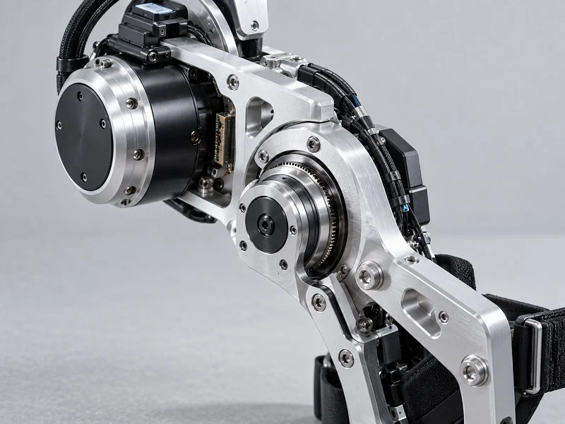
AI robot CNC machining makes important parts like harmonic drive housings, bearing seats, servo motor mounts, and sensor brackets. These parts need very tight measurements, often within ±0.005 inches or less. Reamed holes can be as accurate as ±0.0005 inches. Shops use 5-axis milling, Swiss turning, and wire EDM to create these parts. Materials include 6061 aluminum, stAInless steel, and PEEK. The biggest challenges are thin-wall distortion, keeping sub-micron tolerances, and fixturing mixed materials. To solve these, shops use smart toolpaths, stress relief steps, and adaptive control. Every robot joint, arm, and end effector relies on this exactness. That’s a quick summary. Now let’s explore the detAIls.
Overview of AI Robot CNC Machining
定義と重要性
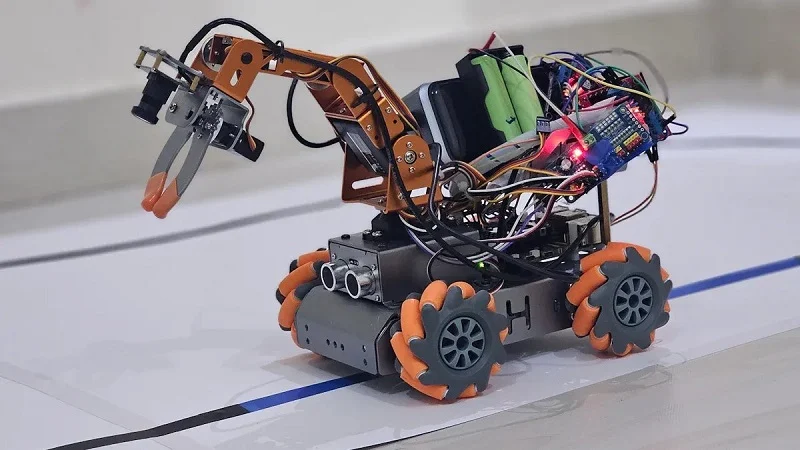
AI robot CNC machining is the craft of cutting metal and plastic into the exact shapes a robot needs to move, sense, and work. Think of it as the bridge between a robot’s design file and a real, physical machine. Without this step, a robot arm is just a drawing. The process turns raw stock into finished parts that fit together with almost no play.
Why does this matter so much? Robots repeat the same motion thousands of times a day. A tiny error in one part grows into a big error in the whole arm. That is why shops hold tolerances far tighter than what you would see in general manufacturing. The work demands care at every stage, from setup to final inspection.
主要コンポーネントの概要
Several parts show up agAIn and agAIn in robot builds. Harmonic drive housings hold the gears that give a joint its power. Bearing seats keep shafts spinning true. Servo motor mounts lock the motor in line with the joint. Sensor brackets position cameras and encoders so data stays clean. Each one plays a distinct role, yet all of them depend on tight dimensions.
These parts are not simple blocks. Many have pockets, bores, and thin walls. A housing might need a bore that stays round within a few ten-thousandths of an inch. A bracket might need a flat face so a sensor reads the same angle every time. Get one dimension wrong, and the robot’s motion drifts.
Why Precision Matters in Robotics
Accuracy in AI robot CNC machining for robotics directly shapes how well a robot moves. The numbers stay small. Machining robots typically repeat within plus or minus 0.03 mm to 0.05 mm. Machine tending robots run at plus or minus 0.05 mm to 0.1 mm. General machining precision lands in the same range, depending on the tool, spindle, and calibration.
| Robot Type / Context | 精度要件 |
| Machining robots (typical repeatability) | ±0.03mm~±0.05mm |
| Machine tending robots (precision) | ±0.05mm~±0.1mm |
| General machining precision | ±0.05mm~±0.1mm |
| Machining robots on moderate tasks | ±0.03mm~±0.1mm |
When a robot works with CNC equipment, there is very little room for error. If the robot is even slightly off when loading or unloading a part, the machine may cut in the wrong spot.
Good machining pays off in three ways:
- Better positioning accuracy: less mechanical play and better alignment between motor mounts and joint housings.
- Higher repeatability: consistent part dimensions let the robot repeat a motion with less variation.
- Reduced vibration: smooth contact surfaces cut imbalance and misalignment, which steadies motion.
CNC machining hits these targets through automated processes and advanced tools like laser interferometry, probing systems, and thermal compensation. That automation removes manual variability. Regular calibration keeps components within tolerance, and that directly lifts the repeatability of every robot movement.
Common CNC Machined Parts in AI Robot CNC Machining
Harmonic Drive Housings and Bearing Seats
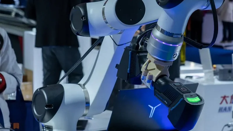
Harmonic drive housings are at the heart of every joint assembly. They keep the wave generator, flexspline, and circular spline together as one unit. These parts must line up perfectly. Even a small shift changes how the gears fit together. That lowers efficiency and makes the drive wear out faster.
Bearing seats sit inside these housings. They hold the spinning shafts steady. A seat that is not perfectly round makes the shaft wobble. The arm then loses its ability to stay in the right position. That is why machining is so important for these parts. The housing bore, the register depth, and the perpendicularity all work together as a system. When one of them is off, the whole assembly has problems.
The precision needed here is very high. The wave generator elliptical cam needs ±0.003 mm form accuracy. The flexspline thin-wall cup needs ±0.003 mm concentricity on walls only 0.3 to 0.6 mm thick. Machinists reach these numbers through careful process control and stable fixturing. Any change in form creates torque ripple. That makes the joint controller work harder to keep motion smooth.
Harmonic drives are extremely sensitive to housing geometry. The flex spline, circular spline, and wave generator come from the maker with sub-micron runout specs. If your housing bore isn’t round, if your register depth is off, if perpendicularity is loose — you will preload the flex spline unevenly and destroy a $600 component in 200 hours instead of 20,000. The mount has to be machined. There is no workaround.

Cross roller bearing seats need ±0.002 mm. The circular spline internal tooth datum bore needs ±0.003 mm. The actuator housing demands pAIred bearing seats with 0.005 mm coaxiality. Shops often use a single-setup mill-turn operation to hit that number. These figures come from the physics of gear engagement. They are not optional.
6061 aluminum is the common material for these housings. It cuts cleanly and stays stable in size. For higher loads, shops choose stAInless steel or alloy steels. The choice depends on torque demands and weight limits.
Servo Motor Mounts and Structural Frames
Servo motor mounts lock the motor in line with the joint. If the mount is off, the motor shaft binds. That wastes energy and creates heat. The arm drifts from its path over time.
Structural frames tie the whole assembly together. They connect housings, mounts, and brackets into one rigid unit. Flex in the frame causes lost accuracy at the tool tip. A frame that twists under load makes the arm position unpredictable.
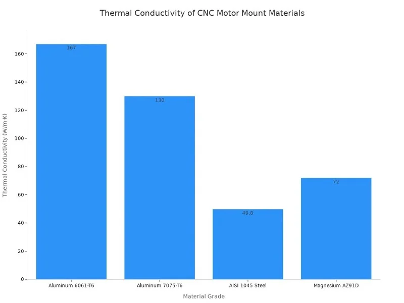
Material choice drives the performance of these parts. Here is a comparison of four common grades:
| 材料グレード | 熱伝導率(W/m・K) | 降伏強さ(MPa) | 主なメリット |
| アルミ6061-T6 | 167 | 270 | High Thermal / Lightweight |
| アルミ7075-T6 | 130 | 500-540 | Max Rigidity / Lightweight |
| AISI1045鋼 | 49.8 | 450-600 | High Stiffness / Cost-Effective |
| マグネシウム AZ91D | 72 | 160 | 超軽量 |
6061-T6 is the top pick for AI robot CNC machining of mounts in most joint assemblies. It sheds heat well and stays light. The mount doubles as a heat sink for the motor. This matters in CNC machining for robotics because heat buildup shifts alignment. Good thermal management through the mount keeps the motor running at peak torque.
7075-T6 steps up when the arm moves fast. Its higher yield strength allows thinner walls. That cuts rotational inertia and lets the arm accelerate faster. It suits high-speed axes that need stiffness without extra weight.
Steel AISI 1045 offers high stiffness at a lower material cost. Choose it where weight is less critical. Magnesium AZ91D is the lightest option. It works well for drones or portable arms that cannot afford extra mass.
Sensor Brackets and Controller Enclosures
Sensor brackets hold cameras, LiDAR units, and encoders. These parts look simple but carry tight requirements. A bracket that flexes or shifts skews the sensor reading. The robot then acts on bad data. That can ruin a pick-and-place operation or cause a collision.
Even a 1° installation angle error can cause large distance calculation errors. AI robot CNC machining solves this by hitting flatness tolerances under 0.002 mm. That keeps sensors perfectly parallel to the motion axes. A machined bracket stays in position cycle after cycle.
Controller enclosures protect the electronics. They need accurately positioned holes for connectors and cable glands. They also need sealing agAInst dust and coolant. A mismatch in hole position can prevent a connector from seating properly.
The CNC machining process for these custom robot parts delivers clear benefits:
- Tolerances as precise as ±0.005 mm ensure accurate fit for motion-critical components
- Tight alignment eliminates misalignment errors that would skew sensor readings
- Consistent structural alignment keeps data accurate under vibration and temperature changes
Materials include aluminum, stAInless steel, and sometimes Invar for temperature stability. Plastics like PEEK work well where electrical insulation matters. Each material addresses different environmental demands. Dimensional inspection reports and CMM data verify these tolerances for every part.
These sensor brackets prove that even simple-looking robotic components need tight control. Every surface and every hole matters.
Precision and Tolerances in AI Robot CNC Machining
一般的な許容範囲
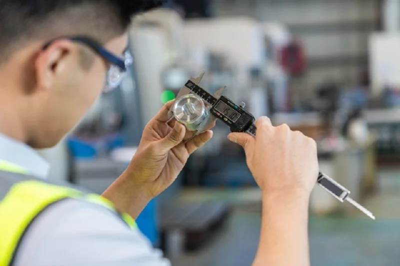
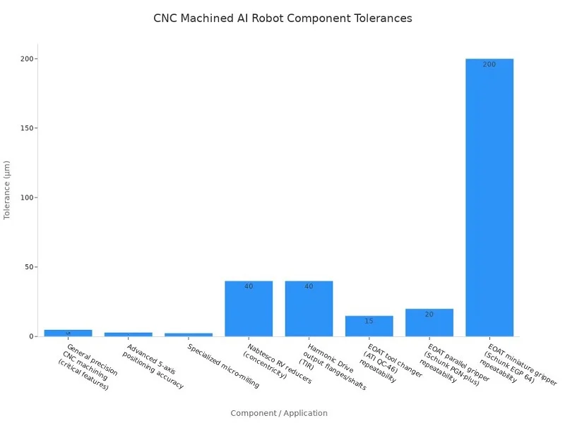
Tolerance ranges in AI robot CNC machining change based on the part and its use. General precision CNC machining keeps important features at ±0.0002 in. (±5 µm) or tighter. Advanced 5-axis machines can position parts to within 3 µm, with overall accuracy under 13 µm. Special micro-milling reaches ±0.0002 in. (2–3 µm). These numbers explAIn why robot parts need such careful machining.
Different parts have different limits. Nabtesco RV reducers need 0.03–0.05 mm concentricity, depending on size. Harmonic Drive output flanges and shafts run 0.020–0.060 mm TIR. Robotic joint gears follow ISO 1328-1 flank tolerance classes 1–11. End-of-arm tooling also varies. An ATI QC-46 tool changer repeats within 0.015 mm (0.0006 in.). A Schunk PGN-plus parallel gripper repeats within 0.02 mm. A Schunk EGP 64 miniature gripper repeats within ±0.2 mm.
| Component / Application | 一般的な許容範囲 |
| General precision CNC machining (critical features) | ±0.0002 in. (±5 µm) or tighter |
| Advanced 5-axis positioning accuracy | down to 3 µm (volumetric < 13 µm) |
| Specialized micro-milling | ±0.0002 in. (2–3 µm) |
| Nabtesco RV reducers (concentricity) | 0.03–0.05 mm (frame-size dependent) |
| Harmonic Drive output flanges/shafts (TIR) | 0.020〜0.060 mm |
| Robotic joint gears | ISO 1328-1 flank tolerance classes 1–11 |
| EOAT tool changer (ATI QC-46) repeatability | 0.015 mm(0.0006インチ) |
| EOAT parallel gripper (Schunk PGN-plus) repeatability | 20 mm |
| EOAT miniature gripper (Schunk EGP 64) repeatability | ±0.2 mm |
表面仕上げの要件
Surface finish is as important as size tolerances. For high-precision robot parts, finishes as fine as Ra 0.8 µm are possible. Special micro-milling can reach Ra 0.05 µm. That removes the need for extra polishing. These finishes are key for smooth joint movement and exact sensor placement.
A rough surface causes friction and wear. It also traps particles that mess up sensor readings. Smooth surfaces lower vibration and keep motion stable. In practice, the finish spec often decides which machining process to use. A part needing Ra 0.05 µm may need micro-milling instead of regular milling. The extra cost pays off with longer joint life and cleaner data.
測定・検査方法
Hitting tight tolerances needs more than good machining. It needs careful inspection. Shops use coordinate measuring machines (CMMs) to check sizes. Laser interferometry tests positioning accuracy across the work area. Probing systems find errors during cutting. Thermal compensation adjusts for heat expansion in real time.
These methods remove manual inconsistency. They also give data for every part. Dimensional inspection reports and CMM data confirm tolerances for sensor brackets and other key parts. Regular calibration keeps parts within spec. That directly improves repeatability of every robot movement. Without this feedback loop, even great machining precision cannot be confirmed or mAIntAIned.
Manufacturing Processes for AI Robot CNC Machining
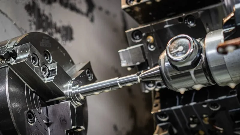
Not every process cuts parts the same way. Different shapes need different methods. Shops use three mAIn ways to build AI robot parts. Each one handles a certAIn type of part.
5‑Axis CNC Milling for Complex Geometries
5-axis CNC milling is a key method for AI robot CNC machining. A cutting tool moves along five axes at the same time. This lets it reach angled faces, undercuts, and curved surfaces without stopping to move the part.
The machining process starts from a CAD design. Engineers turn that design into cutting instructions using CAM software. Then a solid block goes into the machine. Cutting tools remove material layer by layer until the final shape appears. This keeps the metal’s mechanical properties.
3-axis machines work for simple prismatic parts. Complex robot shapes need 5-axis. Robotic assemblies often need multi-surface precision. Grippers, joints, and frames all gAIn from this approach. The advantages are clear:
- Fewer setups: One cycle reaches all sides
- Better surface finish: The tool stays at a good angle
- Tighter tolerances: Less movement means less error
- Complex shapes: Curved and angled features are no problem
- Simpler assemblies: One solid piece replaces several bolted parts
- Longer tool life: Smart angles lower heat on the tool
Common grades include 6061 and 7075 aluminum. These alloys cut cleanly and stay stable. StAInless steel works for higher loads. After milling, parts go through finishing steps. Deburring removes sharp edges. Anodizing adds a tough surface layer.
Swiss‑Type Turning for Small Shafts
Swiss-type turning handles small, slender parts. A sliding headstock pushes bar stock through a guide bushing. Cutting tools work very close to that bushing. This support stops the part from bending. The process is great for parts with high length-to-diameter ratios.
This AI robot CNC machining method suits shafts, pins, and small actuator components. Encoder shafts often come off Swiss-type machines. So do bearing pins and small connector parts. The process holds tight tolerances on very small diameters. Some pins need diameter control within 0.002 mm.
Common choices are stAInless steel, brass, and PEEK. StAInless resists corrosion. Brass cuts quickly and smoothly. PEEK offers insulation and chemical resistance. The choice depends on the robot’s operating temperature and load.
The accuracy comes from the sliding headstock design. The bar stock moves through the bushing as the tool cuts. The workpiece never moves far from the support point. So it stays rigid at high spindle speeds. This gives steady results across long runs.
For AI robot applications, Swiss turning fills a certAIn need. Harmonic drive systems need small precision pins. Sensor assemblies need exactly sized shafts for encoder disks. These parts need roundness and diameter control. Swiss-type machines deliver that without extra grinding.
Wire EDM for Hard Materials and Fine Features
Wire EDM offers a different cutting method. A thin, electrified wire passes through the workpiece. Electrical sparks erode material along a programmed path. No cutting tool touches the work. There are no cutting forces. This lets shops cut very hard stock and thin features without distortion.
The process runs on precision machine tools. The wire feeds continuously from a spool. Fluid flushes away eroded particles. The result is a burr-free edge with excellent surface finish.
Wire EDM cuts hardened steel and carbide. These materials are too hard for standard milling cutters. But they appear often in robotics. Tool steel for end-of-arm tooling gets cut with wire EDM. Carbide wear surfaces benefit too.
Wire EDM also excels at internal features. Cutting an internal gear profile with conventional milling is hard. Wire EDM does it easily through a starter hole. Narrow slots in thin walls come out clean.
The trade-off is speed. Wire EDM is slower than milling or turning. But for critical parts, the added time pays off. The accuracy and finish often remove secondary operations.
For robotics, wire EDM handles hard components and fine detAIls. It completes the AI robot CNC machining capabilities of a well-equipped shop.
Design Considerations for AI Robot CNC Machining
Lightweighting and Stiffness
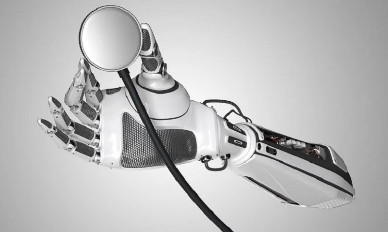
Every gram counts in a robot arm. A lighter arm moves faster and uses less energy. But cutting weight the wrong way makes the arm flex. That kills accuracy. Good design balances both goals at once.
Topology optimization helps here. Engineers remove material from zones that carry little load. The neutral axis is a common target. This drops mass without hurting strength. Five-axis machining then cuts hollow structures with internal ribs. Those ribs add torsional stiffness. High-strength 7075-T6 aluminum keeps the part rigid. Careful wall thickness changes also manage resonant frequencies. The joint interfaces get precise machining so the assembly acts like one solid piece. That stiffness holds up over millions of cycles.
It is worth noting that load paths should stay direct. Material near force transitions should stay in place. Thin sections need proper support to avoid flex under motion. Controlled stiffness beats maximum weight reduction. Every cut should keep behavior predictable. Alloys like 6061-T6 or 7075-T6 support these stiffness-to-weight goals. Precise fixturing and smart tolerance allocation prevent deformation and keep alignment.
Tolerancing for Assembly
Tolerances in AI robot CNC machining are not just a part-level concern. They are a system-level problem. Teams should think about the whole assembly from day one. Here is what matters most:
- System-level tolerancing beats part-level tolerancing, since tolerance issues are systemic, not isolated.
- Tolerance stack-up adds up across mating surfaces, so a tiny deviation on one part becomes a big positional error in the robot.
- Tolerance-sensitive features need close study, so manufacturers should work with engineering teams to map critical mating relationships.
- Assembly compatibility matters more than matching a print, because perfect parts can still cause binding joints, backlash, poor repeatability, and misalignment.
- Critical parts like aluminum joints, brackets, and structural pieces need tight tolerances, such as ±0.01 mm, plus fine surface finishes.
- DFM reviews, 5-axis single-setup machining, and CMM inspection catch errors early and improve fit.
Material Selection for Thermal and Weld-Line Performance
Heat changes size. A motor mount that grows with temperature shifts the shaft alignment. That is why thermal behavior drives material choice. Aluminum 6061-T6 sheds heat well and stays light. It often doubles as a heat sink. Alloy 7075-T6 trades some conductivity for higher strength. Steel holds stiffness but expands less predictably under load.
Weld lines matter too, especially in plastic parts. A weld line forms where two flow fronts meet. That seam is weaker than the surrounding material. It can crack under vibration. PEEK and similar plastics need careful gate placement to push weld lines away from high-stress zones. From a practical perspective, the right material and the right machining plan go hand in hand. Neither works alone.
Role of AI in AI Robot CNC Machining
How AI in CNC Machining Optimizes Toolpaths
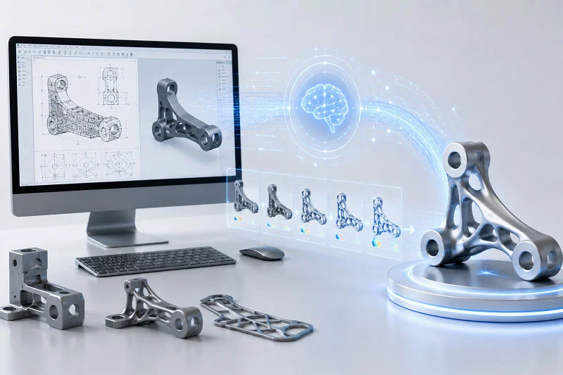
AI in CNC machining changes how cutting paths are planned. Old CAM software uses fixed rules. AI learns from past jobs instead. It looks at thousands of good cuts and spots patterns humans miss. The result is a better machining path that cuts faster and wastes less material.
This matters for robot parts with curved surfaces and deep pockets. An AI system can change machining settings as it goes. It adjusts feed rate, spindle speed, and depth of cut in real time. That improves machining efficiency without hurting the part. Good path planning also shortens the time to make each part. Shops report fewer empty moves and smoother shifts between features. The software even predicts where vibration might begin and moves the tool away before it happens.
Predictive MAIntenance and Real-Time Monitoring
Downtime ruins schedules. AI keeps machines running by checking their health. Sensors track vibration, temperature, and spindle load. The system flags problems before a tool breaks or a bearing locks up. This is predictive mAIntenance in action.
The table below shows how these methods split between CNC equipment and the robots themselves.
| Predictive MAIntenance Technique | CNC加工への応用 | Application in Robotic Systems |
| AIによる欠陥検出 | Monitors CNC mills, lathes, and 3D printers | - |
| Tool wear evaluation | Assesses tool wear to prevent tolerance drift and part imperfections | - |
| Cutting force analysis | Evaluates cutting force to mAIntAIn part accuracy | - |
| Thermal behavior monitoring | Tracks thermal behavior to avoid item imperfections | - |
| Torque tracking | - | Monitors torque in robotic arms and cobots |
| Motor health monitoring | - | Tracks motor health to detect degradation before motion accuracy or safety is affected |
| Alignment monitoring | - | Checks alignment in robotic arms and cobots to support preemptive calibration |
Real-time quality monitoring finishes the cycle. Machine vision systems check parts as they come off the spindle. If a measurement drifts, the controller fixes the next cut. Managing tool wear keeps cutters working longer without risking measurement changes. This is intelligent manufacturing at its core.
Adaptive Control for Thin‑Wall Machining
Thin walls bend from cutting force. That causes vibration, distortion, and waste. Adaptive control solves this. The system reads force readings and instantly changes feed and speed. It cuts gently when the wall is weak and cuts harder when the wall is stiff.
This works well with automatic loading and unloading. A robot arm moves parts in and out while the machine adjusts to each new raw part. An intelligent tool change system replaces worn tools without stopping the cycle. In practice, adaptive control makes a delicate job repeatable. Shops machining harmonic drive housings see fewer bad parts and tools last longer. The machine essentially learns the part as it cuts.
Challenges in AI Robot CNC Machining
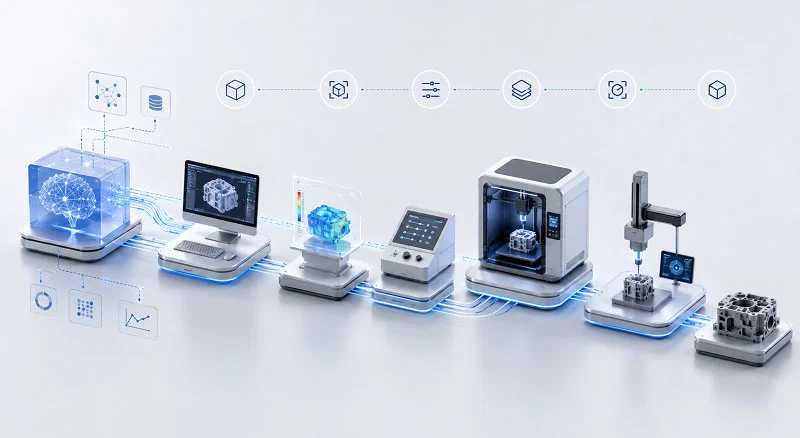
薄肉歪み
Thin walls, long spans without support, and big overhanging features all make a part less rigid while it is being cut. You should plan the machining order to reduce that effect. You can add temporary material that is removed in a final step to keep stiffness. Design bosses that hold the part steady while it is cut. Leave extra stock on thin sections until the very last operation. Rough machine from the outside in, keeping walls thicker until near-net shape is reached, then finish. Support structures and extra fixturing back up thin sections during heavy cuts to stop the worst bending problems.
Heat makes this worse. Steel grows about 12 µm per meter for each degree Celsius. A 600mm steel part that warms 5°C during cutting grows 0.036mm along its length. That matters when you hold ±0.05mm position tolerances on features at opposite ends of the part. Aluminum grows twice as fast as steel, 23 µm per meter per degree, which makes thermal control even more important for large aluminum part machining.
| Cause of Thin-Wall Distortion | 解決策 |
| Residual internal stress in raw material | Stress-relieve materials before machining |
| Excessive heat buildup during cutting | Use light, multi-pass cutting to reduce heat; allow cooling time between heavy cuts |
| Over-clamping causing elastic deformation | Avoid over-tightening vises; use soft jaws |
| Thin walls or uneven material removal | Machine symmetrically to balance material removal |
| Thin walls or flexible part geometry (chatter/vibration) | Use short, rigid tool holders and anti-vibration boring bars; optimize speeds and feeds; increase clamping contact area with custom jigs or vises; avoid deep cuts in flexible sections; use multi-pass milling |
Holding Sub‑Micron Tolerances
Sub-micron work pushes every part of the shop to its limit. Machine tools must be calibrated and kept at a stable temperature. Probing systems find errors during cutting. Thermal compensation adjusts for heat expansion in real time. Without these controls, even a great machine drifts out of spec. The feedback loop between measurement and cutting is what makes sub-micron precision repeatable.
Mixed Material Integration and Fixturing
Robots mix aluminum, steel, and plastics in one assembly. Each material cuts differently and expands at its own rate. Fixturing must hold all of them without crushing soft parts or letting hard ones slip. Custom jigs and soft jaws help. In real life, the fixture design often decides whether the job succeeds. A rigid setup with the right contact points keeps every material in place through the cut.
Case Example: AI Robot CNC Machining of Joint Housings
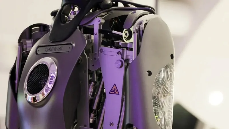
Component Description and Material Choice
Think of a joint housing for a collaborative robot arm that can lift 10 kg. This part links the servo motor to the gearbox. It also holds the bearing that lets the joint turn. It carries a steady load and must stay lined up through millions of cycles.
Material choice decides everything here. The table below shows why 7075-T6 wins for this job.
| 材料 | 降伏強さ | キーのプロパティ | ベスト |
| 6061-T6 | 〜276 MPa | Welds very well, takes hard anodizing extremely well | Most housing applications |
| 7075-T6 | 〜503 MPa | Almost twice the yield strength of 6061, weaker agAInst corrosion | Load-bearing flanges, joint yokes on high-payload arms |
7075-T6 gives 503 MPa yield strength. That is 82% more than 6061-T6. This extra strength lets engineers make walls thinner and still keep the part stiff. Thinner walls mean less inertia, so the arm speeds up faster. The downside is it resists corrosion less. Type III hard anodizing fixes that problem for factory use.
Process Selection and Sequence
The machining process begins with 5-axis roughing. This removes most of the material quickly. Then the part gets stress relief so it will not move during finishing. The steps below show the full sequence.
- Facing and Squaring — Face Mill
- Roughing Internal Cavity — High-Speed End Mill
- Semi-Finishing Bore — Boring Head
- Drilling and Tapping — Drill and Tap Set
- Finishing Flange Face — Finishing End Mill
- Machining Cable Slots — Small Diameter End Mill
- Final Bore Finishing — CBN Insert
This order is important. Rough first, then stress relief, then finish keeps the sizes steady. The final bore finishing reaches ±0.0005″ for bearing seats. One 5-axis setup handles most of the features. That lowers setup errors and saves time.
Quality Results and Lessons Learned
Inspection proves the part meets spec. The table below shows what gets checked and why.
| 測定点 | 重要な機能 | 検査理由 |
| ベアリングボア | Diameter & Roundness | Makes sure the bearing fits right and turns smoothly |
| フランジ面 | Parallelism to Bore Axis | Stops misalignment and uneven load |
| ねじ穴 | 真の位置 | Makes sure it lines up with mating parts |
| Encoder Seat | Flatness & Height | Key for accurate position feedback |
CMM inspection covers general features. Air gauges check high-precision bores below ±0.006mm. A rough surface finish above Ra 0.8μm creates stress points and lowers contact. Oval bores cause vibration. Wrong diameters damage bearings.
Design for manufacturability cut costs by about 40% from prototype to pilot run. Setup costs went down, cycle times got better, and bulk material pricing helped. Partnering with NOBLE, a leading manufacturing company in China, made this happen. Their engineering review caught problems early. Their precision CNC machining expertise turned a hard design into a repeatable product.
Partnering with NOBLE for AI Robot CNC Machining
In‑House Capabilities for Metal and Plastic
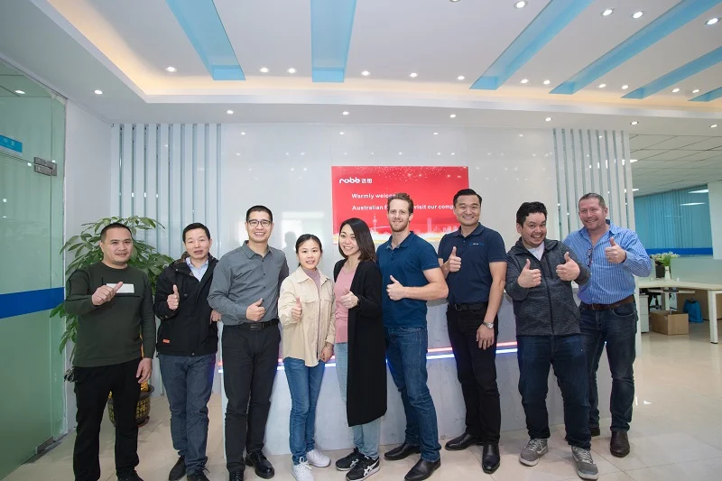
NOBLE has many years of experience cutting metal and plastic for robot makers. The workshop has both precision AI robot CNC machining and injection molding in one building. That matters. A robot arm often needs a machined aluminum joint, a molded cover, and a sheet metal frame. Getting these from three different suppliers adds wAIt time and mistakes. NOBLE keeps everything in one place.
The machines support this clAIm. Two 10-inch CNC lathes handle turning work. A vertical CNC toolroom mill and a manual Bridgeport mill cover milling jobs. A small surface grinder finishes tight spots. These machines let NOBLE hold very strict limits on plastic parts.
Materials include aluminum, stAInless steel, and engineering plastics. Typical parts go from manifolds to valve bodies. Surface finishes reach 1.6–3.2 µm Ra as-machined, and 0.8 µm Ra on a finishing pass. Turning gets 0.4–1.6 µm Ra. These numbers meet O-ring sealing groove specs of 0.8–1.6 µm Ra without extra steps.
ISO 9001:2015およびISO 13485:2016認証
Certification tells you how a shop works. NOBLE holds ISO 9001:2015 and ISO 13485:2016. The first one covers quality control for general manufacturing. The second one sets stricter rules for medical devices. That second standard demands traceability, clean process control, and documented checks at every step.
Why does this matter for robots? A robot joint that fAIls can hurt someone. The same discipline that keeps a surgical tool safe also keeps a robot arm safe. Bearing seats come off the machine at Ra 0.4–0.8 µm with 0.005 mm roundness. Swiss machining holds ±0.005 mm on small complex parts. Coating allowance on bearing bores stays at 0.05 mm. Internal sliding surfaces get MoS2 or PTFE dry film. Each number gets checked and logged.
Full‑Service from Design to Assembly
NOBLE offers a single-source service for AI robot CNC machining. The team starts with an engineering review. They point out thin walls, tight bores, and features that will fight the cutter. Then they machine the parts. After that, they assemble and kit the full set.
The integrated workflow pays off. A sheet metal frame plus CNC-machined inserts plus molded covers ship as one package. Lead times shrink. Precision holds across every piece. Robot parts like gears, shafts, and actuator housings all come from the same floor. That consistency is hard to beat when you deal with many suppliers.
AI robot CNC machining does not allow any guessing. Harmonic drive housings, bearing seats, motor mounts, and sensor brackets all need very tight precision. Shops hit those numbers using 5-axis milling, Swiss turning, and wire EDM. Materials such as 7075 aluminum and stAInless steel keep weight low and stiffness high. Design for manufacturability lowers cost and finds problems early. A skilled partner makes the difference between a prototype that works and a production run that fAIls. Ask for a DFM review or quote from a partner like NOBLE to make sure your next robot prototype or production run meets all performance and quality goals.
FAQs of AI Robot CNC Machining
What parts of an AI robot need CNC machining the most?
Harmonic drive housings, bearing seats, servo motor mounts, and sensor brackets top the list. These parts control how a joint moves and how sensors read the world. Each one needs tight dimensions. A small error in any of them throws off the whole arm.
How tight do the tolerances really need to be?
It depends on the part. Bearing bores often need ±0.0005 inches. Harmonic drive components can demand ±0.003 mm form accuracy. Sensor brackets need flatness under 0.002 mm. General precision work stays around ±0.0002 inches on critical features. These numbers come from how the parts function together.
Which materials work best for robot joints?
6061-T6 aluminum is the common choice for most housings. It cuts cleanly and sheds heat well. 7075-T6 steps up when you need more strength. It offers about 503 MPa yield strength, which lets you cut weight without losing stiffness. StAInless steel and PEEK show up too, depending on load and environment.
Why is 5-axis milling so common for these parts?
One setup reaches five sides of a part. That means fewer times you move the workpiece. Less movement equals less error. Complex shapes with angled faces and curved pockets come out cleaner. You also get better surface finish because the tool stays at a good angle.
Can AI really improve the machining process?
Yes. AI adjusts feed rates and spindle speeds in real time. It watches for vibration and tool wear before problems start. For thin-wall parts, adaptive control changes cutting force on the fly. Shops see fewer bad parts and longer tool life. The machine basically learns the part as it cuts.
What causes thin-wall distortion, and how do you stop it?
Heat and cutting force bend thin walls. Residual stress in the raw stock makes it worse. You fix this with stress relief before finishing, light multi-pass cuts, and smart fixturing. Symmetrical material removal helps too. Leave extra stock on thin sections until the last operation.
How do you check that a part meets spec?
CMMs verify sizes and positions. Air gauges check high-precision bores below ±0.006 mm. Laser interferometry tests positioning accuracy. Probing systems find errors during cutting. Thermal compensation adjusts for heat expansion in real time. Every measurement gets logged for traceability.
What should I look for in a machining partner?
Look for in-house capabilities across metal and plastic. Check for ISO 9001:2015 and ISO 13485:2016 certifications. Ask about their engineering review process. A good partner catches design problems early. They also offer assembly and kitting so you deal with one supplier instead of many.