Data centers, medical devices, and aerospace systems rely on fluidic modules CNC machining. These modular cooling parts handle heat using CNC precision machining. The process shapes complex internal CNC flow paths inside the modules. Microfluidics enables exact fluid control in these modular systems. This modular CNC method for fluidic design permits microfluidics customization. Machining these modules calls for careful material choice. CNC machining gives steady microfluidics results for modular designs. Thermal management modules depend on CNC precision machining. Cooling modules and their uses benefit from this modular CNC machining method. The fluid channels in these modules need proper microfluidics design. Microfluidics modules are a growing area for CNC machining. Fluidic module CNC machining blends several skills for modular modules. CNC machining allows modular microfluidics flow control in these modules. How do you pick the right method? This guide gives practical answers.
The Role of CNC in Fluidic Modules CNC
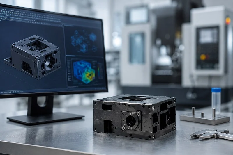
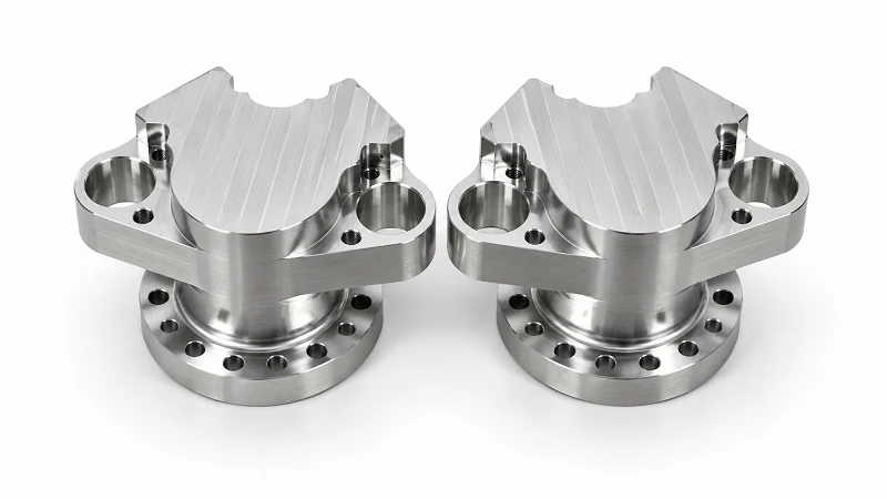
CNC machining is the main method for making fluidic modules CNC CNC. No other process gives you the same mix of accuracy, consistency, and design freedom. If you need seals that do not leak and steady performance across thousands of parts, CNC is the answer. Let’s look at why this process leads the industry.
Precision and Repeatability for Leak-Free Seals
Leaks are the biggest problem in any fluidic system. One bad seal can stop an entire cooling loop or break a medical device. CNC machining stops these failures by keeping tight control over key surfaces.
Tight Tolerances for Flatness and Surface Finish
Flatness matters more than most engineers think. When two surfaces meet with an O-ring or gasket between them, any gap can become a leak path. The flatness you need depends on your thermal interface material (TIM) thickness. Thicker TIM layers, above 0.15 mm, can fill small gaps, so a standard flatness of 0.05 mm per 300 mm often works. For TIM layers between 0.05 and 0.15 mm, you need better control—around 0.02 mm per 300 mm. Very thin interfaces below 0.05 mm need the best: flatness under 0.01 mm per 300 mm. Surface finish follows the same idea. O-ring grooves usually need roughness around Ra 0.8 µm to form a proper seal. CNC hits these finishes every time, part after part.
| TIM Thickness | Recommended Flatness | Rationale |
| > 0.15 mm | 0.05 mm | Thicker TIM can fill gaps, so extreme flatness is not needed. |
| 0.05 – 0.15 mm | 0.02 mm | Good mix of thermal performance and cost. |
| < 0.05 mm | < 0.01 mm | Needed for very low thermal resistance with thin interfaces. |
Consistency Across High-Volume Production Runs
Precision on one part is good. Precision on ten thousand parts is better. CNC machines keep tolerances across whole production runs because they follow set paths instead of relying on operator skill. This repeatability means every module in your batch works the same. For modular microfluidic systems used in diagnostics or drug delivery, that consistency is a must. A small change in channel depth could change flow rates and ruin test results.
Machining Complex Internal Geometries
Fluidic modules rarely have simple shapes. They have internal passages, branching channels, and carefully placed ports. CNC handles these complex parts with ease.
Cross-Drilled Holes and Plugging Strategies
Many fluidic designs start as solid blocks. Machinists drill channels from different angles to create internal networks. Where drill paths meet, they form flow junctions. Where they exit the part surface, machinists seal them with plugs. This cross-drilling method works well for manifolds and distribution plates. The key is placing each hole correctly so intersections line up perfectly. CNC’s accuracy makes this possible, even for deep holes with small diameters.
Creating Microchannels and Flow Paths
Microfluidics pushes CNC to its limits. Channels measured in hundreds of microns need special tooling and careful machining methods. Small end mills, sometimes under 0.5 mm in diameter, carve these fine features. The process needs rigid machine setups and little vibration. Any chatter leaves marks that disturb laminar flow. For modular microfluidic technology, these tiny channels guide fluids with great accuracy. CNC machining for liquid cooling parts also uses microchannel features to increase heat transfer surface area.
The Role of Cutting Fluids in CNC Machining
Cutting fluids do more than cool the tool. They directly affect part quality and feature integrity.
Cooling and Lubrication for Tool Life and Part Quality
Machining creates heat. Without proper cooling, that heat warps thin-walled features and speeds up tool wear. Cutting fluids carry heat away from the cutting zone, protecting both the tool and the workpiece. Lubrication lowers friction, which improves surface finish and stops material from sticking to the tool edge. For precise work on aluminum or copper, proper fluid use makes the difference between a clean cut and a torn surface.
Chip Evacuation for Clean, Burr-Free Features
Chips are a constant issue in fluidic machining. They clog small channels, scratch finished surfaces, and create burrs at hole exits. High-pressure coolant flushes chips away from the cutting zone before they cause harm. This becomes vital when machining microfluidic features. One trapped chip can ruin a channel wall or block a flow path completely. Good chip removal keeps features clean and burr-free, cutting down on extra deburring steps. For modular microfluidic platforms, clean edges matter because burrs disrupt flow patterns and trap contaminants.
CNC machining works with many materials, from aluminum and copper to engineering plastics like PEEK and acrylic. This flexibility makes it useful for many applications in thermal management, medical devices, and analytical tools. The process adapts to your material choice, not the other way around.
Manufacturing for Fluidic Modules CNC
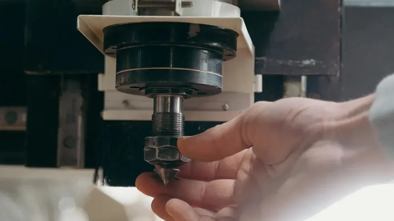
Cold plates and manifolds form the backbone of thermal management systems. Each part type demands its own design approach and manufacturing strategy. Let’s explore what makes these components work.
Cold Plates: Design and Manufacturing Considerations
Cold plates pull heat away from batteries, power electronics, and avionics. Their performance depends on channel layout and material choice. These modular components serve as the heart of many cooling architectures.
Optimizing Channel Geometry for Heat Transfer
Channel shape drives thermal performance. Serpentine paths keep coolant in contact with hot surfaces longer, boosting heat exchange. Pin-fin arrays break up the flow and create turbulence, which raises the convective heat transfer coefficient. Parallel channels lower pressure drop but risk uneven distribution across the plate. These microchannel cold plates excel in high-density thermal applications.
The trade-off is real. Narrower, deeper channels transfer more heat but push pressure drop higher. Wider, shallower paths ease the flow but sacrifice thermal performance. CFD simulation helps engineers balance these factors. For EV battery cooling, typical targets keep cell surfaces at or below 40°C during a 2C discharge, with temperature variation held within ±2°C across the module.
Manufacturing methods matter too. Controlled Atmosphere Brazing (CAB) suits complex multi-layer geometries. Friction Stir Welding (FSW) delivers higher mechanical strength and fatigue resistance, which automotive qualification often demands. CNC machining for liquid cooling components requires careful toolpath planning to maintain feature integrity.
Material Selection for Thermal Conductivity
Aluminum dominates cold plate production. Its thermal conductivity around 205 W/m·K handles most workloads at roughly one-third the weight of copper. Aerospace engineers especially value this weight savings—every kilogram affects fuel efficiency and payload capacity. These materials for CNC-machined liquid cooling components must balance performance against cost.
Copper conducts nearly twice as well at about 400 W/m·K, but the weight and cost penalties push most designers toward aluminum. Aluminum 3003 stands out for EV battery cooling. It offers adequate conductivity (155 W/m·K), excellent corrosion resistance with ethylene glycol-water coolant, and compatibility with CAB brazing and FSW.
For specialized needs, composite materials like aluminum-graphite provide directional thermal control with reduced weight, though they lack proven flight heritage. The choice of materials directly impacts thermal efficiency and system reliability.
Manifolds and Connectors for Fluid Distribution
Manifolds distribute coolant to multiple branches. Connectors join the system together. Both need careful attention to flow paths and sealing. These modules often integrate microfluidic technology for precise fluid routing.
Port-to-Port Flow Path Optimization
Every bend and junction in a manifold affects pressure drop. Engineers design port-to-port paths to minimize restriction while maintaining even distribution. Cross-drilled passages create internal networks that connect multiple ports efficiently. The goal is balanced flow to every branch, so no single channel starves or floods. Modular microfluidic technology enables compact manifold layouts that save space.
Thread Types and Sealing Methods (NPT, BSPP, SAE)
Thread selection determines leak resistance. NPT uses tapered threads that deform to seal, but the thread itself creates a leak path under high pressure. SAE ORB (O-ring Boss) seals through a compressed O-ring at the thread base, offering better reliability. BSPP needs a bonded washer or dowty seal on its straight threads. JIC 37° flare connections rely on metal-to-metal contact at the flare seat. ORFS (O-ring Face Seal) compresses an O-ring against a flat face, giving the best leak control.
For high-pressure hydraulic systems, elastomeric seals outperform threaded seals. NOBLE, a leading Chinese manufacturer, brings exceptional service and professional machining expertise to these fluidic module CNC projects. Their team helps clients move from prototyping to mass production efficiently, handling complex geometries and tight tolerances with precision. This liquid cooling component manufacturing partnership ensures quality at every stage.
Advanced Techniques and Microfluidics in Fluidic Modules CNC
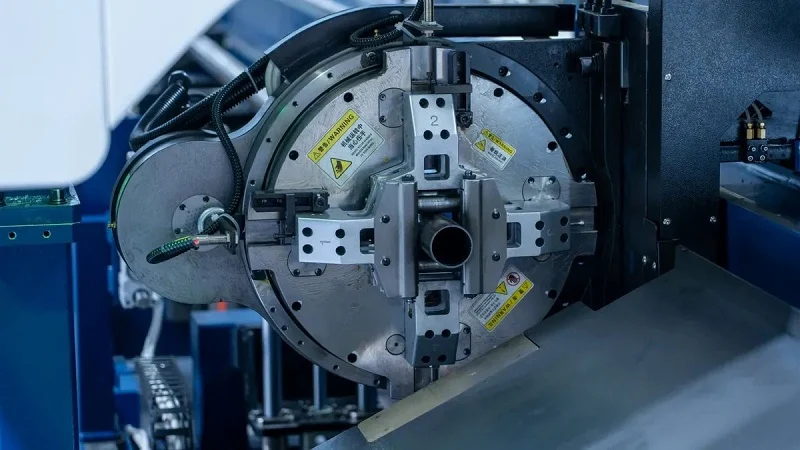
Three-axis machining handles simple blocks without issue. But fluidic modules CNC CNC often need angled ports, internal undercuts, and curved channels. That is where advanced techniques come in. Let us explore how 5-axis machining, micro-machining, and alternative processes compare for modular microfluidic systems.
5-Axis Machining for Complex Geometries
5-axis CNC machines move the tool along five axes at once. The tool can tilt and rotate while the part stays in one fixture. This changes how you approach complex fluidic modules CNC.
Reducing Setups and Improving Accuracy
Every time you remove a part from a vise and flip it, alignment risks appear. 5-axis machining eliminates most re-fixtures. A multi-port valve body gets machined on all sides in one clamping. Datum shifts disappear. True position accuracy stays consistent across every feature. Lead times shrink because parts stay in one place.
Short, rigid tools with proper tilt angles reduce vibration. Surface finishes come off the machine smooth enough to skip manual polishing. Internal flow paths stay continuous with no dynamic steps. Sealing surfaces align perfectly with pivot bores because they share the same machining setup. This guarantees concentricity for leak-proof performance.
| Advantage | Description |
| Single-setup machining | All sides machined in one clamping. No datum shifts. True position holds across all features. |
| Superior surface finish | Short rigid tools with optimal tilt prevent vibration. Sub-micron accuracy off the machine. |
| Leak-proof integrity | Internal flow paths machined without dynamic steps. Sealing surfaces and bores share the same setup. |
| Extended tool life & reduced fixture costs | Standard workholding. Shorter tools reduce chatter. Faster feed rates. |
| Design freedom | Complex freeform surfaces, internal undercuts, and compound angles become achievable. |
Machining Angled Ports and Under-Cuts
Fluidic designs often call for ports at odd angles. A manifold might need inlet and outlet ports at 30 or 45 degrees. With 3-axis machining, those angles require custom fixtures. With 5-axis, the tool simply tilts. The same goes for undercuts. Features that a straight tool cannot reach become accessible through tool tilt. This opens up new possibilities for modular microfluidic technology.
Micro-Machining for Fluidic Modules CNC Machining
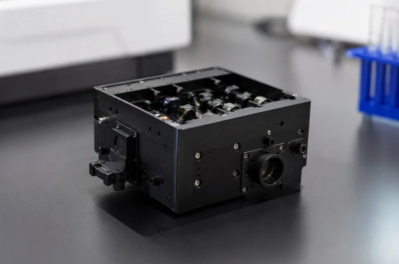
Microfluidics pushes CNC toward its physical limits. Channels measured in hundreds of microns demand special techniques. The goal is precise burr-free features that guide fluid predictably.
Achieving Fine Surface Finishes in Small Channels
Micro-milling is one of the main methods for fabricating complex microfluidic features. It creates miniature molds for micro-injection molding and precision medical components. The process uses small end mills under 0.5 mm in diameter to carve fine channels. Laser micro-machining creates microfluidic channels for diagnostic devices. Micro CNC machining enables direct fabrication of microfluidic systems needing complex geometries and controlled surface properties. It works across polymers, metals, and ceramics. These microfluidic applications benefit from the precision of modular approaches.
Tooling Considerations for Burr-Free Micro-Features
Burrs disrupt microfluidic technology. A single burr can disturb laminar flow or trap contaminants. Tool selection prevents them.
| Tooling Consideration | Relevance to Burr-Free Micro-Features |
| Tool Material | Tungsten carbide with fine grain sizes yields sharp cutting edges. |
| Cutting Edge Radius | Smaller radius (0.8–5 µm) reduces ploughing and burr formation. |
| Tapered Geometry | Reduces rubbing and improves chip evacuation. |
| Geometrical Design for Stiffness | Stiff tools resist deflection and chatter. |
Tool material matters first. Tungsten carbide with fine grain sizes keeps cutting edges sharp. The cutting edge radius, typically between 0.8 and 5 µm, influences performance most. A smaller radius reduces ploughing. Tapered geometry helps too. Stiffness rounds out the list. These tooling choices support modular microfluidic platforms and integrated microfluidic devices while maintaining precise thermal management in microchannel cold plates.
CNC vs. Alternative Manufacturing Processes
CNC machining is not always the only option. Extrusion and additive manufacturing have their own strengths. Picking the right process depends on volume, complexity, and performance needs.
Extrusion for High-Volume, Simple Cross-Sections
Extrusion works well for basic shapes. Straight channels with constant cross-sections come out quickly. Cost per part drops at high volumes. But extrusion cannot create internal branches, angled ports, or complex flow paths. Any feature needing a change in cross-section requires secondary machining. For simple cooling channels in a long straight profile, extrusion works. For anything more complex in modular microfluidic systems, CNC machining takes over.
Additive Manufacturing for Prototyping and Complex Internal Lattices
Additive manufacturing offers design freedom. You can create internal lattices and organic shapes. For prototyping, AM is fast. But AM has limitations for leak-tight fluidic modules CNC CNC. FDM resolution is constrained by nozzle diameter, typically 0.4 mm. Layer thickness affects surface roughness. Coarse features cause leakage. SLA offers better resolution but limited material options. PolyJet can produce fine features but above 200 µm with high costs.
| Manufacturing Method | Limitations for Leak-tightness | CNC Micro-milling Advantage |
| FDM (AM) | Coarse features (>300 µm). Rough surface. | Fine features (>50 µm). Smooth surface. |
| SLA (AM) | Limited material options. Medium surface. | Fine features. Wide material range. |
| PolyJet (AM) | Limited materials. High cost. >200 µm. | Fine features. Wide material range. |
| Micro-milling (CNC) | (Reference) | High accuracy (1 µm positioning). |
CNC micro-milling achieves high accuracy with positioning to 1 µm. For production modules that must hold pressure and prevent leaks, CNC remains the standard. Research continues to push these processes further. Extrusion and AM serve specific roles but cannot match the precision of machined components for modular microfluidic technology. The fluidic module cnc method combines these modular approaches into a complete workflow for leak-tight cooling modules. For cnc machining for liquid cooling components, the same principles apply—design considerations, proper tooling, and rigorous testing all come together in these modular modules.
Applications and Quality Assurance for Microfluidic Chip Fixture

Fluidic modules show up in surprising places. They cool the servers that run your cloud apps. They give insulin to diabetic patients. They control battery heat in electric cars. Each use brings its own needs, and each one depends on exact machining to work right.
Industry Applications and Their Specific Demands
Different fields push fluidic modules CNC CNC in different ways. Medical tools need safe materials and very clean parts. Car systems face constant shaking. Aerospace parts handle extreme hot and cold cycles. Knowing these needs helps you pick the right materials and making methods.
Medical Devices: Biocompatibility and Cleanliness
Medical fluidic modules CNC CNC handle drugs, chemicals, and patient samples. These microfluidics uses need materials that resist chemical damage and germ growth. The making space matters just as much as the material choice. Cleanroom assembly stops dirt that could hurt patient safety.
The table below shows typical cleanroom settings for medical fluidic module production:
| Parameter | Value |
| Cleanliness class | ISO 8 / Class 100,000 (ISO 14644-1) |
| Particle limit (≥0.5 μm) | 3,520,000 particles/m³ |
| Particle limit (≥5.0 μm) | 29,300 particles/m³ |
| Filtration | HEPA, 99.97% at 0.3 μm |
| Air pressure | Positive (outward flow) |
| Temperature | 20–24°C ±2°C |
| Relative humidity | 40–60% RH |
| Air changes | Minimum 20 per hour |
| Monitoring | Particle counter, temperature, RH logged per shift |
These settings keep dust low during assembly and testing. Modular microfluidic systems for drug delivery depend on this clean space. One dust speck could block a channel or cause a bad reaction in a patient.
Our clean room is built and run to ISO 14644-1 Class 8 standards. We log and keep environmental data (particle counts, temperature, humidity, pressure difference) each shift. We hold ISO 13485:2016 certification — the medical device quality rule that guides our clean room work.
That note comes from NOBLE, a making partner that focuses on exact fluidic module CNC production. Their cleanroom skills support medical microfluidic uses from first samples to full runs. The mix of clean assembly and exact machining makes sure every device meets strict safety rules.
Automotive and Aerospace: Vibration Resistance and Thermal Cycling
Electric vehicle battery cooling parts face constant shaking and temperature shifts. A cooling plate might see -40°C in winter storage and 80°C during fast charging. These heat cycles stress every joint and seal. CNC machining creates one-piece structures that resist this wear better than joined parts. The machining process removes weak spots where leaks could form over time.
Aerospace avionics cooling works the same way. Parts must survive launch shaking, empty space conditions, and extreme heat changes. The materials for these parts need steady properties across wide temperature ranges. Aluminum alloys and special coppers handle these needs well. Research in this area keeps finding new answers. Fresh channel shapes improve heat transfer while lowering pressure drop. Modular microfluidic technology helps engineers test these ideas quickly before making final tools.
Data center cooling is another growing use area. Server racks create huge heat loads. Liquid cooling parts remove that heat better than air systems alone. These cooling parts run all the time, so reliability is key. A leak in a data center cooling loop can wreck costly gear and cause downtime costing thousands per minute.
Dimensional Inspection and Metrology
Exact machining means nothing without checking. Every key size needs measuring. Every reading needs records. This quality loop finds issues before they reach the field. For fluidic module CNC production, checking is not optional — it is required.
CMM (Coordinate Measuring Machine) for Complex Geometry
Coordinate measuring machines use a probe to map part surfaces. The probe touches many points, and software rebuilds the shape. CMMs work great for checking true position, flatness, and angle links between features.
For fluidic modules CNC, CMM checks port spots, sealing surface flatness, and channel depths. A manifold with eight ports needs each port placed within tight limits. CMM data confirms those spots before the part ships. This testing finds machining drift early, stopping costly fixes. The modular design of modern CMMs lets them handle parts of many sizes, from small microfluidic chips to large distribution manifolds.
In-Process Inspection and SPC (Statistical Process Control)
Waiting until final check to find issues wastes time and money. In-process checks catch problems while the machine still holds the part. Workers measure key features between steps. If a size drifts, they fix it before wasting costly material.
Statistical process control takes this further. SPC tracks readings over time and flags trends before parts fall out of range. A slow tool wear pattern shows up on the control chart days before it causes rejects. This forward-looking method keeps production running smoothly. For high-volume modular microfluidic uses, SPC gives confidence that every batch meets specs. The data also helps engineers improve their machining settings for better consistency.
Leak Testing and Pressure Validation
Leak testing is the last gate before a fluidic module ships. No amount of size accuracy matters if the part leaks under pressure. Different uses call for different test methods. The test plan you pick depends on your working pressure, allowed leak rate, and safety rules.
Helium Leak Testing for Hermetic Seals
Helium leak testing finds very small leaks. The process fills the part with helium gas, then puts it in a vacuum chamber. A mass spectrometer detects any helium escaping through tiny gaps. This method finds leaks as small as 10⁻⁹ mbar·L/s.
Medical implant devices and aerospace parts often need hermetic seals. These uses cannot allow even tiny leaks. Helium testing gives the sensitivity needed to confirm seal strength. The test itself adds confidence that the modular microfluidic platform will work well in the field. For modular microfluidic systems used in diagnostics, even small leaks can hurt test accuracy.
Hydrostatic Pressure Testing for Burst and Proof Pressure
Hydrostatic testing uses liquid pressure to check structural strength. The test fills the module with water or another fluid, then presses it to a set level. Proof pressure testing checks that the part holds its rated pressure without lasting shape change. Burst pressure testing pushes until the part breaks, setting the safety edge.
For cooling parts in data centers, proof pressure testing at 1.5 times working pressure is normal. This testing confirms the part can handle pressure jumps without leaking. The burst test data helps engineers understand failure points and design safer products. Thermal cycling tests pair well with pressure testing. They copy real working conditions where temperature shifts cause pressure changes inside the part.
These check steps work together to make sure fluidic modules CNC perform as planned. From cleanroom assembly to helium leak checks, each stage adds safety against field failures. Working with a partner like NOBLE gives you access to these test tools without buying costly gear yourself. Their fluidic module CNC skills cover everything from material choice through final checks.
The uses for exact-machined fluidic modules CNC keep growing. Data center cooling, medical testing, and electric vehicle heat control all depend on these parts. Knowing the test needs helps you set the right quality level for your product. Modular microfluidic uses in particular need strict checks because they handle sensitive biological samples or exact fluid amounts.
Practical Design and Cost Considerations
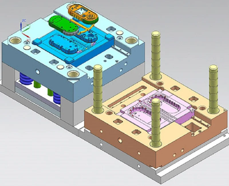
Design for manufacturability (DFM) helps projects go smoothly. It catches problems before machining starts. This review saves weeks of rework and thousands of dollars. Smart teams talk about DFM early, not after the design is done.
Design for Manufacturability (DFM) Review
Early Collaboration to Optimize Design for CNC
Include your machining partner early in design. Share your fluidic module CNC drawings while changes are still easy and cheap. A good partner finds features that will cause problems. They suggest changes that keep performance but reduce machining time. The Cytovale sepsis diagnostics platform shows this idea. Instead of a complex design, the team chose a simple, reliable method that works with manufacturing. This early alignment reduced risk. Their modular microfluidic systems moved to production without many redesigns. DFM also means setting tolerance limits that match the process. Maximum tolerances must not hurt key performance. Ignoring this leads to costly redesigns. Early collaboration sets realistic limits from the start.
Avoiding Common Pitfalls in Fluidic Design
Several traps repeat in fluidic projects. Injection molding needs draft angles for proper removal. Prototypes without these angles act differently than production parts. Include draft geometry in prototypes, so fluidic performance stays the same. Stereolithography has its own challenge. Light goes through transparent resin and cures areas it should not, causing defects. Design tools have features to fix this. A common trap is thinking you can solve integration problems later. When teams work on scalable manufacturing, they often find they designed themselves into a corner. Not meeting cost limits is the most common reason microfluidic products fail. Think about manufacturability and cost from day one.
Estimating Lead Times and Cost Drivers
Several factors drive cost in fluidic module CNC production:
- Raw material choice
- Machine cycle time
- Setup complexity (number of axes needed)
- Geometric tolerances
- Special surface finish needs
- Batch volume size
Ordering materials in bulk changes costs. Buying aluminum or copper bar stock in bulk (500+ units) cuts material costs by 10-20%.
How Material Choice and Complexity Affect Cost
Material choice affects both lead time and cost per unit. Commodity thermoplastics like ABS cut faster and cost less per kilogram. High-performance polymers like PEEK cost 10-30 times more and need slower speeds with more tool changes. Abrasive fillers wear tools faster, raising tooling costs and requiring extra finishing. For materials for CNC-machined liquid cooling components, aluminum gives the best balance. Stainless steel costs more per unit weight. Copper is high on both cost and weight. Your material choice shapes the whole budget.
| Material Category | Cost Range (per kg) | Key Impact on Lead Time & Cost |
| Commodity thermoplastics (PP, ABS) | $2–5 | Lower material cost, but more waste (20-40%) in small runs increases cost per part; faster machining reduces lead time. |
| Engineering-grade polymers | $50–150 (e.g., PEEK, LSR) | High material cost narrows the cost gap between processes; may need higher processing temperatures, extending cooling times and lead time. |
| Abrasive/glass-filled materials | Varies | Speeds up tool/mold wear, raising tooling cost per unit and needing more maintenance, which extends lead time. |
The Impact of Surface Finish and Tolerance Requirements
Tighter tolerances mean slower feeds, more inspections, and more waste. A flatness spec of 0.01 mm per 300 mm needs careful machining and CMM checks. Each extra check adds time. Surface finish requirements like Ra 0.8 µm for O-ring grooves need special tools and settings. These choices add up over a production run. Design complexity directly affects cycle time. More features mean more tool changes and longer machining. Angled ports may need 5-axis work, which costs more per hour than 3-axis. Every design decision has a cost. Research in modular microfluidic technology keeps improving these processes. New tool coatings and machine capabilities push CNC limits. But the basics stay the same: design for manufacturing, and your project stays on budget. Working with a partner who knows liquid cooling component manufacturing helps you make good choices. They advise on materials, processes, and designs to keep costs predictable. Their experience in data center cooling and medical devices gives practical tips. The modular microfluidic platform approach rewards early planning. Think about testing, assembly, and quality checks during design. This planning prevents surprises when parts reach the inspection bench.
Partnering with NOBLE for Your Fluidic Modules CNC Project

When you choose a partner for fluidic module CNC work, you need more than a machine shop. NOBLE offers the full package. From early help to final testing, everything is done in one place. That matters for complex microfluidics projects. The modular method gives steady results across every batch of modules.
Comprehensive Capabilities from Design to Assembly
NOBLE’s team works with you from the start. They give DFM feedback. This process finds problems early. For modular microfluidic systems, this review is key. They understand microfluidics well and spot issues quickly.
Engineering Support and DFM Feedback
The engineering team looks at your part shape. They suggest better ways to route channels. These modules need careful planning. For microfluidics work, every micron counts. NOBLE’s precision CNC machining experience guides your choices. Their feedback on modular layout helps you build parts that fit together easily. This modular microfluidic technology approach saves time. Their microfluidic technology knowledge covers simple channels to complex networks.
In-House Machining and Post-Processing Services
NOBLE does all CNC machining in-house. No outsourcing means quality control. They work with aluminum, copper, stainless steel, and plastics. Each material needs different speeds. After machining, post-processing steps clean every part. For thermal management parts, this keeps cooling channels clear. The flow paths stay smooth. NOBLE’s CNC machining means your modules arrive ready to assemble. The modular layout of these modules makes assembly easy.
Certifications and Quality Management
Certifications show a shop follows best practices. NOBLE has two important ones.
Adherence to ISO 9001:2015 for Quality Management
ISO 9001:2015 asks for written processes and regular checks. Every CNC part gets tracked. For modular microfluidic technology, this consistency is vital. Each module must match the last one exactly. The CNC machining process depends on this system.
Compliance with ISO 13485:2016 for Medical Device Manufacturing
Medical devices have strict rules. ISO 13485:2016 adds requirements for traceability. For microfluidics in healthcare, this certification is a must. The modular microfluidic platform NOBLE builds follows these rules. Research in microfluidics keeps pushing limits. NOBLE’s CNC machining supports this research.
A Single Source for Complex Fluidic Systems
Managing many vendors is hard. NOBLE solves this by offering everything in one place.
Integrating Machining with Assembly and Testing
NOBLE puts parts together and tests them. You get one point of contact. The team coordinates CNC machining, assembly, and testing. For modular microfluidic systems, this integration reduces fluidic connections. Fewer connections mean fewer leak points. The total fluidic envelope gets smaller, letting you build smaller instruments. This modular approach works well for complex modules. The precision of CNC machining ensures every module fits perfectly. NOBLE’s understanding of microfluidics helps create better flow paths. The fluid moves through channels with little resistance. Their microfluidic technology expertise guides each project. Thermal performance improves because channels are clean. NOBLE applies microfluidics principles to every design. NOBLE ships complete modules after final inspection.
Ensuring Supply Chain Efficiency and Project Control
When you work with one partner, you control the project better. The research phase moves faster with early team involvement. For cooling modules used in data centers, fast delivery matters. These modular microfluidic systems need careful handling. Your parts arrive fully tested and ready to install. The microfluidics community values this streamlined approach. NOBLE’s CNC machining capabilities support many applications. These modules work reliably. The modular setup allows easy integration. The coolant fluid flows through every channel. NOBLE’s microfluidics expertise guides every project.
Fluidic module CNC projects succeed when design, materials, and machining work together. CNC machining remains the gold standard for complex internal channels and leak-free seals. Material choice always involves trade-offs. Copper maximizes thermal performance but adds weight and cost. Aluminum balances conductivity with affordability. Engineering plastics resist chemicals but handle less heat.
Rigorous testing protects your investment. Helium leak testing catches microscopic gaps. Hydrostatic pressure testing confirms structural integrity. These checks prevent costly field failures.
Start planning early. Share your modular microfluidic system designs with an experienced partner before finalizing drawings. A quick DFM review saves weeks of rework. NOBLE’s team offers engineering feedback, in-house machining, and complete assembly services. Their ISO-certified processes ensure consistent quality across every production run. Consult them early to optimize your fluidic module CNC project for manufacturability and long-term reliability.
FAQ of Fluidic Modules CNC Machining
What materials suit fluidic module CNC best?
Aluminum is the top pick for most modular cooling jobs. It balances heat performance with cost. Copper moves heat better but is heavier. Stainless steel fights rust well. Engineering plastics resist chemicals. Your modular design decides the best choice. Each modular material option changes heat efficiency directly. Precision CNC machining handles all these modular choices.
How tight should modular tolerances be?
Your modular sealing surfaces need flatness near 0.02 mm per 300 mm for common thermal interface materials. O-ring grooves need a surface finish around Ra 0.8 µm. Modular microfluidic systems need even tighter control. Precision CNC machining keeps these modular tolerances steady across every modular production run. This modular precision stops leaks in cooling modules.
What testing confirms modular fluidic modules CNC won’t leak?
Helium leak testing finds tiny gaps down to 10⁻⁹ mbar·L/s. Hydrostatic pressure testing checks structural strength at 1.5 times working pressure. These modular validation steps protect your cooling system. Precision testing matters for every modular use. Your modular quality plan should include both methods for full modular confidence in your fluidic module CNC parts.
What drives modular machining costs?
Material choice tops the list. Copper costs more than aluminum. Complex modular shapes need longer cycle times. Tight modular tolerances require slower speeds and extra checks. Modular surface finishes like Ra 0.8 µm add time. Batch size matters too. Bulk modular material orders cut costs by 10-20 percent. Your modular design choices directly shape the budget.
How does modular design affect thermal performance?
Channel shape drives heat transfer. Serpentine paths keep coolant in contact longer. Pin-fin arrays create turbulence that boosts heat exchange. Narrower modular channels transfer more heat but raise pressure drop. Your modular layout must balance heat goals against flow needs. Precision CNC machining creates these modular features accurately for best thermal management.
What microfluidic applications benefit from CNC machining?
Diagnostic devices use modular microfluidic channels for sample testing. Drug delivery systems need precise modular flow control. Research labs rely on modular microfluidic platforms for experiments. CNC machining creates these modular features with accuracy other methods cannot match. Microfluidic technology keeps improving through modular design upgrades. These modular microfluidic systems handle tiny fluid volumes precisely.
How does NOBLE support modular fluidic projects?
NOBLE offers DFM feedback early in your modular design phase. Their in-house CNC machining handles complex modular shapes. ISO-certified processes ensure modular quality. They combine assembly and testing into one modular workflow. This modular approach reduces leak points and shortens lead times for cooling uses. Their modular expertise covers microfluidic technology and thermal management.
What modular design mistakes cause failures?
Skipping draft angles hurts modular injection-molded prototypes. Ignoring flatness specs creates modular leak paths. Overlooking surface finish ruins modular O-ring seals. Forgetting thermal expansion stresses modular joints. These modular errors show up during testing. Early modular DFM reviews catch them. Precision CNC machining prevents most modular design problems before production starts.