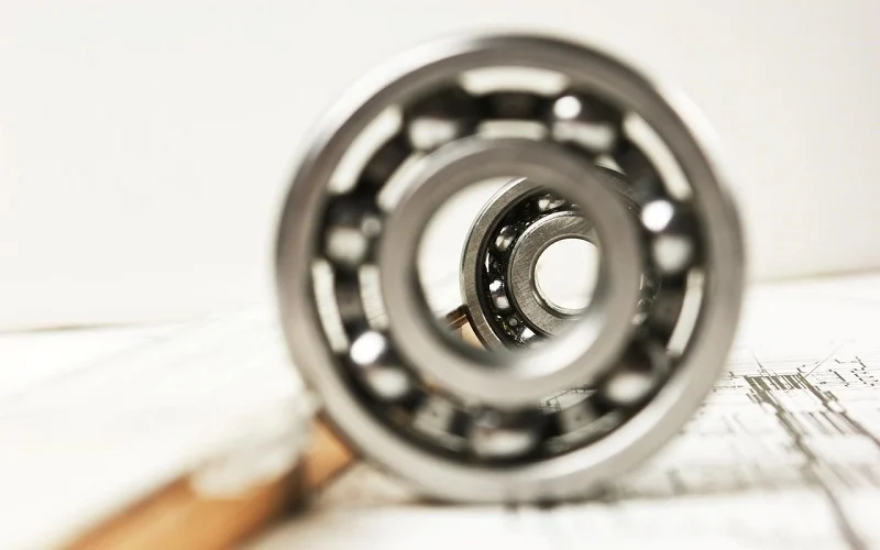
Reverse engineering captures a physical object’s geometry. A 3D scanner or CMM generates a point cloud. Software turns that into a surface model. That is the easy part.
The hard part is validating the model. Does the digital representation match the original? Will it function the same? A model on screen is not proof. That is where rapid prototyping enters.
Reverse engineering and rapid prototyping combine to form a single discipline. The existing part gets measured and modeled. The model gets printed or machined. The prototype gets compared to the original. Iteration closes the gap.
The process is essential when original drawings are missing. It is critical when parts need replacement, but no CAD exists. It is valuable when design improvements are needed, but the starting point is physical, not digital.
This guide covers the complete reverse-engineering rapid-prototyping workflow. It explains the steps, the tools, and the applications. The reader will understand when and why to use this approach.
Why Is Rapid Prototyping Needed in Reverse Engineering?
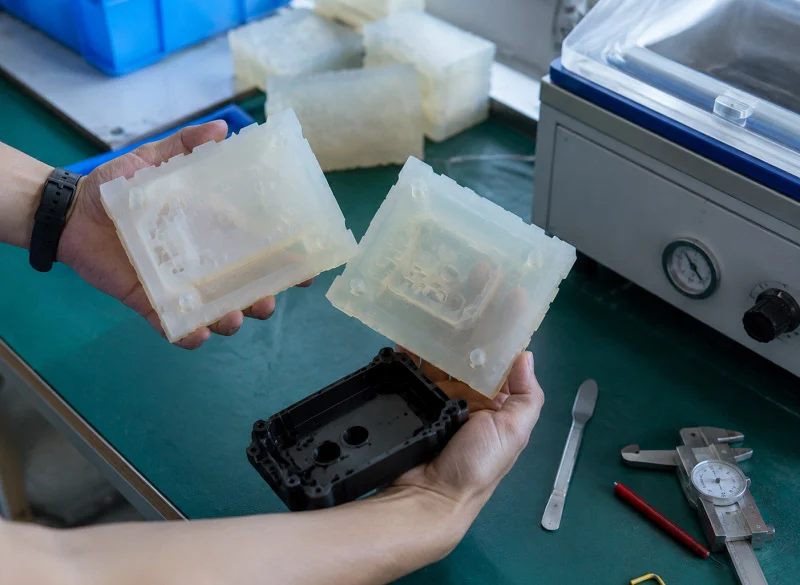
3D scanning generates a large amount of point cloud data. CAD software converts these points into surfaces. The resulting model looks similar to the original part—but that doesn’t mean it’s accurate. Errors may be introduced during the reconstruction process. The model may be close to the prototype, but for functional parts, “close” is simply not good enough.
Reverse engineering rapid prototyping validates the digital model. Will the prototype fit with existing components? Are there clearances with adjacent parts? Are fasteners aligned? A prototype can answer these questions, whereas a CAD model cannot.
Functional testing follows. Motion, loads, pressure, heat—the prototype will be subjected to real-world operating conditions. Measure performance, identify weak points, and optimize the design.
Reverse engineering rapid prototyping is not just duplication; it also drives improvement. The original part may have defects, while the reverse-engineered version may be superior.
When Is Rapid Prototyping Essential for Reverse Engineering?
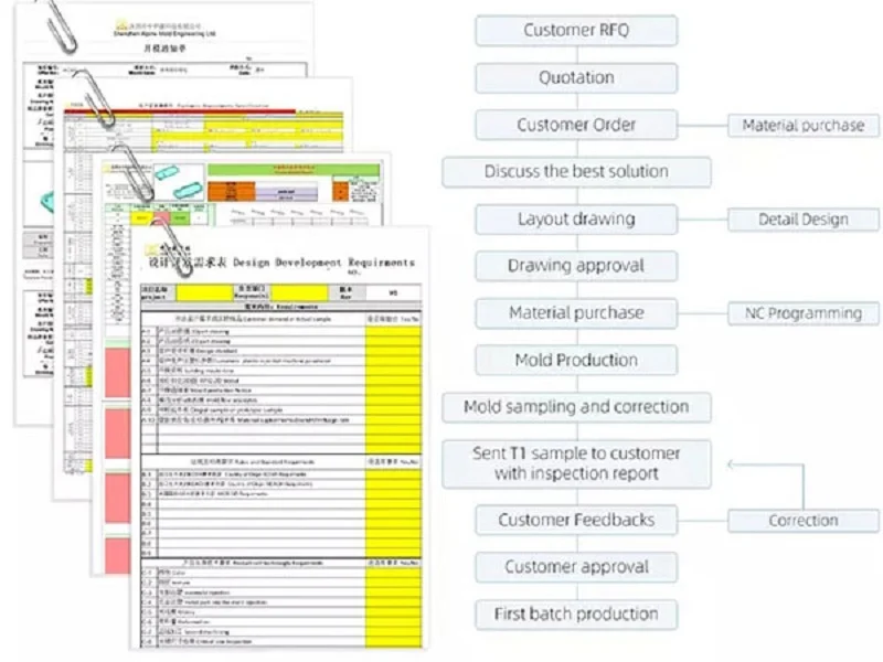
When the Original Part Is Damaged, Worn, or Unavailable
The original part is worn or even damaged, making it impossible to fully reproduce its original shape. When reconstruction requires making inferences, prototyping is used to verify those inferences.
There are no original drawings available for those missing parts—it’s possible that no relevant design drawings ever existed. Therefore, engineers must infer their design based on the parts’ installation locations and the surrounding components. A prototype tests the inference. Does it fit? Does it work? Only through prototype testing can we confirm the validity of the design.
When Dimensional Accuracy Is Critical
Tight tolerances are a hallmark of precision mechanical components. Bore positions must be precise, mating surfaces must be aligned, and joints must be sealed. Simple scanning may not accurately capture these details.
Reverse engineering rapid prototyping checks critical dimensions. By measuring the prototype, deviations from the original part can be identified and corrected before production begins.
When the Part Must Fit Existing Components
Replacement or aftermarket parts must fit perfectly. There can be absolutely no compromise on mounting points, clearances, or fastener locations. If a part does not fit properly, it is useless.
After installing the prototype onto the assembly, check the clearances, test the fasteners, and modify the CAD model. Continue making adjustments until the part finally meets the requirements.
When the Part Has Complex Geometry
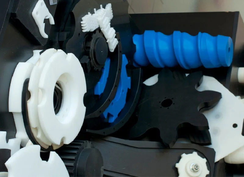
Curved surfaces, internal channels, and undercuts are hard to reconstruct. The scan may miss details. The CAD model may be simplified. The prototype exposes the gaps.
The reverse engineering rapid prototyping process validates complex geometry. The physical part is compared to the original. Deviations are visible. The model is corrected.
When Functional Testing Is Required
Visual prototypes can only demonstrate the product’s form; they cannot illustrate its performance. Functional prototypes, on the other hand, must withstand various loads and stresses, as well as the effects of temperature changes. In addition, functional prototypes need to be repeatedly assembled and disassembled.
Functional testing validates the reverse-engineered design. Does it perform like the original? Does it perform better? The prototype delivers the answers.
When the Original Design Needs Improvement
Sometimes, an existing product may have design flaws or be overly complex. Such products are likely to fail prematurely. Reverse engineering, however, can help improve the product.
Reverse engineering and rapid prototyping support innovation—they go beyond mere replication.
When Production Tooling Is Expensive
Injection molds can cost tens of thousands of yuan. Die-casting molds are even more expensive. Repair costs are also very high when a mold fails. By creating a prototype before beginning to machine the steel, various problems can be identified in advance.
Reverse engineering rapid prototyping reduces tooling risk. The design is proven before production. The mold is right the first time. Production starts on schedule. Costs are contained.
Reverse Engineering Rapid Prototyping Process: From Existing Part to Prototype
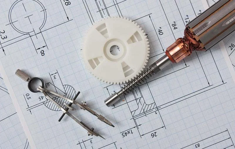
1. Inspect and Analyze the Original Part
First, engineers must carefully examine each component. They should document its geometric shape, material, connection methods between parts, wear and tear, and functional requirements. At the same time, they must identify the key features that must be faithfully reproduced exactly as they were originally.
Not all functions are equally important; some are purely aesthetic. Through analysis, engineers can distinguish between critical functions and non-critical ones. This approach saves time and effort in subsequent stages.
2. Scan and Measure the Part
Data collection has now begun. 3D laser scanning is used to capture information about an object’s surface, while structured light scanning is used to capture fine details. A coordinate measuring machine (CMM) provides high-precision point data. CT scanning helps reveal an object’s internal structure—such as various channels, cavities, and features hidden within. For areas not covered by scanning, manual measurements are required to fill in the data gaps.
Engineers typically combine multiple methods to obtain a complete dataset.
3. Process Scan Data and Create a CAD Model
Raw scan data is noisy. The point cloud data must first be cleaned and processed. At the same time, the mesh data structure needs to be simplified. Next, surface models must be reconstructed. Finally, solid geometry is built based on these surface models.
Holes, threads, curves, mounting features, and mating surfaces are recreated. The CAD model is compared to the scan data. Deviations are identified. The model is adjusted. The goal is a digital twin that matches the physical part.
Reverse engineering rapid prototyping depends on this step. A poor CAD model produces a poor prototype. The validation starts here.
4. Prepare the CAD Model for Rapid Prototyping
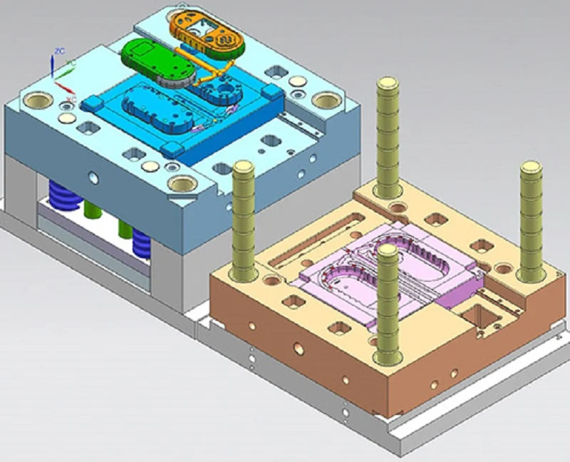
The model is not ready for production. It gets modified. Tolerances are added. Manufacturing features—draft, radii, machining allowances—are incorporated.
The model is optimized for that process. What prints well may not machine well. The preparation step bridges that gap.
5. Manufacture the Prototype
Three processes cover most needs. 3D printing is fast and handles complex geometries. CNC machining delivers high accuracy and material properties matching production. Vacuum casting produces multiple plastic or elastomer copies from one mold.
Concept prototypes can be produced through 3D printing, while functional prototypes may require machining. For small-batch production, vacuum casting can be used. In short, the manufacturing method should be tailored to specific requirements.
6. Test the Prototype
Dimension inspection begins. Engineers compare the prototype with the CAD model and record all deviations.
Next comes assembly testing. Are all components properly installed? Do the parts fit together correctly? Are the fasteners aligned?
Functional testing involves applying various loads, pressures, and heat, as well as conducting various motion tests. The prototype is then compared with the original part to identify any differences.
Reverse engineering rapid prototyping is validated at this step. The prototype proves the model. Or it exposes errors. Either way, data is collected.
7. Refine the CAD Model
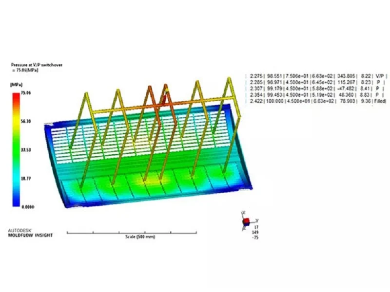
All inconsistencies have now been corrected. Dimensional problems are fixed. Functional issues are addressed. The CAD model is updated.
Additional prototypes will be created as needed. This validation process will be repeated continuously. Each iteration narrows the gap between the model and the actual product. This process will continue until all requirements are met.
8. Move the Validated Design Into Production
The model has been finalized. The drawings have been completed. The production process has been selected, and the materials have been determined.
Once the design has been validated, it moves on to the manufacturing phase. For small-batch production, vacuum casting or CNC machining can be used. For mass production, injection molding or die casting is more suitable. Prototyping is just the first step; the ultimate goal is to achieve mass production.
The reverse-engineering rapid prototyping process concludes once the manufactured product meets the design requirements. This method helps save time and reduce costs, while also ensuring the product’s accuracy and verifying its various functions.
Reverse Engineering Rapid Prototyping Services at NOBLE

Rapid Prototyping Capabilities
We manufacture both plastic and metal prototypes in-house. 3D printing technology allows us to quickly produce models with complex geometries. CNC machining, on the other hand, ensures high precision and that the material properties fully meet production requirements.
The choice of materials and processes depends on the specific application. Concept models can be printed directly, while components requiring specific functionality may need to be machined. NOBLE selects the most appropriate manufacturing process based on specific requirements.
Prototype Testing and Design Refinement
Dimension checks are used to verify that the prototype matches the CAD model. Installation and assembly tests are conducted to confirm compatibility with existing components. Any discrepancies are identified promptly.
The design is continuously optimized and refined by NOBLE engineers. Various defects are corrected. This iterative process continues until the prototype fully meets all requirements.
From Reverse Engineering to Production
NOBLE provides design and engineering support throughout the entire process. Prototyping, followed by small-batch production, assembly, and related manufacturing services, form a comprehensive service system.
Through reverse engineering and rapid prototyping, we ensure a smooth transition to mass production. Validated designs are then produced on a large scale while ensuring quality.
NOBLE holds ISO 9001:2015 certification for general quality management systems and ISO 13485:2016 certification for medical device manufacturing. These certifications ensure process consistency, traceability, and quality control.
FAQs About Reverse Engineering Rapid Prototyping
Does reverse engineering always require rapid prototyping?
Not at all. Reverse engineering can stop at the CAD model. A digital file is sometimes enough for documentation or analysis. Prototyping becomes necessary when fit, function, or performance must be validated.
Reverse engineering rapid prototyping is a choice. It is the right choice when the part will be manufactured, replaced, or modified.
What is the difference between reverse engineering and rapid prototyping?
Reverse engineering creates a digital model from a physical part. Rapid prototyping creates a physical part from a digital model. They are opposite directions. One goes from physical to digital. The other goes from digital to physical.
Combining them closes the loop. The physical part becomes a model. The model becomes a new physical part. That is reverse engineering rapid prototyping.
How accurate is reverse engineering using 3D scanning?
Accuracy depends on the scanner, the part, and the processing method. Industrial laser scanners achieve ±0.02 mm to ±0.05 mm. Structured-light scanners are similar. CT scanning captures internal geometry with comparable resolution.
Manual measurement and CMM inspection add verification. The final CAD model accuracy is a combination of scan data and reconstruction quality. Reverse engineering rapid prototyping validates that accuracy with a physical part.
Which rapid prototyping method is best for reverse engineering?
The best method depends on the application. 3D printing is fastest for complex geometries. CNC machining is best for high accuracy and production-like material properties. Vacuum casting is useful for multiple copies.
The choice is driven by material, accuracy, quantity, and function. A visual prototype can be printed. A functional prototype may need machining. Reverse engineering rapid prototyping uses the method that fits the requirement.
How long does reverse engineering and prototyping take?
Simple parts take days. Scanning and CAD reconstruction take one to two days. Printing takes hours to a day. CNC machining takes one to three days.
Complex parts take longer. Internal geometry requires CT scanning. Surface reconstruction is time-consuming. Iteration adds time. A full cycle—scan, model, prototype, test, refine—takes one to four weeks.
How much does reverse engineering rapid prototyping cost?
Cost depends on part complexity, size, accuracy requirements, and prototyping method. Simple scanned parts with basic CAD reconstruction are lower cost. Complex assemblies with multiple internal features are higher.
3D printing is cheaper than CNC machining for one-off parts. Vacuum casting is cost-effective for multiple copies. Tooling costs are avoided. The total cost is lower than production tooling errors.
Can a damaged or broken part be reverse engineered?
Yes. The process handles damaged geometry. Missing sections are reconstructed from mirror geometry, symmetry, or reference features. The prototype validates the reconstruction.
Wear patterns are analyzed. The original geometry is inferred from unworn areas. The prototype proves the inference. Reverse engineering rapid prototyping recovers parts that otherwise would be lost.
Can reverse engineering be used to improve an existing part?
Yes. The existing design is captured. Modifications are made in CAD. The new design is prototyped and tested. Performance is compared to the original.
Improvements can reduce weight, increase strength, simplify assembly, or change material. Reverse engineering is not limited to duplication. It enables design evolution.
Can a reverse-engineered prototype be used directly for production?
Sometimes. A CNC-machined prototype can serve as a production part for low volumes. A 3D-printed part typically cannot—material properties are not equivalent.
For high-volume production, the prototype validates the design. Production tooling is then manufactured. The prototype proves the design. The tooling produces the production parts. Reverse engineering rapid prototyping ensures the tooling is right the first time.