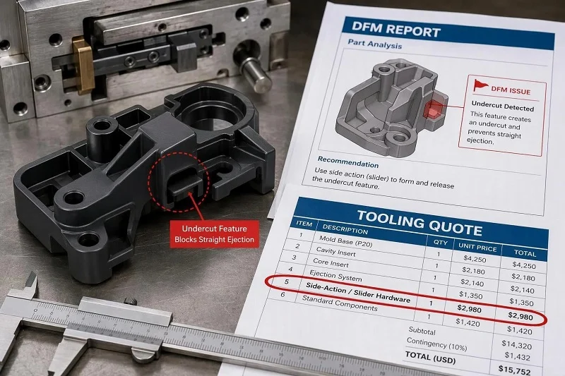
A side hole, a snap clip, a recessed groove: each looks trivial on a CAD screen and each can stop a part from leaving its mold. When a DFM report flags such a feature as an undercut and a tooling quote suddenly lists side-action hardware, the product developer meets the slider in injection molding for the first time — usually at the worst possible moment, with the tooling budget already under review.
A slider is not a workaround bolted onto a mold. It is a precision mechanism with its own geometry, load path, wear surfaces and return sequence, and understanding it early changes cost, cycle time and part quality. This guide covers what a slider is, when a part genuinely needs one, how the assembly is built and sequenced, the design principles that keep it running, the drive options, common applications, production troubleshooting, and how to plan a project around slider-bearing parts. Design engineers, tooling buyers and product developers can read any section on its own.
What Is a Slider in Injection Molding?
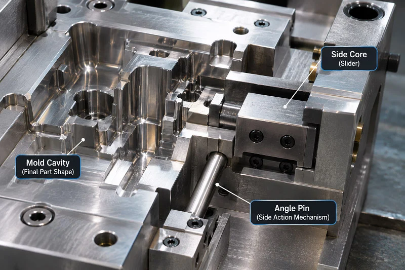
A slider in injection molding is a mold component that carries a side core or forming insert, moves perpendicular to — or at an angle to — the main opening direction, and clears an undercut before the molded part is ejected. The main mold opening supplies one draw direction; the slider adds a second, lateral release path that the opening alone cannot provide. The term as used here describes an external side action driven by an angled guide pin or a hydraulic cylinder; it is not a universal label for every undercut solution, and internal mechanisms follow different rules.
Slider vs. Lifter vs. Internal Slider: What Actually Differs
The three names describe different release paths, not three words for one device. An external slider withdraws a side feature outward as the mold opens. An internal slider moves a core toward an available internal clearance space. A lifter commonly combines movement along the ejection direction with lateral movement to release an internal undercut, so its travel is tied to the ejector stroke. Compare the actual release path, available space, ejection system, required force and maintenance access for the part in question; the names are not interchangeable.
The Undercut: The Feature That Makes a Slider Necessary
An undercut is any molded feature that blocks the part from moving along the intended release direction — a side window, a transverse hole, a clip, an external recess. If steel passes through a side window, lifting the part while that steel remains engaged can damage the feature, the tool, or both. The problem is geometric rather than resin-specific. Soft resins can sometimes be forced over shallow features, but that is a separate strategy with its own limits, not a substitute for a slider in every case.
Why and When a Part Needs a Slider in Injection Molding
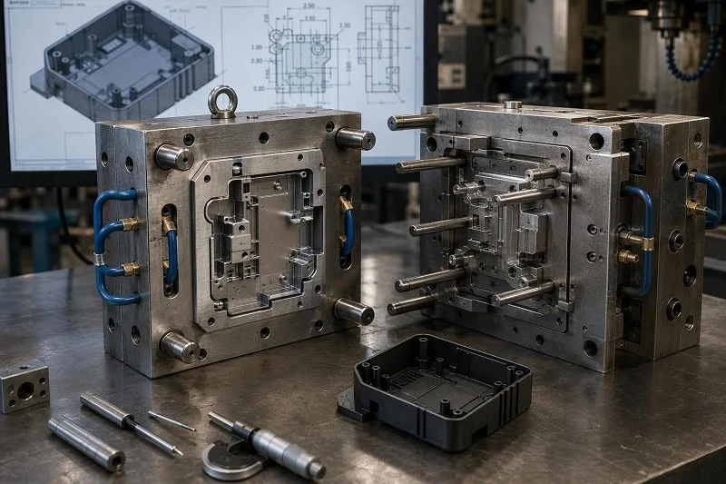
The practical question is not what a slider is but whether this feature needs one. Work through the cheaper options first; the slider is usually the third answer, not the first.
The Decision Sequence: Redesign, Shut-Off, Then Side Action
First ask whether the feature can move to the parting line, be reoriented, or change shape so it releases along the main draw. Second, test a shut-off or pass-through: a window or hole below a clip or tab lets mold steel meet through the opening and form the feature with no moving mechanism. Only if both fail is a side action justified. The order reflects cost — extra machining, extra trial rounds, added cycle seconds — though actual figures are project-specific.
When a Slider Is the Right Answer
A side action is genuinely correct for external side holes and ports, external clips and snap features that cannot convert to a shut-off, and features on outer walls unreachable from the parting line. Deep undercuts and re-entrant geometry may exceed what one slider can do and call for multi-stage or rotating mechanisms — or a design change. Sometimes the geometry, not the mechanism, is the real problem.
When a Slider Is the Wrong Answer
A slider adds cost and risk without solving the problem when an internal undercut is better served by a lifter, when a shallow feature could be forced out of a flexible resin, when a stepped or contoured parting line removes the undercut, or when the slider body competes for space with cooling and ejection. Every slider added is a wear item with a return sequence for the life of the tool.
How a Slider Assembly Is Built and How It Moves
Inside the tool, a slider is a small machine. Its parts have separate jobs, and the cycle that drives them has a fixed order. The angle pin and the locking heel do not share a function, and a design that assumes the pin resists injection pressure is a design error.
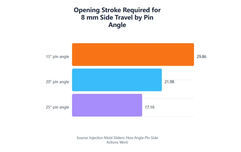
Ideal engaged opening stroke needed for the same 8 mm lateral side travel at three pin angles, calculated as opening = travel ÷ tan(angle). Values assume an ideal engaged pin and exclude lost motion, clearance, elastic deflection and friction; they illustrate the geometry only and do not recommend a pin angle.
The Components of an Angle-Pin Slider
| Component | Function | What needs checking |
| Side core or forming insert | Forms the side feature and withdraws from it | Release path, shut-off fit, steel strength, service access |
| Slider body | Carries the insert and the angled guide bore | Bore alignment, section thickness, support |
| Angled guide pin | Drives the slider while engaged | Bending load, engagement length, lead-in, fit |
| Locking heel or wedge | Supports the closed slider against side load | Contact area, seating, wear, clearance during opening |
| Gibs and wear plates | Guide the slide and support its sliding surfaces | Running fit, lubrication, hardness pairing, replaceability |
| Stop and retention device | Limits outward travel and holds the slide for return | Repeatable open position, reliable pin re-entry |
| Ejector and return system | Releases the part after clearance and resets for closing | Timing, stroke, support, collision prevention |
The heel, not the pin, carries the injection load acting on the side-forming area.
The Mold Cycle: Opening, Withdrawal, Ejection and Return
Closed and seated, the side core is in forming position, the heel supports the slider and the guide pin engages its bore. As the mold opens, relative movement drives the slider outward while the pin remains engaged, and the locking faces must separate without binding. The side core then clears the undercut with margin; if the pin exits its bore, the slide must stay guided and retained. Ejectors move only once the release path is clear, and their stroke must miss the retracted slide and the opposite half. On closing, the ejector system returns first, then the pin re-enters, the side core returns and the heel seats. The return sequence is where collisions happen.
The Travel Relationship: Opening Stroke and Pin Angle
For an ideal engaged pin, lateral travel is approximately relative opening multiplied by the tangent of the pin angle, measured from the opening axis. For the same 8 mm side travel, an ideal engaged opening works out to roughly 29.86 mm at 15°, 21.98 mm at 20° and 17.16 mm at 25° — a shallower angle needs more opening stroke, a steeper one less. The relationship stops applying after disengagement and ignores lost motion, clearance, elastic deflection and friction. No single angle is universally correct; the angle follows required withdrawal, loads, tolerances and the selected hardware.
Design Principles for a Reliable Slider in Injection Molding
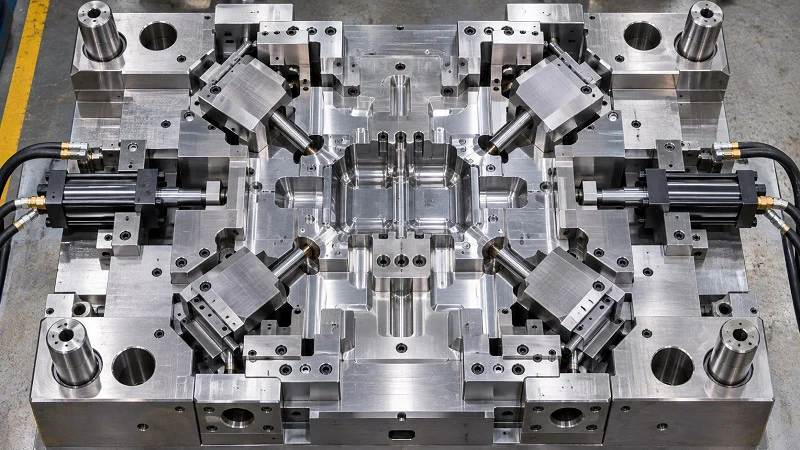
Whether a slider runs for a million shots or jams in its first week comes down to a handful of principles, each tied to a physical failure mode: insufficient stroke, binding, flash, wear, unsupported overhang and unsafe return.
Stroke, Clearance and the Release Envelope
Required travel is driven by undercut depth plus a safety margin for part release, and the complete release envelope must be proven — molded part, side core, main core, ejectors and opposite half — through opening, ejection and return. Clearance between slider and core is a trade-off: too tight binds, too loose flashes. Specific values come from the selected hardware and tolerance stack, not from a universal rule.
Draft, Shut-Offs and Surface Finish on Sliding Faces
Draft matters more on a slider than on static mold surfaces: the side core must release from the plastic without dragging. Shut-off faces need enough steel-to-steel contact at the parting line to seal against injection pressure and prevent flash, and the finish on faces that slide against plastic affects release. Draft and finish requirements scale with feature depth, resin abrasiveness and cosmetic requirements.
Guidance, Support and the Locking Arrangement
An unsupported overhang at full withdrawal creates wear and alignment problems, so sufficient bearing engagement must be kept for the real load and stroke. Injection pressure on the side-forming area produces a lateral force that the heel or wedge must carry into the mold plates; check contact area, seating and plate support. The angle pin drives motion and does not bear that pressure.
Wear Pairs, Materials and Maintenance Access
Select materials as a working pair rather than by a single hardness number: resin abrasiveness, corrosion, finish, lubrication and replaceability all influence the choice, and equal hardness throughout the assembly is not a universal requirement. Coatings and surface treatments are options whose fit depends on the application. Fasteners, inserts, gibs, wear plates and retention devices should be reachable without unnecessary mold disassembly, because a slider is a wear item by design.
Drive Methods for Sliders in Injection Molding

The drive method sets structural complexity, cycle behavior and the feasible stroke range. Treat the options as a selection problem with trade-offs rather than a ranking.
Angle-Pin Drive
The angled guide pin is the most common drive: simple, self-contained, needing no external power source, and synchronized with mold opening by geometry. Its limits are practical — pin length grows with stroke, bending strength falls as the pin lengthens, and core-pulling force is limited — so it suits small to medium strokes and moderate forces. The angle relationship between pin and locking block deserves attention to avoid self-locking or jamming during closing.
Hydraulic and Pneumatic Side Actions
An external cylinder retracts the side core independently of the opening stroke, so the sequence changes: depending on the tool, withdrawal may have to complete before the mold opens. The gains are high force, long stroke and controllable motion, which suits high-adhesion or high-hardness resins. The costs are additional power and control hardware, a more complex structure, more maintenance and greater floor-space demand. This is a different mechanism from an angle-pin slide, not a variant of it.
Bent-Pin and Other Mechanical Variants
A bent pin uses a rectangular cross-section that changes gradually along its length, resisting bending better than a round pin and tolerating larger angles. An angled-slider parting mechanism instead uses the ejection system to push the slide along an angled guide, which suits shallow side features and compact tools. Both are options for specific conditions; stroke, force, geometry and cost decide.
Applications: Where Sliders in Injection Molding Earn Their Cost
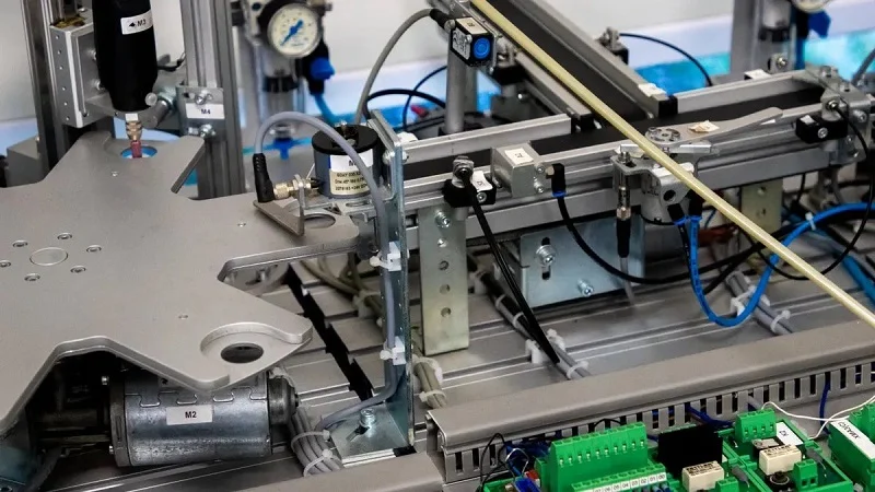
The mechanism earns its cost only where a real feature demands it. The categories below help you locate your own part; they describe common configurations, not universal requirements, and the same feature in a different resin or wall thickness may call for a different solution.
Common Part Features That Require Side Action
Side holes and ports perpendicular to the draw direction, external clips and snap arms that curve inward, side windows and openings in housings, recessed grooves around a perimeter, hooks pointing back toward the parting line, and bosses on outer walls all share one trait: the main draw cannot release them. The slider must form the feature, then withdraw far enough that the part leaves without dragging steel across it.
Industry Examples: Automotive, Medical, Consumer and Industrial
Automotive work brings interior and exterior trim, connectors, housings and under-hood components with side ports or clips. Medical devices add instrument housings, fluid-path components and enclosures where side features and cleanability matter, and where tooling qualification is rigorous. Consumer products include appliance housings, electronics enclosures with side button slots, and packaging. Industrial and robotics work covers equipment housings, sensor mounts and automation components. In every case the feature geometry and production volume drive the decision, and regulated industries layer validation requirements on top of the mechanical design.
High-Volume vs. Low-Volume Considerations
At low volume, a simpler mechanism with more manual intervention may be acceptable. At high volume, wear life, cycle-time impact and maintenance intervals dominate, because a slider adds motion to the open sequence and the cumulative machine-hour cost grows with annual shot count. Prototype and bridge tooling may use different slider constructions than a production tool; make that a deliberate decision rather than a surprise at scale-up.
Troubleshooting Sliders in Production
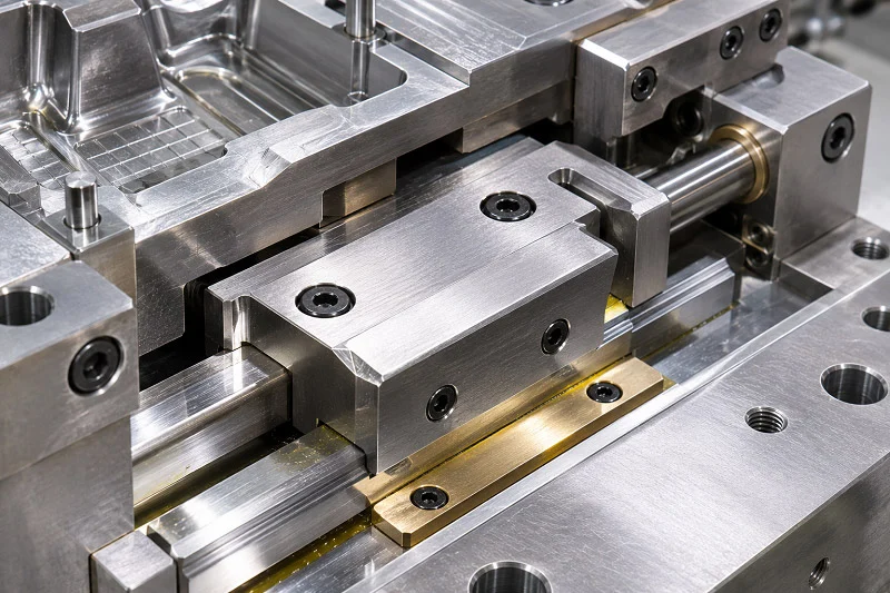
Most slider problems announce themselves as a symptom before they become a scrap bin. Read the symptom, trace it back to the design principle it violates, and confirm the diagnosis before steel is changed.
Binding, Jamming and Incomplete Reset
The slide sticks during opening, or fails to return fully before closing. Look for insufficient clearance, inadequate or degraded lubrication, mismatched angles between pin and locking block, contamination and wear debris, spring fatigue, worn limit or retention components, and interference in the reset path. Verify clearance against design intent, restore lubrication, correct angle matching, replace fatigued springs and worn retention hardware, and eliminate interference. Incomplete reset is a collision risk, not just a quality issue.
Flash, Drag Marks and Part Sticking to the Slide
Flash at the shut-off faces, drag or scuff marks on the molded feature, and a part clinging to the side core point to insufficient shut-off contact, excessive clearance, insufficient draft on slider surfaces, a rough finish on faces contacting plastic, and strong resin adhesion. Restore shut-off fit, correct clearance, increase draft where the design allows, polish contact surfaces, and review resin-specific release behavior. Some of these fixes require tooling modification, so confirm the diagnosis first.
Wear, Galling and Long-Term Maintenance Planning
Galling on sliding surfaces, wear-plate degradation, pin wear and a gradual loss of shut-off integrity are expected consequences of a wear item, and the design should make them manageable through replaceable wear plates, accessible fasteners and documented service intervals. Resin abrasiveness and operating temperature affect wear rate, which is why a schedule based on shot count is more reliable than one based on calendar time.
Designing Parts and Planning Projects Around a Slider in Injection Molding
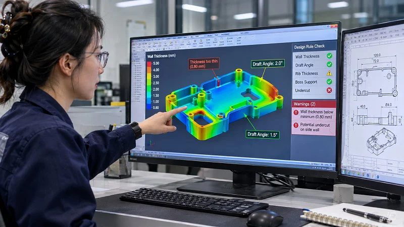
A slider in injection molding is cheapest to fix on a screen and most expensive to fix in hardened steel. The work below belongs before tooling release, and it converts the technical content of this guide into a sequence you can actually run.
The Pre-Tooling Review: What to Check Before Steel Is Cut
Prove the complete release envelope. Check guidance at full withdrawal. Size the locking arrangement against the pressure on the side-forming area. Plan safe return, including pin lead-in, repeatable retention, ejector return and monitoring. Select materials as a working pair, and allow maintenance access. On the part side, run draft analysis in the mold-opening direction, identify every flagged surface, and document a decision for each: redesign, shut-off, or mechanism. A teaching animation or CAD model illustrates movement; it does not establish loads, tolerances, service life or process approval. Validation comes from engineering review and mold trials.
Information to Provide for a Side-Action Review
Send the part CAD, resin grade, annual volume, cosmetic surfaces, critical dimensions, the specific feature that needs release, and any restrictions on parting lines, witness marks or ejector marks. Each item changes the evaluation: resin affects wear and release, volume affects mechanism choice, and cosmetic restrictions affect where the slider may leave marks. Early DFM review is where most undercut cost is avoided, because redesign and shut-off decisions are cheapest before tooling exists.
Choosing NOBLE to Support Your Injection Molding Project

NOBLE is a Sino-British joint venture and a government-recognized National High-tech Enterprise with more than 10 years of experience in parts machining and manufacturing. We provide one-stop custom manufacturing from prototyping to production, and we hold ISO 9001:2015 and ISO 13485:2016 certification. Our service capability and machining expertise are structured to help you complete prototyping and mass production efficiently, and we offer full service from design to assembly rather than production alone.
From Design Review to Prototype
For a part with side actions, the early stage is where geometry and manufacturability should be reviewed together, before tooling commitment. NOBLE’s design and prototyping support lets you verify fit and function on a physical prototype, then move into production with the same partner rather than restarting the conversation at the tooling stage.
Production, Quality and Assembly
On the production side, NOBLE combines machining and manufacturing capability with quality systems certified to ISO 9001:2015 and ISO 13485:2016, and a full-service model that runs from design through assembly. That matters for slider-bearing parts because the mechanism, the molded part and the assembly are connected; a partner covering the chain reduces handoff risk between them.
FAQs About Slider in Injection Molding
The questions below come up repeatedly in DFM reviews and tooling discussions. Each answer is scoped to what the geometry and the tool actually determine.
What is the difference between a slider and a lifter in injection molding?
A slider handles external undercuts and moves laterally, typically driven by an angled pin or a hydraulic cylinder. A lifter handles internal undercuts and moves at an angle during the ejection stroke. The choice follows the feature location and the available space, and the terms are not interchangeable.
How much side travel does a slider need?
Travel is driven by undercut depth plus a safety margin for part release. The exact figure comes from the feature geometry and from proving the release envelope, not from a universal multiplier.
Can a slider be avoided?
Often, yes. Redesign, reorientation, a shut-off or pass-through, or a parting-line strategy may release the feature without any side action. Some features genuinely need one, so document the decision during DFM.
What pin angle should an angle-pin slider use?
The angle follows required travel, available opening stroke, loads and selected hardware. Because lateral travel scales with opening times the tangent of the angle, a shallower pin needs more stroke and a steeper one less. No single angle is universally correct.
Why does a slider add cycle time?
The slide must withdraw before ejection and return before closing, so it adds motion to the open sequence. The cumulative machine-hour cost grows with annual shot count, and the magnitude depends on the mechanism type and tool design.
How do you maintain a slider over the life of a mold?
Treat it as a wear item: use replaceable wear plates and accessible fasteners, apply lubrication suited to the application, inspect pin and shut-off condition, and schedule maintenance by shot count rather than calendar time. Resin abrasiveness and operating temperature affect wear rate.
Can NOBLE support a project that involves sliders?
NOBLE provides one-stop custom manufacturing from prototyping to production, holds ISO 9001:2015 and ISO 13485:2016 certification, and offers full service from design to assembly. Projects involving side actions can be discussed on that basis.