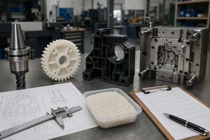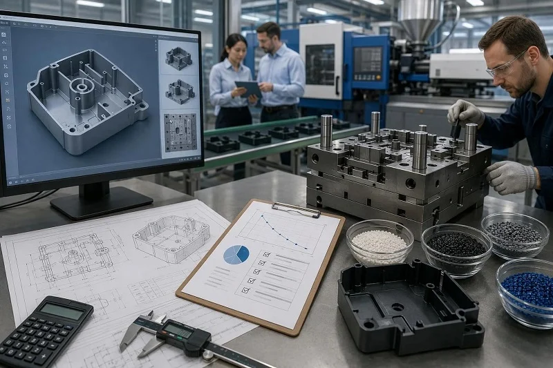
Custom injection molded parts are rarely a single purchasing decision. They are the point where a part geometry, a resin, a mold and a production volume all have to agree, and where a change made early costs far less than the same change made after steel is cut. This guide follows that sequence from the buyer’s side: what the category actually covers, how the process runs from quote request to shipped component, which design rules and materials drive moldability and cost, how molding compares with machining, printing, casting and die casting, how to choose a mold class, what quality evidence to expect, and what to prepare when sourcing overseas. Each section stands on its own, and the workflow section is the reference the later sections return to.
What Are Custom Injection Molded Parts?
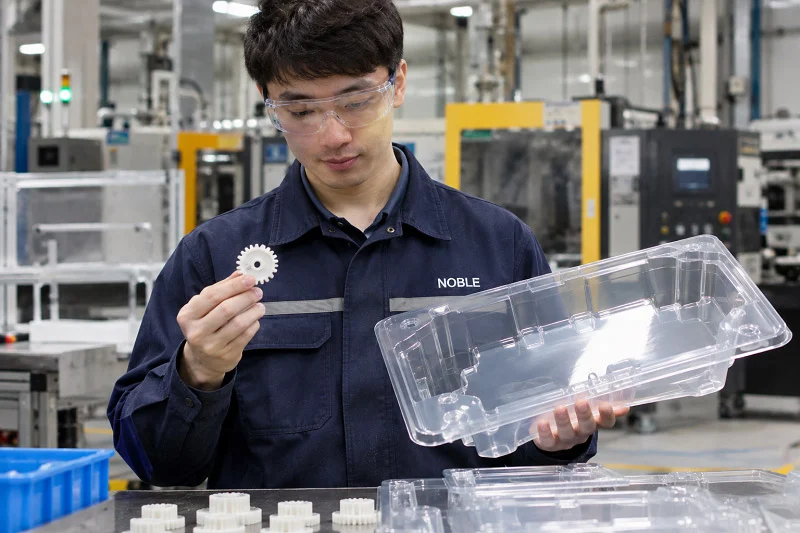
Custom injection molded parts are produced in a mold built around one specific geometry, then repeated at controlled cycle times. The “custom” refers to the tool and the part design, not the resin, which is usually a standard grade.
How Custom Tooling Differs from Standard Molded Components
Catalog components come from an existing tool with fixed geometry, little or no tooling charge and limited modification. Custom parts carry a dedicated tool and the design freedom that comes with it, with the investment recovered across volume. A modified standard part or a family tool that molds several related components together is the pragmatic middle path when volumes are modest.
The Two Stages: Building the Mold and Running the Parts
Stage one is mold construction: design review, steel selection, machining, EDM, fit-up, polishing and trial. Stage two is the production cycle itself — clamp, inject, cool, eject, repeat. Most cost and schedule risk sits in stage one; most per-part economics sit in stage two.
Why Custom Injection Molded Parts Matter in Product Development
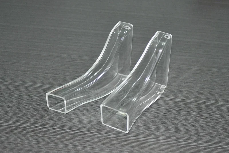
The value is net-shape geometry, repeatability, features that replace separate parts, cosmetic surfaces and a per-part cost that falls with volume. The trade-off is the upfront tooling commitment and the discipline of freezing a design before steel is cut.
Repeatability and Dimensional Consistency at Volume
A single cavity reproduces the same geometry cycle after cycle, which matters for assembly, automated handling and regulated products. Commercial tolerances commonly run around ±0.005 in (±0.127 mm) on molded features, with tighter values achievable on well-controlled dimensions in a hardened precision tool — typical ranges, not guarantees.
Integrating Features That Would Otherwise Be Separate Parts
Ribs, bosses, snap fits, living hinges, threaded inserts and overmolded grips consolidate a bill of materials. Each has a governing rule — rib thickness near half the wall, boss diameter sized to the screw, adequate draft on snap details — and ignoring those rules trades assembly savings for sink marks and ejection damage.
The Custom Injection Molding Process, Step by Step
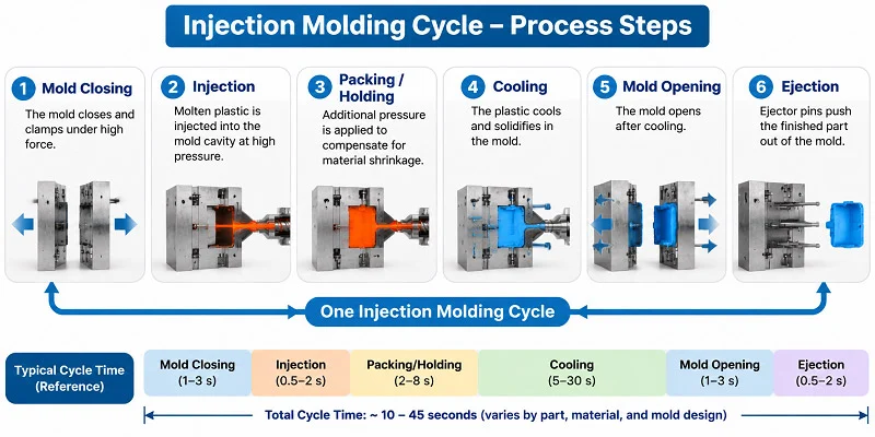
The workflow a buyer experiences runs from requirements and RFQ through DFM, design freeze, tool build, trial samples, validation and production.
From RFQ to Design for Manufacturability Review
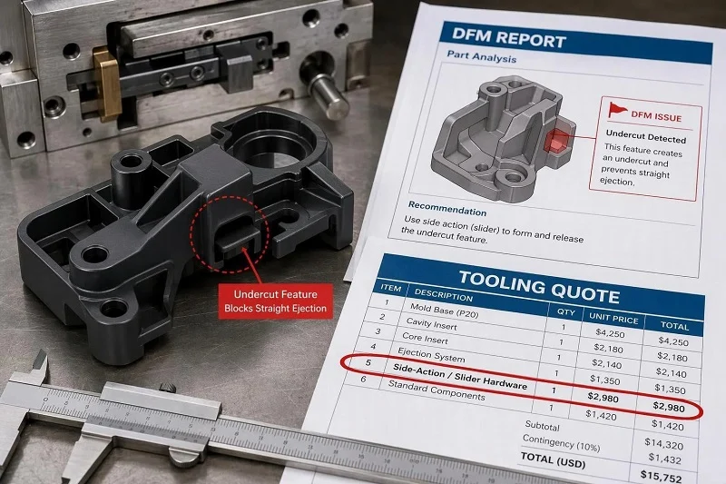
After the quote request, DFM analysis flags wall thickness, draft, undercuts, gate location, parting line and sink risk. Acting on that feedback before steel is cut is the cheapest moment to change anything.
Tool Design, Build and the First Trial Shot
Mold flow analysis on the intended cavity count and runner system settles gate placement and cooling layout. The T1 sample is the first physical evidence; relocating a gate afterwards typically adds thousands of dollars in rework per cavity and weeks of schedule.
Sample Approval, Validation and Production Release
Dimensional reports, cosmetic approval and fit-and-function testing lead to the sign-off that releases the tool. Regulated products add validation documentation on top of that baseline.
Secondary Operations and Assembly
Trimming, machining of critical features, ultrasonic welding, heat staking of inserts, pad printing, laser marking, painting and assembly are often where a molded part becomes a shippable component.
Designing Custom Injection Molded Parts for Manufacturability
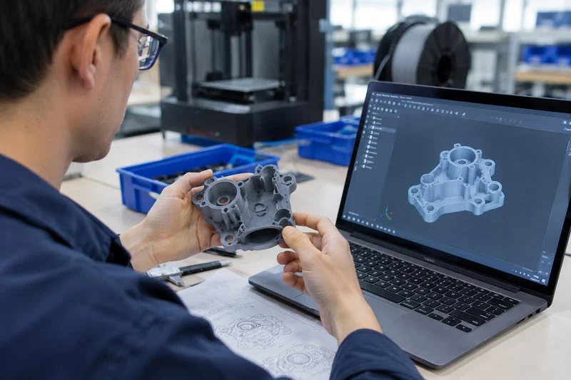
These are guidelines with reasons behind them, meant to be applied before the DFM review rather than after it.
Wall Thickness, Ribs and Bosses
Most thermoplastics mold well between roughly 1.0 and 3.5 mm, with high-flow resins filling thinner and polycarbonate wanting more. Keep secondary features at 40–60% of the adjacent wall, ribs near half the wall and bosses around twice the screw diameter.
Draft Angles, Textures and Part Ejection
Untextured walls generally need about 1.5° per side, shutoffs at least 3°, and textured surfaces 3° for light grain rising to 5–7° for heavy grain. Insufficient draft causes drag marks and ejection damage; shutoff draft is a separate requirement from general wall draft.
Undercuts, Side Actions and Parting Line Strategy
An undercut needs a side action, lifter or hand-loaded insert, and each adds tool cost and cycle time. Parting line placement decides where flash can appear and which faces stay cosmetic.
Tolerances, Shrinkage and Warp
Data-sheet shrinkage is a range measured on a standard test bar, and wall thickness, flow length, gate size and processing all shift the real result. Reserve tight tolerances for the features that need them.
Choosing the Right Material for Custom Injection Molded Parts
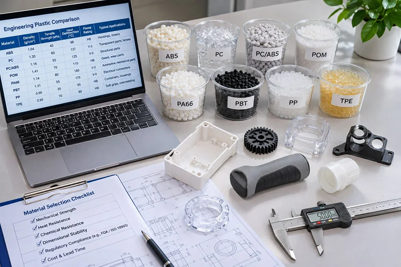
Start from the dominant service requirement — temperature, chemical exposure, mechanical load, clarity or cost — then check the secondary ones. A data sheet alone is not a selection method.
Commodity, Engineering and High-Performance Resins
Commodity resins such as PP, PE and PS cover cost-sensitive parts; engineering grades such as ABS, PC, nylon, POM and PBT cover functional parts; PEEK, PEI and PPS handle thermal and chemical extremes at markedly higher cost and tighter processing windows.
Matching Resin to Temperature and Chemical Exposure
Heat deflection temperature describes deflection under load, Vicat softening sits nearer the softening point, and the relative thermal index captures long-term aging — usually the lowest of the three. Chemical resistance must be checked against the specific agent, concentration and temperature, not a general rating.
Elastomers, Overmolding and Insert Molding
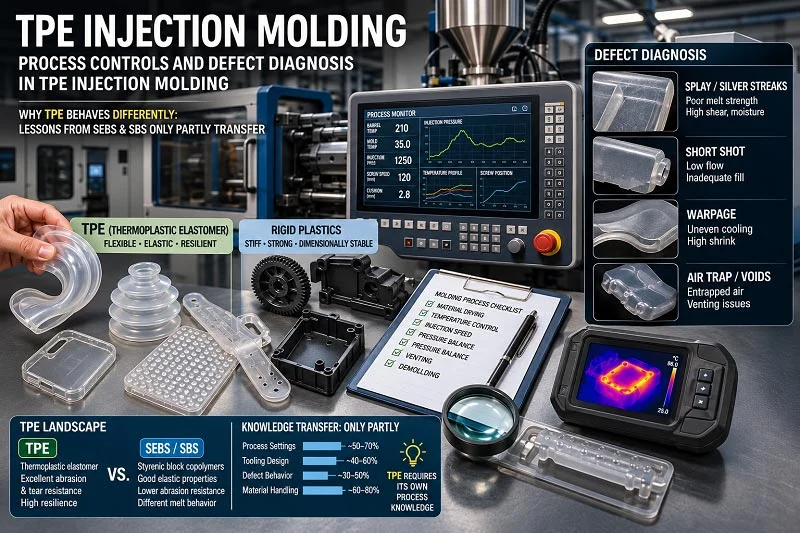
TPE, TPU and liquid silicone rubber supply flexible or sealing features; overmolding requires substrate compatibility with the second material; insert molding places threaded or electrical features in the tool before the shot.
A Practical Material Shortlist by Application
| Application need | Candidate resin families | Main trade-off |
| General housing or enclosure | ABS, ABS/PC, HIPS | Low cost and easy processing against limited UV and chemical resistance |
| Gear, cam or bearing surface | POM (acetal), PBT, glass-filled nylon | Wear resistance and stiffness against shrinkage control and moisture uptake |
| Transparent lens or light pipe | PMMA, polycarbonate | Optical clarity and scratch resistance against brittleness or UV sensitivity |
| Medical device or sterilization tray | PPSU, PEI, polycarbonate | Radiation and steam resistance against cost and thick-section molding risk |
| High-heat under-hood part | Glass-filled nylon, PPA, PPS | Temperature tolerance against warpage and tooling wear from abrasive filler |
| Chemical-handling component | PP, PPS, PEEK | Broad chemical resistance against temperature limits or very high resin cost |
Treat the table as a starting shortlist, not a selection. Confirm the specific grade, filler content and sterilization or chemical exposure before releasing steel.
Applications of Custom Injection Molded Parts Across Industries
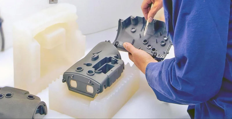
Custom injection molded parts appear in nearly every sector that ships a physical product, but each sector weights the same design and material decisions differently. The three groups below show what each industry asks of a molded part, so you can trace the requirement back to a wall thickness, a resin or a cosmetic class.
Medical Devices and Diagnostic Equipment
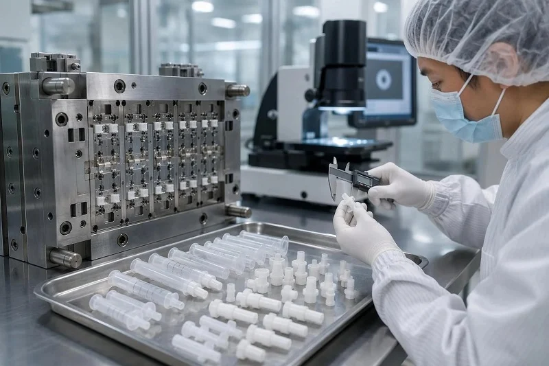
Housings, fluidic manifolds, pipette tips, sterilization trays and single-use diagnostic components are common molded parts here. The dominant requirements are resin compatibility with the chosen sterilization method, lot traceability and a quality system built for regulation. ISO 13485:2016 is the medical-device-specific quality management standard, and it emphasizes risk management and process validation beyond general quality management.
Automotive and New Energy Components
Interior and exterior trim, under-hood brackets, connectors, battery-pack frames and fluid-handling parts all rely on molding. The demands are temperature exposure, resistance to fuels, oils and coolants, and dimensional stability across a wide service range. Glass-filled engineering resins are common, which raises tooling wear and makes gate and cooling design more consequential.
Consumer Products, Electronics and Industrial Equipment
Enclosures, handheld device shells, gears, pump impellers, robotics covers and automation fixtures make up this group. Cosmetic class often dominates the specification, followed by wear resistance for moving parts and feature integration that reduces assembly steps. Color, texture and parting-line placement matter as much as the dimensional report on visible surfaces.
Custom Injection Molded Parts Compared with Other Manufacturing Processes
No process wins on every axis. The table below sets out typical industry ranges for the main options, and the subsections that follow explain the boundaries that matter most.
| Process | Best volume range | Typical tooling cost | Lead time to first part | Typical tolerance |
| CNC machining | 1–5,000+ | None | 1–5 days | ±0.025 mm |
| Injection molding | 1,000–millions | $5,000–$100,000+ | 2–12 weeks | ±0.05–0.2 mm |
| 3D printing | 1–500 | None | 1–3 days | ±0.1–0.3 mm |
| Urethane casting | 1–300 | $500–$2,000 | 1–2 weeks | ±0.2–0.4 mm |
| Die casting | 10,000+ | $10,000–$80,000+ | 6–12 weeks | ±0.1–0.25 mm |
| Sheet metal | 50–millions | $500–$20,000+ | 1–5 days | ±0.1–0.25 mm |
These are typical industry ranges, not guarantees; actual values vary with part complexity, material, supplier and program requirements.
Injection Molding vs. CNC Machining
Machining carries no tooling charge and handles certified metals and tight tolerances, so it wins at low volume and for parts needing a specific mill-certified alloy. Molding wins on per-part cost and repeatability once volume justifies the tool. The two are often sequential: machined or printed parts validate the design, then the mold reproduces it.
Injection Molding vs. 3D Printing
Printing offers geometric freedom and first parts in days, but layer-based surfaces and a narrower production material set limit it for end-use volumes. Molded parts deliver production-grade resin properties, molded surface finish and unit costs that fall sharply with volume. Printed prototypes are frequently used to check fit before tooling is committed.
Injection Molding vs. Urethane Casting and Die Casting
Urethane casting suits low-volume cosmetic and production-representative parts, typically a few hundred units from silicone molds, before molding tooling is justified. Die casting serves high-volume metal parts and needs tooling investment that generally only pays back above roughly 10,000 units. Plastic molding sits between them for polymer parts at volume.
A Process Selection Checklist
- Annual and monthly volume, and whether demand is validated or still speculative
- Tooling budget available before revenue starts
- Deadline for the first production-representative part
- Tolerance and material certification requirements
- Cosmetic class and surface finish expectations
- Likely design changes after launch
If volume is under about 1,000 parts or the design is still moving, screen machining, printing or casting first.
Tooling Strategies: Prototype, Bridge and Production Molds
The mold is a strategic purchase, not a single item on a quote. The right class depends on how mature the design is and how much demand has actually been validated, and choosing too high a class too early ties up capital before the geometry is settled.
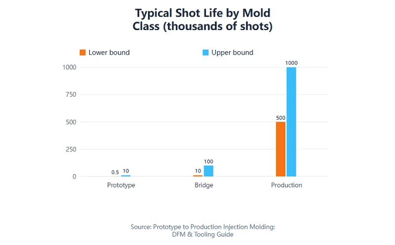
Typical industry ranges for the three tooling tiers. Shot life and lead time depend on part complexity, resin abrasiveness, cavity count and maintenance; values are reported ranges, not guarantees.
Prototype Tooling for Design Validation
Prototype tools are usually machined from aluminum alloy in a single cavity, with typical lead times of one to three weeks and shot life of roughly 500 to 10,000 shots. They exist to prove form, fit and function and to support iteration. Aluminum conducts heat far faster than steel, so prototype cycle times do not predict production cycle times.
Bridge Tooling for Launch and Early Demand
A bridge tool is an interim mold that produces saleable parts while the production tool is still being built. It is typically aluminum or pre-hardened steel, runs one to a few cavities, and takes roughly three to eight weeks. It pays for itself when a launch date cannot wait for production steel but demand is not yet proven.
Production Tooling for Sustained Volume
Production tools use hardened steel such as P20, H13 or S136, often with higher cavitation, hot runners and automation. Lead times commonly run from about 12 to 20 weeks and cost rises accordingly. The investment is justified when the design is frozen and annual volume will amortize the tool across hundreds of thousands of shots.
Comparing Mold Classes Side by Side
| Parameter | Prototype | Bridge | Production |
| Typical mold material | Aluminum alloy | Aluminum or pre-hardened steel | Hardened tool steel (P20, H13, S136) |
| Typical shot life | 500–10,000 | 10,000–100,000 | 500,000–1,000,000+ |
| Typical lead time | 1–3 weeks | 3–8 weeks | 12–20 weeks |
| Typical cavitation | 1 cavity | 1–4 cavities | 4–32 cavities |
| Primary use | Form-fit-function validation | Launch and early demand | Sustained series production |
All figures are typical industry ranges; actual values depend on part complexity, resin and supplier.
Quality Control and Documentation for Custom Injection Molded Parts
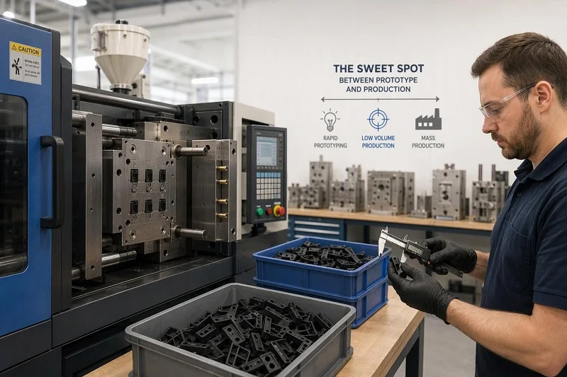
Conformity is demonstrated with documents, not assurances. A buyer should expect a defined evidence pack with each tool and each shipment, and should review it before releasing a tool to production rather than after the first order ships.
First-Article Inspection and Dimensional Reporting
A first-article inspection report measures the initial parts against every dimension and tolerance on the drawing, including GD&T callouts, and records the result feature by feature. Review it before production release: it is the point where a steel correction is still a planned rework rather than a schedule crisis.
Material Certificates and Traceability
Resin lot traceability links a shipment back to the grade and batch actually molded. A certificate of analysis confirms the supplied grade, and the processing record should show drying conditions and any regrind percentage used. For critical or regulated parts, uncontrolled regrind content and moisture are common causes of unexplained property loss.
Quality Management Systems and Regulated Industries
ISO 9001:2015 is the general quality management framework, and ISO has since published a 2026 edition that replaces it, with a transition period for certified organizations. ISO 13485:2016 is tailored to medical devices and emphasizes regulatory requirements, risk management and process validation. The U.S. FDA quality system regulation that became effective on February 2, 2026 incorporates ISO 13485:2016 by reference.
Cost Drivers in Custom Injection Molded Parts Projects
Money in a molding project sits in four places: the tool, the resin, the machine time and everything done to the part after ejection. Separating them makes the levers visible, because the largest ones are usually decided in design rather than in negotiation.
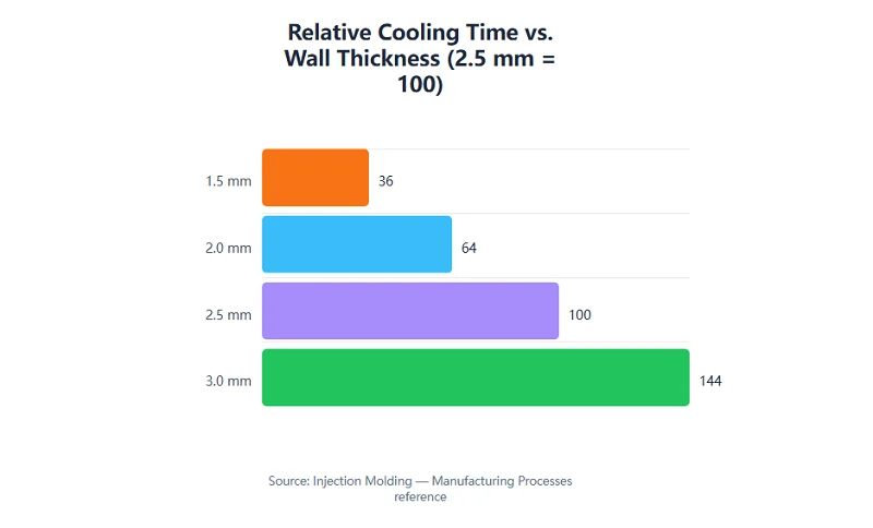
Cooling time scales with the square of wall thickness. Illustrative calculation using the stated relationship: reducing a 2.5 mm wall to 2.0 mm cuts the cooling term to about 64% of its original value, roughly a one-third reduction. Actual cycle time also includes fill, pack and eject phases.
Tooling Cost and Cavitation
Cavity count is the first lever: each added cavity raises tool price but spreads the mold investment over more parts per cycle. Side actions, hot runners and high-polish finishes add cost without adding output. Typical industry tooling ranges run from about $5,000 for a simple single-cavity mold to $100,000 or more for complex multi-cavity steel, so the break-even volume shifts accordingly.
Part Cost, Cycle Time and Wall Thickness
Cooling usually accounts for 50–80% of cycle time, and cooling time scales with the square of wall thickness. Trimming a 2.5 mm wall to 2.0 mm cuts the cooling term by roughly a third — more leverage than any barrel-temperature adjustment. Wall reduction is therefore the highest-value cost change available in part design.
Secondary Operations, Inspection and Logistics
Assembly, decoration, insert installation, inspection level and packaging are frequently underestimated at quotation. A part with a low molded price can carry a much higher delivered cost once post-machining, finishing and full dimensional inspection are added. Evaluate each process on total delivered cost, not the primary unit price alone.
Sourcing Custom Injection Molded Parts from an Overseas Manufacturer
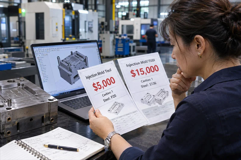
Cross-border sourcing works when the information flow is as disciplined as the tool build. What you send, what you confirm in writing and how you review trial samples determine whether the mold arrives ready to run on your press with your resin.
Information to Prepare Before Requesting Quotes
Send 3D CAD and 2D drawings with tolerances, annual and monthly volumes, resin preference or performance requirements, cosmetic class, regulatory constraints, target date and destination. Each item changes the quote: volume sets cavitation, cosmetic class sets polishing, and destination affects packaging and freight.
Machine, Resin and Documentation Requirements to Confirm
Settle the receiving press data sheet and the exact resin grade with filler content before steel is released; both are commonly missing inputs that become assumptions in the quote. Request the dimensional report, steel certificates, cooling layout and trial parameters with the tool, and material documentation with each shipment.
Managing Communication During Tool Build and Trials
Agree a written design freeze, ask for weekly build updates, and review trial samples with photographs plus dimensional data rather than images alone. Close the loop with a written approval before production release, so both sides work from the same record.
Choose NOBLE to Support Your Custom Injection Molded Parts Project
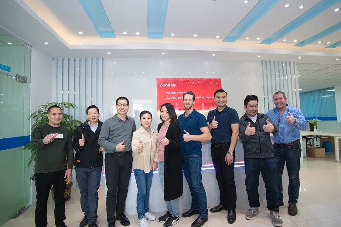
NOBLE is a Sino-British joint venture and Chinese manufacturing partner with more than ten years of professional manufacturing and rapid prototyping experience. We support customers from prototype through mass production, and our stated service scope runs from design to assembly rather than production alone. NOBLE holds ISO 9001:2015 and ISO 13485:2016 certification.
From Design and Prototyping to Mass Production
NOBLE can take part in design input, prototyping, tooling coordination, production and assembly as one continuous program. Keeping those phases with a single partner reduces the handoff risk that appears when a prototype shop, a toolmaker and a molder each interpret the drawing differently.
Service Capabilities and Quality Certifications
NOBLE reports rapid lead times, with parts finished in as little as 7–10 days, and a professional quote within 24 hours of an RFQ submitted with the needed information. In-house capabilities cover design, prototyping and mass production, backed by a full set of inspection equipment and an overall quality control system. NOBLE’s certifications are ISO 9001:2015 and ISO 13485:2016.
FAQs About Custom Injection Molded Parts
Short answers to the questions buyers ask most often about custom injection molded parts.
How Do I Know Whether My Part Should Be Injection Molded Rather Than Machined or 3D Printed?
Screen on annual volume, tolerance, material and design maturity. Below roughly 1,000 parts, machining or printing usually wins; above that, molding’s unit economics take over. See the process comparison section for the full table.
What Information Do I Need to Prepare Before Requesting Quotes for Custom Injection Molded Parts?
3D CAD and toleranced 2D drawings, annual and monthly volumes, resin or performance requirements, cosmetic class, regulatory constraints, target date and destination — the package described in the sourcing section.
Which Resin Family Fits My Temperature, Chemical and Mechanical Requirements?
Identify the dominant service requirement first, shortlist a tier — commodity, engineering or high-performance — then verify secondary requirements against the specific grade data sheet. The material section explains why a data sheet alone is not enough.
What Happens Between Approving a Design and Receiving Production Parts?
DFM review, design freeze, tool design and build, T1 trial, sample approval, validation, production and secondary operations — the workflow set out in the step-by-step process section.
How Do Prototype, Bridge and Production Tooling Differ and When Is Each Appropriate?
Prototype tooling validates design; bridge tooling supplies saleable parts while the production mold is built; production tooling serves sustained volume. Choose by design maturity and validated demand, as the tooling section explains.
What Does NOBLE Offer for a Custom Injection Molded Parts Project?
NOBLE offers design-to-assembly service scope, support from prototyping through mass production, rapid quotation and lead times, in-house inspection and quality control, and ISO 9001:2015 and ISO 13485:2016 certification.