Microfluidic CNC machining solves the hard problem of making tiny features with great accuracy. The microfluidics market grows by about 20% each year until 2030, which raises the need for better production methods. Four main methods lead this field: micromilling, micro-drilling, micro-grinding, and micro-EDM. Each of these methods has its own pros and cons. The process uses computer numerical control milling to shape materials exactly. These methods each fit different jobs. Micromilling works well for channels. Micro-drilling handles through-holes. Micro-grinding gives smooth surfaces. Micro-EDM works on hard metals. Your choice depends on materials, cost, and design complexity. Each method brings specific strengths.
Microfluidic CNC Machining Overview
Comparing CNC to Other Fabrication Methods
Soft lithography is the top choice in academic research labs. It works by casting polydimethylsiloxane onto a master mold. For simple channel designs, soft lithography works well. But it has clear limits. Soft lithography requires a clean room. Each new design also needs a fresh mold. It struggles with 3D shapes. Soft lithography for polydimethylsiloxane-based devices is still a common method. Yet it does not scale up easily for mass production. That keeps soft lithography mostly in prototyping. The polydimethylsiloxane material itself can be tricky. It absorbs some solvents and swells over time.
Hot embossing and injection molding handle high-volume fabrication. But they need costly metal tooling. The high upfront cost makes them poor for small batches. 3D printing offers design freedom for rapid prototyping. However, 3D printing often leaves rough surfaces. Those rough surfaces disrupt fluid flow in microfluidic devices.
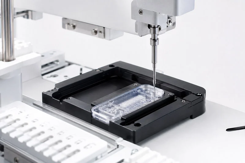
CNC machining fills the gap between these techniques. It provides good precision without high tooling costs. For fabrication of PCB-based microfluidics, CNC micro-milling is a standout. The fabrication process uses standard tools. No clean room is needed for fabrication. This makes fabrication faster and cheaper. Quality stays steady across many parts. Many teams pick CNC for fabrication of prototypes and medium runs. These bridging techniques make CNC a practical option.
Key Equipment Requirements
CNC machining for microfluidics demands special equipment. The most critical part is a high-speed spindle. Here are the key specifications:
| Specification | Value |
| Maximum spindle speed | 60,000 RPM |
| Spindle runout | < 1 µm |
| Power rating | 1.5–3.0 kW |
| Cooling system | Liquid-cooled |
| Dynamic balancing | Class G1.0 |
The 60,000 RPM speed lets you cut small features cleanly. Runout under 1 µm keeps every cut precise. The liquid cooling system holds accuracy during long runs. Class G1.0 balancing cuts down on harmful vibration. These specs work together for reliable results. End mills as small as 0.2 mm create micro-scale channels. Five-axis capability adds flexibility for complex shapes. The machine needs sub-micrometer precision to meet tight tolerances. These needs make microfluidic CNC machining different from standard CNC work. The machine frame must be rigid. Any vibration shows up in the final part. Shop temperature control also matters. Even small temperature shifts change material expansion and cut sizes.
Balancing Speed and Precision
Speed and precision pull against each other. Faster cuts remove material quickly. But fast cuts can bend the tool. Tool bending hurts accuracy. Slower cuts give smoother surfaces. But they take longer. The trick is finding the sweet spot. For microfluidic channels, surface quality matters most. A rough surface traps bubbles. Bubbles ruin experiments. So precision often beats speed. CNC machining for microfluidics puts accuracy first. Machine setup and tool choice both affect this balance. For rapid prototyping runs, CNC offers a great balance. The process can switch materials quickly. Feed rate matters too. Too fast a feed rate leaves rough edges. Too slow a feed rate wastes time. The right balance depends on the material. Softer plastics can handle faster speeds. Harder metals need slower cuts. Your part’s shape also plays a role. Deep channels need different settings than shallow ones. The goal is the best surface finish in the shortest time. Skilled machinists know how to adjust settings for each job.
Microfluidic CNC Machining Processes
Micromilling for Channel Fabrication
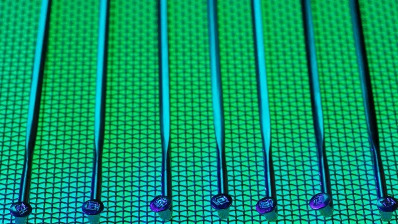
Micromilling is the main tool for making microfluidic channels. It uses tiny end mills, sometimes only 0.2 mm wide, spinning fast to cut exact paths into materials. The cutting action removes material layer by layer. It leaves clean, well-defined channels that guide fluid flow where you need it.
What can micromilling actually achieve? Think about a herringbone mixer. It is a common device for mixing fluids at small scales. Researchers have made these mixers with channel depths of 100 μm and widths up to 1 mm. That combination works well for many lab-on-a-chip uses. The platform works for channels at least 100 μm deep without needing special surface treatments. Below that depth, you start having problems.
The smallest channel width depends on your milling tool’s diameter. You cannot cut a channel narrower than the tool. With positioning precision under 28 μm, the mill handles channels at scales of several hundred micrometers quite easily. That makes micromilling ideal for devices where channels need to be visible to the naked eye or where larger fluid volumes matter.
Five-axis CNC micro-milling takes this ability even further. With five axes of movement, the cutting tool can approach the workpiece from many angles. This flexibility lets you create complex three-dimensional channel networks. Instead of flat, two-dimensional layouts, you can design channels that dip, rise, and cross at different depths. Such designs open new possibilities for mixing, separation, and reaction chemistry within a single chip.
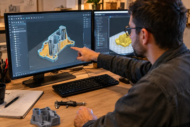
The real advantage of micromilling is its directness. You design your channel geometry in CAD software, generate toolpaths, and cut. No master mold is required. No clean room is needed. This direct workflow makes micromilling perfect for iterative design cycles where you test, refine, and test again.
Micro-Drilling and Micro-EDM
While micromilling carves open channels, micro-drilling makes precise through-holes. These holes connect different layers of a microfluidic device or link the chip to external tubing. Standard drilling struggles at these tiny scales. Drill bits flex and wander off course. Micro-drilling solves this with specialized equipment and careful control of parameters.
For features that are too hard for even micro-drilling, micro-EDM steps in. Electrical discharge machining removes material using controlled sparks. The tool never touches the workpiece. Instead, electrical erosion does the work. This makes micro-EDM perfect for high-aspect-ratio features in hard metals. You can create deep, narrow holes that would break conventional drill bits. The process works on any electrically conductive material, no matter how hard it is.
Micro-EDM excels where other methods fail. Stainless steel, titanium, and hardened tool steel all respond well. The trade-off is speed. Micro-EDM removes material slowly compared to milling. But for those impossible geometries, it remains the only option. Many manufacturers combine techniques. They use micromilling for channels and micro-EDM for the trickiest holes.
Combined 3D Printing and CNC Methods
Why choose between 3D printing and CNC machining when you can use both? This hybrid approach uses the strengths of each technique. 3D printing excels at creating complex internal structures and organic shapes. CNC machining delivers precise surfaces and tight tolerances. Together, they cover each other’s weaknesses.
The workflow typically starts with 3D printing. You print the overall device structure, including internal cavities and complex geometries that would be difficult to mill. Then comes CNC machining. A finishing pass removes the rough surface layer left by printing. This step smooths the channels and brings critical dimensions into spec.
This combination proves especially valuable for rapid prototyping. You can iterate on overall design quickly using 3D printing. Then refine the final version with CNC machining. The approach also suits microfluidic chip fabrication techniques that demand both geometric freedom and surface quality.
Droplet generator chips are a good example. These devices create uniform droplets for uses like drug delivery and single-cell analysis. The channel geometry must be precise to control droplet size. The surface finish must be smooth to prevent droplets from sticking. A printed chip alone often fails on surface quality. A machined chip alone struggles with complex junction geometries. The hybrid approach gives both.
For microchambers and other microfluidic features, this combined strategy offers real flexibility. You can print the chamber geometry. Then machine the sealing surfaces to ensure leak-free operation. The result combines design freedom with manufacturing precision.
These fabrication techniques each serve different purposes. Micromilling handles channels with speed and precision. Micro-drilling and micro-EDM tackle holes that push conventional limits. Hybrid printing and machining approaches give you the best of both worlds. When you need expert guidance on which path suits your project, companies like NOBLE, an outstanding manufacturer in China, help clients choose. Their team supports both prototyping and mass production. They ensure your microfluidic CNC machining project moves smoothly from concept to finished device.
Microfluidic CNC Machining Materials
Thermoplastics for Microfluidics
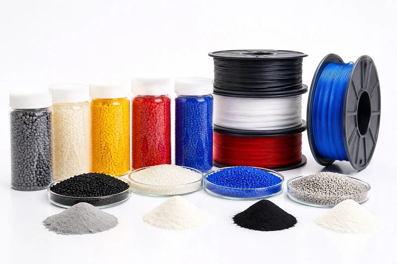
Thermoplastics are the top choice for microfluidic CNC machining. They cut cleanly, cost less than metals, and let light pass through. That helps many experiments. The common materials for this process are:
- PMMA (polymethyl methacrylate)
- Polycarbonate
- COC/COP (cyclic olefin copolymer/polymer)
PMMA is the cheap and reliable option. It machines well, makes smooth channels, and lets light through. Many labs pick PMMA for prototyping because it is easy to get and low cost. Polycarbonate is tougher. It can handle higher heat and resists cracks better than PMMA. COC and COP are different. They have low autofluorescence and good chemical resistance. These traits matter when you use fluorescence tests. The downside? COC costs more and can break easily during cutting.
Each material acts differently with cutting settings. PMMA likes high spindle speeds and sharp tools. Polycarbonate can form stringy burrs if feed rates are too fast. COC needs good chip removal to stop melting. Your choice of plastic shapes every step of the making process.
Metals and Other Substrates
Some microfluidic devices need metal instead of plastic. Stainless steel resists rust and is strong. Aluminum is light and spreads heat well. Titanium is safe for the body, so medical devices use it. These metals show up in implantable drug systems and high-pressure flow reactors.
Cutting metals for microfluidics is harder than cutting plastics. Tools wear out faster. Heat builds up more quickly. To get smooth surfaces, you need slower speeds and good coolant. But the benefit is toughness. Metal chips can be cleaned, sterilized, and used with harsh chemicals. Plastic chips break down in those conditions.
Metal parts also allow built-in electrodes or heaters. You can cut channels right into a metal block, then seal a clear window on top. This mix supports uses that combine fluid handling with electrical sensing. The making process is different from plastic, but the design ideas are the same.
Material Impact on Surface Finish
Surface finish controls how fluids move inside your channels. Rough surfaces make turbulence and trap air bubbles. Smooth surfaces let fluids flow steadily. For optical detection, surface quality affects signal clarity. Light that scatters off rough walls ruins sensitive readings.
Thermoplastics usually give better surface finishes than metals. PMMA can make mirror-like channels with the right tools. Metals need extra steps like polishing to match that smoothness. But metal surfaces can be changed with chemicals. You can coat them to change how they react with water or add functional layers.
Material hardness also affects how tight tolerances you can hold. Soft plastics bend under cutting pressure, making it harder to keep exact sizes. Harder metals hold dimensions better but wear out tools faster. This balance between ease of cutting and precision guides your material choice. For most microfluidic CNC machining projects, the material choice depends on what your use needs. Clarity, chemical resistance, strength, and cost all compete for importance. Knowing these trade-offs helps you pick the right base material the first time.
Microfluidic CNC Machining Design
Microfluidic Chip Design Rules
Good microfluidic chip design starts with knowing what your tools can do. Microfluidic CNC machining needs care from the very first drawing. The smallest end mill you can use is about 0.2 mm wide. That sets a hard limit on channel width. You cannot cut a channel smaller than your tool. So plan your shape around that number from the start.
Think about droplet generator chips. These devices make same-sized droplets for drug delivery and single-cell analysis. Their channel joints must be exact. Small errors change droplet size. The fabrication tolerances you pick directly affect how it works. The table below shows what different fabrication methods can do:
| Fabrication Method | Minimum Feature Size (μm) |
| Photolithography | <1 |
| Micromachining | 50 |
| Laser ablation | 1 |
| 3D printing | 100 |
| Chemical etching | <1 |
Micromachining lands at 50 μm. That works for many droplet generators. But you need to design around that limit. Leave space for tool access. Avoid sharp inside corners that a round end mill cannot reach. These microfluidic features need extra care. Every corner in your channel will have a curve equal to half your tool’s width. Plan for that curve.
Toolpath Strategies for Small Features
Toolpath strategy decides whether your microfluidic chip comes out clean or full of burrs. Burrs are tiny raised edges of material. They ruin fluid flow and trap bubbles. The right toolpath reduces them.
Climb milling is your best choice here. The tool spins in the feed direction. This cuts cleaner than regular milling. It leaves fewer burrs on the channel edges. For plastics like PMMA, climb milling makes a big difference. These methods keep your channels clean and exact.
Tool bending is another problem. A 0.2 mm end mill bends easily under cutting pressure. That bending causes slanted walls and wrong depths. The fix is to take shallow cuts. Remove only a small amount of material each time. Many light cuts beat one heavy cut. This is one of the best methods for microchannel making that skilled machinists follow.
Managing Aspect Ratio and Tolerance
Aspect ratio means channel depth divided by channel width. Deep, narrow channels have high aspect ratios. They cause problems. Tools bend more. Chips get stuck. Heat builds up. For most microfluidics work, keep aspect ratios below 3:1. That means a 300 μm deep channel needs at least 100 μm width. This rule stops many common mistakes.
Tolerance matters for leak-free sealing. When you bond a cover layer onto your channels, the mating surfaces must match. A tolerance of a few micrometers keeps the seal tight. But tighter tolerances cost more time. Every extra pass adds machining hours. Balance your need for exactness against your budget. This trade-off shapes every making decision.
Surface finish also affects sealing. Rough surfaces create tiny gaps. Fluids seep through those gaps. For good seals, aim for a smooth finish on all bonding surfaces. The channel walls themselves need less polish. Fluid flow only cares about big roughness, not tiny texture.
These microfluidic chip-making methods work together. Design rules set your limits. Toolpath strategies control quality. Aspect ratio and tolerance management make sure your device works. Getting all three right takes practice. But the reward is a microfluidic chip that works the first time. When you need expert help with microfluidic chip design, makers like NOBLE offer guidance. Their engineers check your design before cutting begins. That check finds problems early. It saves time and money in the long run.
Microfluidic CNC Machining Precision
Achieving Tight Tolerances
Tight tolerances are essential for microfluidic devices. When you seal a cover layer onto a channel plate, tiny gaps turn into leaks. Fluids escape. Experiments fail. For leak-free sealing, mating surfaces must match within a few micrometers. That level of precision separates professional fabrication from hobby work.
Sub-micrometer tolerances sound impossible for cutting tools. Yet modern CNC machines hold them regularly. The secret lies in machine rigidity and thermal stability. A rigid frame resists bending under cutting forces. Temperature-controlled shops prevent material expansion. Even a few degrees of shift changes part dimensions. Skilled machinists monitor both factors throughout the run.
The fabrication process also depends on tool condition. A worn end mill cuts differently than a fresh one. It deflects more. It leaves rougher edges. Many shops replace tools after set intervals, not when they fail. This practice keeps quality consistent across every part. For microfluidics, consistency matters as much as absolute accuracy. Every chip in a batch must perform the same way.
Surface Roughness and Optical Clarity
Surface roughness directly affects fluid behavior. Rough channel walls create turbulence. They trap air bubbles. They disrupt laminar flow that microfluidic experiments depend on. The target for most devices is a very smooth surface finish. Achieving this requires sharp tools, proper speeds, and light final passes.
Optical clarity adds another layer of complexity. Many microfluidic chips rely on microscopy or fluorescence detection. Light must pass through channel walls without scattering. A rough surface scatters light. It blurs images. It weakens signals. For PMMA and other transparent thermoplastics, surface finish determines whether you can see your experiment clearly.
Getting these smooth surfaces takes deliberate effort. The fabrication strategy includes a roughing pass followed by finishing passes. Each finishing pass removes less material. The final pass might cut only a few micrometers deep. This approach leaves a mirror-like finish on plastics. Metals need additional steps like polishing or lapping to reach similar smoothness. The extra time pays off in better experimental results.
Role of High-Speed Spindles
High-speed spindles are the heart of precision microfluidic CNC machining. Standard spindles spin at 10,000 to 20,000 RPM. That speed works for large parts. It fails for micro-features. Small end mills need much higher surface speeds to cut cleanly. At low RPM, a 0.2 mm tool rubs instead of cutting. Rubbing generates heat. It dulls the tool. It leaves a poor surface finish.
Spindles reaching 60,000 RPM solve this problem. At that speed, even tiny tools achieve proper cutting velocity. Material shears away cleanly. Burrs stay minimal. Channel walls come out smooth. The spindle’s runout also matters. Runout below 1 µm keeps every flute cutting evenly. Higher runout means one flute does more work. That causes vibration and poor finish.
Liquid cooling keeps the spindle stable during long runs. Heat from high-speed rotation would otherwise cause drift. Class G1.0 dynamic balancing minimizes vibration. These specifications work together. They let machinists hold tight tolerances while achieving smooth surfaces. Without a proper high-speed spindle, precision microfluidic fabrication simply is not possible. The equipment investment directly determines the quality ceiling for your devices.
These precision techniques apply across different fabrication methods. Whether you machine thermoplastics or metals, the principles stay the same. Sharp tools, proper speeds, and stable machines produce reliable microfluidic chips. When you need this level of quality, working with an experienced manufacturer ensures your devices meet performance expectations.
NOBLE for Microfluidic CNC Machining
Our Manufacturing Capabilities
NOBLE works with both metals and plastics for microfluidic devices. Their high-speed CNC machines are built for precision work. Tiny end mills, some just 0.2 mm wide, cut channels in PMMA, polycarbonate, and COC. The same machines handle stainless steel, aluminum, and titanium for metal parts. Every machine keeps positioning accuracy below one micrometer. That precision makes NOBLE a dependable partner for microfluidic fabrication.
The team uses all the main fabrication methods from this guide. Micromilling makes smooth channels. Micro-drilling adds exact through-holes. Micro-EDM handles the toughest metal features. Having all these methods in one place saves time. You do not need to send your design to different shops. NOBLE manages the whole fabrication process from start to finish.
Quality Certifications
Quality matters in microfluidics. One small flaw can ruin an experiment. NOBLE holds ISO 13485 certification. This standard ensures that processes stay consistent. It means every part receives the same careful treatment.
The ISO 13485 certification matters most for healthcare uses. Many microfluidic devices for healthcare need strict quality control. NOBLE meets those standards. The quality system tracks every step of fabrication. Raw materials get checked. Machine settings get recorded. Final parts get measured. This system catches problems before they reach your hands.
Full-Service Solutions from Design to Assembly
NOBLE does more than cut parts. The company offers full-service support from design through assembly. This full-service approach to microfluidic CNC machining brings several benefits. Consistent quality comes from controlling every step with minimal defects. High manufacturing yields keep costs down while maintaining device reliability. Device miniaturization leads to smaller, more efficient designs. Faster time-to-market happens because scalable processes support progression from clinical trials to commercial production. Regulatory compliance stays smooth with ISO 13485 certification and adherence to global standards like FDA, MDR, and IVDR.
The engineering team checks your design before any cutting starts. They look for common problems like tool access, sharp corners, and aspect ratio issues. Their feedback saves time and money. Instead of finding a problem during machining, you fix it in the design stage. This early review improves the whole fabrication process.
After machining, NOBLE offers assembly services. Channel bonding, port installation, and leak testing all happen in-house. You receive a finished device, not just a box of parts. This full-service model works for both prototyping and production runs. Whether you need five chips or five thousand, the same team manages your project.
The mix of metal and plastic processing, quality certifications, and end-to-end service makes NOBLE a strong partner for microfluidic CNC machining projects. When your device moves from concept to production, having a single partner simplifies the journey.
Each method serves a purpose. Micromilling creates channels in plastics. Micro-drilling makes clean holes. Micro-EDM tackles hard metals. Your fabrication choice depends on feature size, material, and production volume.
For rapid prototyping of plastic chips, micromilling often wins. For high-aspect-ratio holes in metals, micro-EDM excels. These fabrication techniques complement each other. Many projects combine them with 3d printing for complex geometries. Healthcare devices demand precision fabrication. Quality fabrication matters at every step of microfluidics work. Rapid prototyping benefits from CNC’s flexibility.
Partnering with an experienced manufacturer simplifies fabrication. NOBLE offers end-to-end support for microfluidic cnc machining projects. Their engineers review designs before cutting begins. Contact NOBLE today for a consultation.
FAQs of Microfluidic CNC Machining
What is the best method for making microfluidic channels?
Micromilling works best for most channel work. It uses tiny end mills down to 0.2 mm. The fabrication process creates clean paths in plastics like PMMA and polycarbonate. No master mold needed. No clean room required.
Can I use CNC machining for prototyping?
Yes. CNC machining works great for prototyping. This fabrication method skips expensive tooling. You can test designs, fix problems, and cut new parts the same day. That speed helps teams iterate faster.
What materials work best for this type of work?
PMMA, polycarbonate, and COC are top choices. They cut cleanly and let light through. For tougher jobs, stainless steel, aluminum, and titanium work well. These fabrication techniques each need different cutting settings.
How do I get smooth channel surfaces?
Use sharp tools and high spindle speeds up to 60,000 RPM. Take light finishing passes. Climb milling reduces burrs. Target a smooth surface finish for best flow. The fabrication process needs careful control.
What is the smallest channel size I can make?
The smallest channel width equals your end mill diameter. Tools as small as 0.2 mm exist. So channels can be 200 µm wide. Channel depth depends on aspect ratio limits. This fabrication method works well for many microfluidics projects.
Do I need a clean room for CNC machining?
No. CNC machining does not need a clean room. That is a big advantage over soft lithography. You can set up a CNC machine in a regular workshop. This saves time and money for microfluidics work.
How does micro-EDM compare to micromilling?
Micro-EDM removes material with sparks. The tool never touches the workpiece. It works on hard metals like stainless steel. But it is slower than micromilling. Use it for holes that break drill bits.