Introduction: The Gateway to Hardware Innovation
Imagine holding your groundbreaking product concept in your hands for the first time—feeling its weight, testing its mechanisms, presenting it to investors, or putting it through real-world conditions. This transformative moment, where digital designs become physical reality, is made possible through sheet metal prototype fabrication. In today’s fast-paced hardware development landscape, the ability to quickly and accurately produce functional prototypes isn’t just an advantage—it’s a necessity for survival and success.
Sheet metal prototyping stands as the critical bridge between conceptual design and mass production, enabling innovators across industries—from aerospace startups to medical device developers—to validate, refine, and perfect their designs before committing to expensive production tooling. This comprehensive guide explores every aspect of sheet metal prototype fabrication, providing the knowledge you need to navigate this essential phase of product development successfully.
Chapter 1: Understanding Sheet Metal Prototyping
What is Sheet Metal Prototype Fabrication?
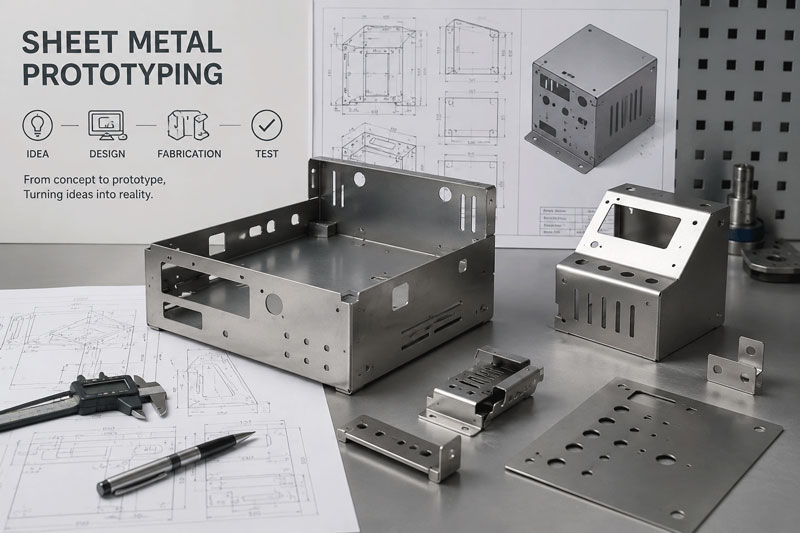
Sheet metal prototype fabrication refers to the specialized process of creating functional, dimensionally accurate sheet metal parts and assemblies in low volumes for design validation, testing, and market evaluation. Unlike mass production methods that rely on dedicated tooling and high-volume optimization, prototype fabrication prioritizes speed, flexibility, and precision for small batch production.
Core Characteristics of Prototype Fabrication:
- Low Volume Focus: Typically 1 to 100 pieces
- Rapid Turnaround: Days or weeks instead of months
- Design Flexibility: Easy accommodation of design changes
- Cost-Effective Tooling: Minimal or no hard tooling investment
- High Precision: Meeting tight tolerances for validation purposes
The Critical Role of Prototyping in Product Development
Risk Mitigation Through Physical Validation
Research indicates that products validated with functional prototypes experience 67% fewer design-related issues during production and 82% higher market acceptance rates. Prototyping enables:
- Identification and resolution of design flaws before tooling investment
- Verification of manufacturing feasibility and assembly processes
- Validation of material selection and performance characteristics
- Demonstration of product functionality to stakeholders and investors
The Cost-Saving Imperative
While prototype fabrication represents an investment, it’s dwarfed by the potential costs of:
- Production tooling modifications (typically 5-15x more expensive than prototype changes)
- Production delays and missed market windows
- Product recalls due to undetected design flaws
- Lost competitive advantage from delayed market entry
Chapter 2: Prototype Fabrication Methods and Technologies
Laser Cutting for Prototypes
Technology Overview:
Laser cutting utilizes focused laser beams to melt, burn, or vaporize material with exceptional precision. Modern fiber laser systems offer superior speed and quality for prototype applications.
Prototype-Specific Advantages:
- Zero Tooling Costs: No physical tools required
- Extreme Flexibility: Quick design changes without tool modifications
- Excellent Precision: Tolerances as tight as ±0.004″ (0.1mm)
- Complex Geometries: Intricate shapes and fine details are easily achieved
- Material Versatility: Cuts various metals, including stainless steel, aluminum, and copper
Typical Applications:
- Complex flat patterns and profiles
- Ventilation grilles and decorative elements
- Structural components with intricate cutouts
- Brackets and mounting plates
- Enclosure panels and covers
Technical Specifications:
- Maximum Thickness: Up to 1″ (25mm) for some materials
- Positioning Accuracy: ±0.001″ (0.025mm)
- Minimum Feature Size: 0.004″ (0.1mm) kerf width
- Edge Quality: Excellent with minimal heat-affected zone
CNC Punching for Prototype Production
Technology Overview:
CNC punching uses programmable turret presses to create holes, shapes, and forms in sheet metal through mechanical force.
When to Choose Punching for Prototypes:
- Standard Features: When parts include common hole sizes and shapes
- Forming Operations: For louvers, countersinks, and embossed features
- Medium Volume Needs: 10-50 pieces where laser setup times become inefficient
- Cost Efficiency: When standard tooling can be utilized effectively
Advantages for Prototyping:
- Integrated Forming: Creates formed features in the same operation
- Tool Library Access: Extensive standard tool availability
- Good Edge Quality: Clean edges with minimal burr
- Reasonable Speed: Faster than laser for certain patterns
Limitations:
- Tooling Constraints: Limited by available tool sizes and shapes
- Setup Requirements: Tool setup needed for each job
- Geometric Constraints: Less flexible for complex contours than laser
CNC Press Brake Forming
Technology Overview:
Modern CNC press brakes use computer-controlled backgauges and ram positioning to achieve precise bends in sheet metal components.
Prototype-Specific Capabilities:
- Quick Setup: Digital tool setup and program loading
- High Accuracy: Angular tolerances of ±0.5° are achievable
- Flexible Tooling: Adjustable for various materials and thicknesses
- Complex Bending: Multiple bends in single setups
Critical Considerations for Prototype Bending:
- Material Springback: Compensation calculations for different materials
- Bend Sequence Optimization: Planning for accessibility and accuracy
- Tool Selection: Matching tools to material and radius requirements
- Prototype-Specific Challenges: Small batches require special attention to consistency
Advanced Features for Prototypes:
- 3D Bending: Complex multi-plane bends
- Automatic Tool Change: For varied prototype requirements
- Laser-Angle Measurement: Real-time angle verification
- Collision Avoidance: Software protection for complex parts
Waterjet Cutting for Specialized Prototypes
Technology Overview:
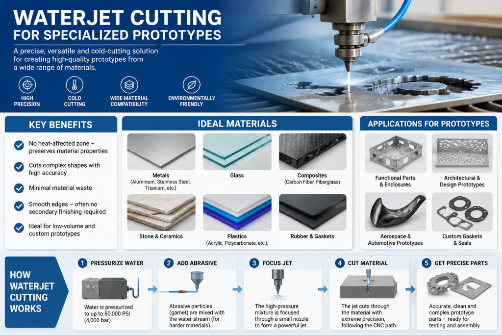
Waterjet cutting uses high-pressure water mixed with abrasive particles to cut through materials without heat input.
Prototype Applications:
- Heat-Sensitive Materials: Where thermal distortion must be avoided
- Thick Materials: Up to 6″ (150mm) thickness capability
- Composite Materials: Mixed material cutting
- Delicate Components: Where clamping force is a concern
Advantages:
- No Heat-Affected Zone: Critical for certain materials and applications
- Material Versatility: Cuts metals, composites, glass, and stone
- Environmental Benefits: No toxic fumes or thermal distortion
- Precision Capability: Good accuracy for most prototype needs
Additive Manufacturing Integration
Hybrid Approaches:
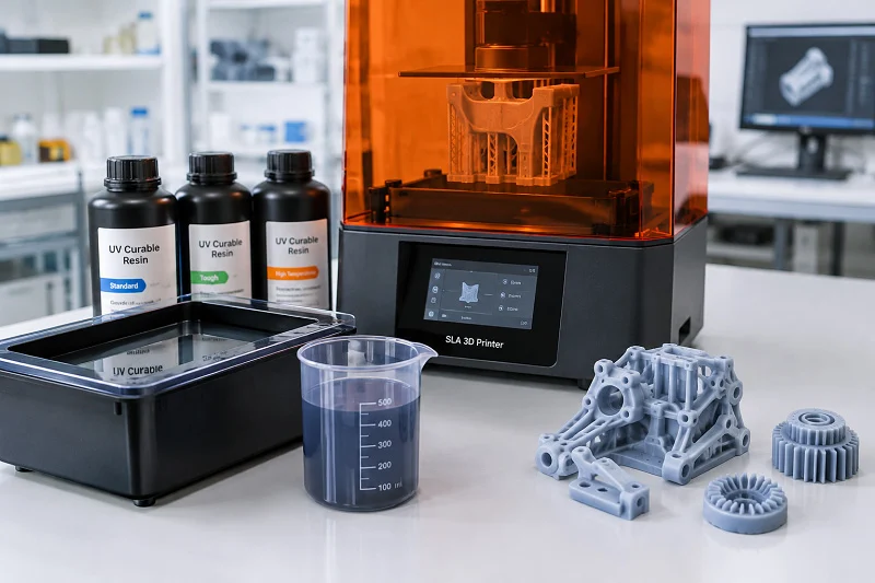
Increasingly, sheet metal prototyping incorporates 3D printing for:
- Complex Brackets and Mounts: Where sheet metal is impractical
- Assembly Jigs and Fixtures: Custom tooling for prototype assembly
- Non-Structural Components: Decorative or low-stress elements
- Rapid Iteration: Quick design changes without metal fabrication
Chapter 3: Materials for Sheet Metal Prototypes
Commonly Used Materials
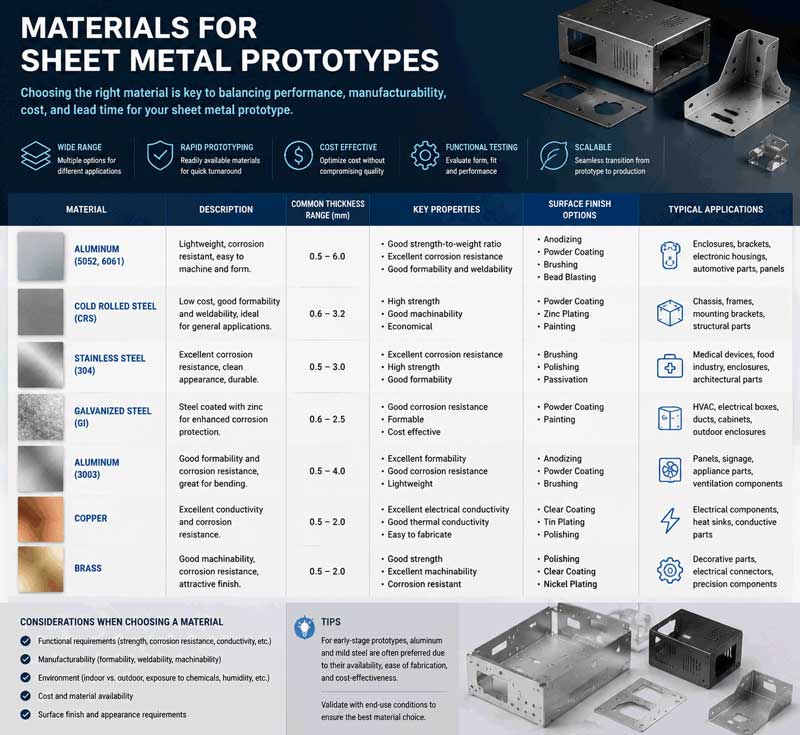
Aluminum Alloys:
- 5052-H32: Excellent corrosion resistance, good formability
- 6061-T6: High strength-to-weight ratio, good machinability
- 3003: Superior formability, good weldability
- Prototype Considerations: Lower cutting forces, easier forming than steel
Stainless Steels:
- 304: Most common, good corrosion resistance and formability
- 316: Superior corrosion resistance, marine and chemical applications
- 430: Magnetic, good formability, lower cost
- 17-4 PH: Precipitation hardening, high strength after heat treatment
Cold-Rolled Steels:
- 1018: General purpose, good weldability, and machinability
- CRS Grades: Various tempers and surface finishes available
- Prototype Advantages: Low cost, readily available, easy to work with
Copper and Brass:
- Copper C110: Excellent electrical and thermal conductivity
- Brass 260: Good corrosion resistance, decorative appearance
- Special Applications: Electrical components, decorative elements, heat exchangers
Specialty Materials:
- Spring Steels: For clips and retaining features
- Pre-Plated Materials: Galvanized, galvannealed options
- High-Strength Alloys: For demanding applications
- Exotic Alloys: Titanium, Inconel for specialized prototypes
Material Selection Guidelines for Prototypes
Performance-Driven Selection:
- Strength Requirements: Yield and tensile strength are needed
- Corrosion Resistance: Environmental exposure considerations
- Weight Constraints: Density and strength-to-weight ratio
- Thermal Properties: Conductivity and expansion coefficients
Manufacturing Considerations:
- Formability: Minimum bend radii and elongation characteristics
- Weldability: Compatibility with planned joining methods
- Surface Finish: Appearance and post-processing requirements
- Availability: Lead times and minimum order quantities
Cost Optimization Strategies:
- Standard Gauges: Using readily available thicknesses
- Common Alloys: Avoiding exotic materials when possible
- Size Optimization: Minimizing scrap through nesting
- Alternative Materials: Considering substitutes with similar properties
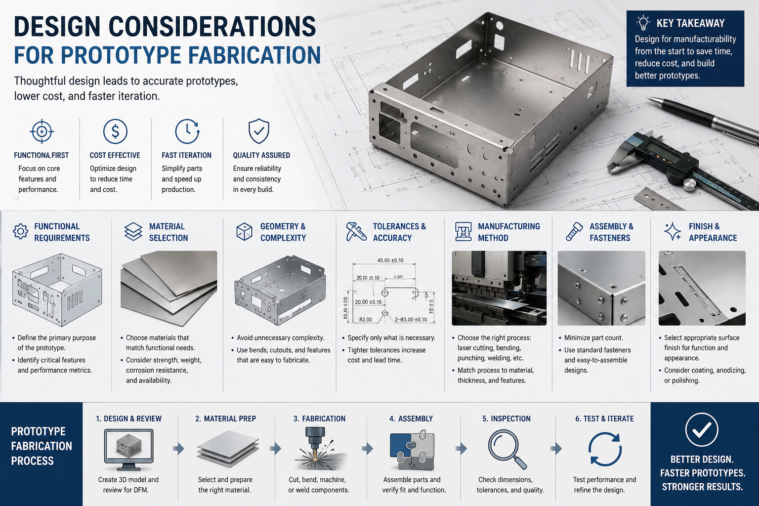
Chapter 4: Design Considerations for Prototype Fabrication
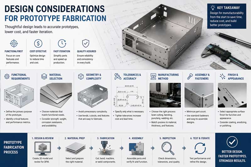
Design for Manufacturability (DFM) Principles
Key DFM Guidelines:
- Standardize Features
- Use common hole sizes and bend radii
- Standardize material thicknesses where possible
- Design for available tooling and capabilities
2. Optimize for Prototype Processes
- Design for laser cutting when quick changes are anticipated
- Consider punching for standard features in moderate volumes
- Plan for press brake accessibility and sequence
- Minimize Complexity
- Reduce the number of unique parts
- Simplify assembly requirements
- Standardize fasteners and hardware
Critical Design Elements:
Bend Design Considerations
- Minimum Bend Radius: Typically 1x material thickness for steel, 1.5x for aluminum
- Bend Relief: Proper relief cuts to prevent tearing
- Flange Length: Minimum of 4x material thickness plus bend radius
- Grain Direction: Consideration for anisotropic materials
Hole and Cutout Design
- Minimum Hole Size: Diameter equal to material thickness (practical minimum 0.040″)
- Edge Distance: Minimum 2x material thickness from hole to edge
- Slot Dimensions: Width equal to material thickness
- Nesting Efficiency: Designing for optimal material utilization
Formed Feature Design
- Louvers and Ribs: Proper clearances for tooling
- Countersinks and Embosses: Standard sizes and depths
- Hem and Seam Design: Proper allowances and clearances
- Special Features: Consider manufacturability early
Tolerance and Specification Guidelines
Standard Prototype Tolerances:
- Linear Dimensions: ±0.010″ (0.25mm) for most features
- Hole Locations: ±0.005″ (0.13mm) for precision applications
- Bend Angles: ±1° for standard bends
- Flatness: 0.010″ per inch (0.25mm per 25mm)
Critical Feature Specifications:
- Surface Finish Requirements: Specify if critical
- Burr Control: Direction and maximum allowable burr
- Edge Conditions: Deburring requirements and methods
- Cosmetic Surfaces: Areas requiring special handling
Chapter 5: The Prototype Fabrication Process
Step-by-Step Workflow
Phase 1: Design Review and Preparation
- Initial Design Assessment
- Review of CAD models and drawings
- DFM analysis and recommendations
- Material selection guidance
- Process selection optimization
2. Technical Documentation
- Creation of fabrication drawings
- Development of manufacturing instructions
- Quality requirement documentation
- Special process specifications
Phase 2: Programming and Setup
- CAD/CAM Programming
- Nesting optimization for material efficiency
- Toolpath generation and optimization
- Machine code generation and verification
- Simulation and collision checking
- Machine Setup
- Material selection and preparation
- Tool installation and calibration
- Program loading and verification
- First-article setup procedures
Phase 3: Fabrication Operations
- Cutting Operations
- Laser cutting or punching execution
- Quality verification during cutting
- Material handling and management
- Scrap control and management
2. Forming Operations
- Press brake setup and programming
- Bending sequence execution
- In-process inspection and adjustment
- Secondary forming operations
Phase 4: Secondary Operations
- Deburring and Edge Treatment
- Manual or automated deburring
- Edge breaking and smoothing
- Surface preparation for finishing
- Quality verification
2. Joining and Assembly
- Welding preparation and execution
- Fastener installation
- Adhesive bonding when required
- Sub-assembly creation
3. Surface Finishing
- Cleaning and preparation
- Painting or powder coating
- Plating or anodizing
- Special coatings and treatments
Phase 5: Quality Assurance and Delivery
- Inspection and Testing
- Dimensional verification
- Functional testing
- Material certification
- Documentation completion
- Packaging and Shipping
- Protective packaging design
- Documentation inclusion
- Shipping preparation
- Tracking and delivery coordination
Chapter 6: Quality Control for Prototype Fabrication
Inspection Methodologies
First Article Inspection (FAI)
- Complete Dimensional Verification: All features measured and documented
- Material Verification: Confirmation of material specifications
- Process Validation: Verification of manufacturing processes
- Documentation: Comprehensive inspection reports
In-Process Quality Control
- Setup Verification: Confirmation of machine settings
- Process Monitoring: Real-time quality parameter tracking
- Sample Inspection: Periodic part verification during production
- Statistical Process Control: For larger prototype batches
Final Inspection Protocols
- Visual Inspection: Surface quality and cosmetic evaluation
- Functional Testing: Assembly and operation verification
- Documentation Review: Complete record verification
- Customer Approval: Sample review and approval process
Measurement Equipment and Techniques
Standard Measurement Tools:
- Calipers and Micrometers: For linear dimensions
- Height Gauges: For vertical measurements
- Surface Plates: For flatness and parallelism
- Gauge Blocks and Pins: For hole verification
Advanced Measurement Systems:
- Coordinate Measuring Machines (CMM): For complex geometries
- Optical Comparators: For profile verification
- Laser Scanners: For free-form surfaces
- Portable CMMs: For large or awkward parts
Specialized Prototype Measurement:
- 3D Scanning: For reverse engineering and verification
- Digital Protractors: For angle measurement
- Surface Roughness Testers: For finish verification
- Hardness Testers: For material property verification
Chapter 7: Applications Across Industries
Aerospace and Defense
Prototype Requirements:
- Extreme Precision: Tight tolerances and exacting standards
- Material Expertise: Special alloys and composites
- Documentation: Complete traceability and certification
- Testing: Rigorous performance validation
Typical Applications:
- Structural brackets and mounts
- Avionics enclosures and racks
- Heat shields and thermal management components
- Test fixtures and ground support equipment
Medical Device Development
Special Considerations:
- Biocompatible Materials: FDA-approved materials and finishes
- Cleanliness Requirements: Special handling and processing
- Regulatory Compliance: Documentation for FDA submissions
- Sterilization Compatibility: Design for sterilization methods
Common Prototypes:
- Surgical instrument components
- Equipment housings and frames
- Implant trial components
- Diagnostic equipment parts
Consumer Electronics
Prototype Needs:
- Aesthetic Quality: Excellent surface finishes
- Fit and Finish: Precise assembly requirements
- Thermal Management: Heat dissipation considerations
- EMI/RFI Shielding: Electrical performance requirements
Applications:
- Device enclosures and chassis
- Heat sinks and thermal solutions
- Brackets and internal mounts
- Connector panels and interfaces
Automotive Development
Prototyping Requirements:
- Durability Testing: Components for testing and validation
- Form and Fit: Body panels and structural elements
- Material Validation: Testing new materials and processes
- Assembly Verification: Production process development
Typical Applications:
- Brackets and mounting hardware
- Test fixtures and prototypes
- Concept vehicle components
- Custom accessories and modifications
Industrial Equipment
Prototype Considerations:
- Function Over Form: Emphasis on performance
- Durability Requirements: Testing under real conditions
- Cost Optimization: Balancing performance and cost
- Manufacturability: Design for eventual production
Applications:
- Machine guards and safety equipment
- Custom brackets and supports
- Test equipment components
- Prototype machinery parts
Chapter 8: Cost Management and Optimization
Cost Structure Analysis
Direct Costs:
- Material Costs: Raw material purchase and processing
- Labor Costs: Programming, setup, and operation time
- Machine Time: Equipment utilization and depreciation
- Tooling Costs: Special tools or fixtures required
Indirect Costs:
- Engineering Time: Design review and preparation
- Quality Assurance: Inspection and testing
- Administrative Overhead: Project management and coordination
- Facility Costs: Space, utilities, and maintenance
Hidden Costs:
- Rework and Corrections: Design changes and modifications
- Delivery and Logistics: Shipping and handling
- Communication Overhead: Client meetings and coordination
- Risk Management: Contingency for unexpected issues
Cost Optimization Strategies
Design Optimization:
- Material Selection: Choosing cost-effective, appropriate materials
- Design Simplification: Reducing complexity without compromising function
- Standardization: Using common features and dimensions
- Nesting Efficiency: Maximizing material utilization
Process Optimization:
- Technology Selection: Choosing the most efficient fabrication methods
- Batch Optimization: Grouping similar operations
- Setup Minimization: Reducing changeover times
- Automation: Implementing automated processes where beneficial
Project Management Strategies:
- Clear Specifications: Reducing ambiguity and rework
- Efficient Communication: Streamlining information flow
- Proper Planning: Adequate time for each phase
- Contingency Management: Planning for expected challenges
Chapter 9: Timeline and Project Management
Typical Project Timelines
Standard Prototype Fabrication Timelines:
- Simple Parts: 3-5 business days
- Moderate Complexity: 5-10 business days
- Complex Assemblies: 10-20 business days
- Very Complex Projects: 3-4 weeks
Expedited Services:
- Rush Prototyping: 24- 48-hour turnaround available
- Priority Scheduling: Expedited queue placement
- Overtime Operations: Extended hours and weekend work
- Parallel Processing: Simultaneous operations where possible
Critical Path Activities
Design Phase (1-3 Days):
- Design review and DFM analysis
- CAD preparation and optimization
- Material selection and procurement planning
- Process selection and planning
Fabrication Phase (2-10 Days):
- Programming and setup
- Cutting operations
- Forming operations
- Secondary operations
Finishing and Assembly (1-5 Days):
- Surface finishing
- Component assembly
- Quality inspection
- Packaging and preparation
Acceleration Strategies
Design Phase Acceleration:
- Complete and accurate initial designs
- Quick response to DFM recommendations
- Digital approval processes
- Clear communication channels
Fabrication Acceleration:
- Advanced scheduling and planning
- Parallel operation coordination
- Efficient material handling
- Proactive quality management
Administrative Acceleration:
- Streamlined approval processes
- Electronic documentation
- Proactive communication
- Efficient logistics planning
Chapter 10: Surface Finishes and Treatments
Mechanical Finishes
Standard Finishes:
- Mill Finish: As-fabricated surface condition
- Brushed Finish: Uniform directional grain pattern
- Bead Blasted: Uniform matte texture
- Polished: Various levels of gloss and smoothness
Prototype-Specific Considerations:
- Cost vs. Appearance: Balancing aesthetic requirements with budget
- Process Selection: Choosing appropriate finishing methods
- Lead Time Impact: Considering finishing process durations
- Functional Requirements: Meeting performance needs
Chemical Treatments
Conversion Coatings:
- Phosphate Coatings: For paint adhesion and corrosion resistance
- Chromate Conversion: For aluminum corrosion protection
- Anodizing: Decorative and protective aluminum finishes
- Chemical Films: Temporary corrosion protection
Prototype Considerations:
- Minimum Quantity Requirements: Many processes have minimum batch sizes
- Lead Times: Chemical process durations
- Color Matching: Consistency across batches
- Environmental Regulations: Compliance requirements
Paint and Powder Coating
Prototype Painting:
- Spray Painting: Flexible for low volumes
- Color Matching: Custom color development
- Multi-Stage Finishes: Primer and topcoat systems
- Masking Requirements: For selective coating application
Powder Coating for Prototypes:
- Durable Finishes: Excellent wear and chemical resistance
- Color Selection: A wide range of standard colors
- Environmental Advantages: Low VOC emissions
- Minimum Quantity Flexibility: Better for prototypes than some wet paints
Specialized Coatings
Functional Coatings:
- Teflon/Non-Stick: For release characteristics
- Conductive Coatings: For EMI/RFI shielding
- Wear-Resistant Coatings: For high-abrasion applications
- Thermal Coatings: For heat management
Decorative Finishes:
- Textured Finishes: Custom surface patterns
- Metallic Effects: Simulated metal appearances
- Custom Graphics: Logos and identification marking
- Special Effects: Unique visual characteristics
Chapter 11: Assembly and Integration
Joining Methods for Prototypes
Mechanical Fastening:
- Screw Fastening: Most common for prototypes
- Rivet Installation: For permanent joints
- Special Fasteners: Custom or proprietary systems
- Press Fits: For precision assemblies
Welding Processes:
- TIG Welding: Highest quality, most controllable
- MIG Welding: Faster, good for thicker materials
- Spot Welding: For sheet-to-sheet joining
- Laser Welding: Precision joining with minimal distortion
Adhesive Bonding:
- Structural Adhesives: For high-strength bonds
- Sealants: For environmental protection
- Conductive Adhesives: For electrical connections
- Temporary Bonds: For assembly and testing
Prototype Assembly Considerations
Design for Assembly:
- Accessibility: Tool clearance and operator access
- Sequence Planning: Logical assembly order
- Tolerance Stack-ups: Managing cumulative variations
- Error Prevention: Design features to prevent incorrect assembly
Quality in Assembly:
- Fit Verification: Checking component compatibility
- Torque Control: Proper fastener tightening
- Alignment Verification: Ensuring proper component positioning
- Functional Testing: Verifying assembly operation
Special Assembly Requirements
Cleanroom Assembly:
- For medical or electronic applications
- Controlled environment requirements
- Special handling procedures
- Documentation and verification
Test and Validation Assemblies:
- Instrumentation integration
- Test point accessibility
- Modular design for configuration changes
- Documentation of test configurations
Chapter 12: Future Trends and Innovations
Technological Advancements
Digital Fabrication Technologies:
- AI-Driven Design Optimization: Automated DFM analysis
- Digital Twin Integration: Virtual prototyping and validation
- Cloud-Based Collaboration: Real-time design sharing and feedback
- Advanced Simulation: More accurate process modeling
Advanced Manufacturing Technologies:
- Hybrid Manufacturing: Combining additive and subtractive processes
- Smart Tooling: Adaptive fixtures and tooling systems
- Robotic Automation: Increased automation in prototype shops
- IoT Integration: Connected equipment and processes
Material Innovations:
- Advanced Alloys: New materials with enhanced properties
- Smart Materials: Materials with responsive characteristics
- Sustainable Materials: Environmentally friendly options
- Composite Integration: Mixed material fabrication
Industry Trends
Accelerated Development Cycles:
- Increasing demand for faster prototyping
- Just-in-time development methodologies
- Agile hardware development approaches
- Rapid iteration capabilities
Sustainability Focus:
- Material efficiency and waste reduction
- Energy-efficient processes
- Recyclable and sustainable materials
- Environmental impact consideration
Democratization of Prototyping:
- Lower-cost entry points
- Improved accessibility for startups
- Educational and maker movement impact
- Crowdfunding-enabled development
Strategic Implications
Competitive Advantage:
- Speed to market as primary differentiator
- Quality and precision requirements are increasing
- Cost pressures driving efficiency innovations
- Customization and personalization trends
Partnership Models:
- Closer collaboration between designers and fabricators
- Integrated design and manufacturing teams
- Long-term partnership approaches
- Co-development and risk-sharing models
Chapter 13: Selecting a Prototype Fabrication Partner
Evaluation Criteria
Technical Capabilities:
- Range of fabrication technologies available
- Material expertise and processing knowledge
- Quality control systems and capabilities
- Engineering support and design assistance
Business Factors:
- Experience with similar projects and industries
- Track record of on-time delivery
- Transparent pricing and communication
- Scalability and capacity for future needs
Strategic Alignment:
- Understanding of your development goals
- Willingness to partner rather than just supply
- Flexibility to accommodate changes
- Long-term relationship potential
Partnership Development
Initial Engagement:
- Technical capability assessment
- Project review and feasibility analysis
- Reference checks and portfolio review
- Pilot project consideration
Relationship Building:
- Clear communication protocols
- Performance metrics establishment
- Continuous improvement collaboration
- Strategic planning alignment
Conclusion: Transforming Ideas into Reality
Sheet metal prototype fabrication represents one of the most critical phases in hardware product development. It’s the moment when abstract concepts become tangible products, when designs are validated against real-world requirements, and when innovations take their first steps toward market success. In today’s competitive landscape, the ability to rapidly and effectively produce functional prototypes can determine which products succeed and which never reach the market.
The evolution of prototype fabrication technologies continues to expand what’s possible. From laser cutting systems that produce complex parts in hours to advanced forming technologies that create precise components without hard tooling, today’s prototype fabricators have unprecedented capabilities to support product development. These advancements, combined with digital design and collaboration tools, have dramatically reduced the time and cost required to move from concept to physical prototype.
Successful prototype fabrication requires more than technical capability—it demands partnership, clear communication, and strategic thinking. The most effective relationships combine the customer’s product vision and market knowledge with the fabricator’s manufacturing expertise and process knowledge. Together, they can navigate the challenges of prototype development, balancing speed, cost, quality, and functionality to create optimal solutions.
As we look to the future, several key principles will guide successful prototype fabrication strategies:
Early Collaboration
Involving fabrication partners early in the design process yields significant benefits. Their manufacturing expertise can inform design decisions, prevent costly mistakes, and optimize designs for both prototyping and eventual production.
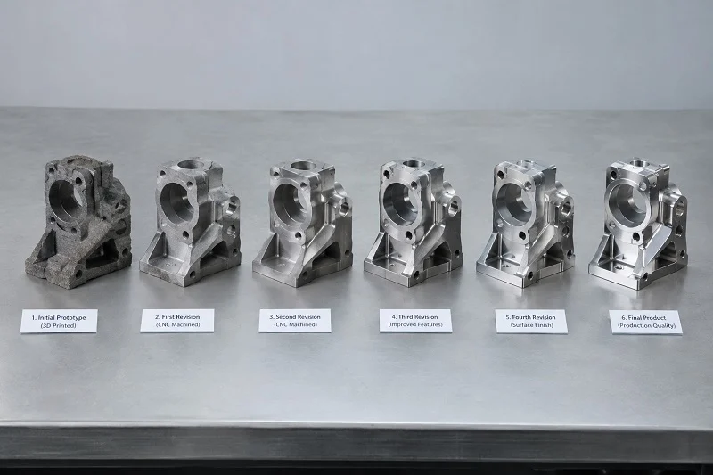
Iterative Approach
Embrace prototyping as an iterative learning process. Each prototype version provides valuable insights that inform improvements in the next iteration, ultimately leading to better final products.
Holistic Thinking
Consider prototype fabrication as part of an integrated product development strategy that includes design, validation, testing, and preparation for production. Each phase informs and optimizes the others.
Strategic Investment
View prototype fabrication not as an expense but as a strategic investment in product success. The relatively modest costs of thorough prototyping can prevent vastly more expensive problems in production or, worse, in the marketplace.
For companies ready to accelerate their hardware development, sheet metal prototype fabrication offers a proven path from concept to reality. By combining speed, precision, and flexibility, it enables innovation while managing risk—a combination that’s essential in today’s fast-moving, competitive markets.
The journey from idea to product has never been more exciting or accessible. With the right prototype fabrication partner and approach, companies of all sizes can bring their innovations to life, test them in real-world conditions, refine them based on tangible feedback, and move confidently toward successful production and market introduction.
Ready to transform your product concepts into physical reality?
The right prototype fabrication solution awaits—one that balances your specific needs for speed, quality, quantity, and budget while paving the way for successful production and market success. Your next innovation deserves nothing less than expert partnership in its journey from concept to reality.
NOBLE is a Sino-British joint venture capable of conducting independent R&D, production, and sales.
We have two major business directions: “Care Products” and “Smart Manufacturing”.
The “Care Products” business is committed to becoming a leading provider of intelligent care products and services, focusing on beauty care, health care, and elderly care. At present, we mainly sell IPL hair removal products.
We have extensive experience in sheet metal machining. We can provide full service, including design/manufacturing/assembling/inspecting & testing/packing to support your new projects. Pls feel free to contact us if you have any requirements. We are always here to serve. Please share with us the drawing, including the 3D drawing and 2D drawing.