A reagent tray’s reliability starts with the right material and ends with consistent precision. What makes reagent tray CNC machining successful? Four things work together: the right plastic or metal, a design built for manufacturability, tight machining tolerances, and strict quality checks. If you get one wrong, leaks, cracks, or costly rework follow. This step-by-step guide walks you through the whole process, from picking a substrate to final inspection. Every detail matters when chemicals and heat are involved. You will see how each choice affects performance, cost, and lead time. Ready to build trays that work well in real labs? Let us start with materials.
Materials for Reagent Tray CNC Machining
Choosing the right material is the first big choice in reagent tray CNC machining. If you get it wrong, your tray might crack, leak, or break after a few weeks in the lab. If you get it right, you save money, time, and a lot of trouble. The material affects everything: chemical resistance, heat tolerance, how easy it is to machine, and the final cost. Let’s look at the main options.
Plastics: PTFE, PEEK, Polypropylene
Plastics are common for reagent trays because they resist chemicals well and weigh very little. PTFE, PEEK, and polypropylene all belong to this group. Each one has its own good points and bad points.
Chemical Resistance & Thermal Stability
PTFE is known for its chemical resistance. It can handle almost any reagent you use, including strong acids and bases. PEEK also does well against common solvents like acetone. But PEEK is less resistant to sulfuric acid at concentrations greater than 10%, where it can be badly damaged. Polypropylene gives good all-around chemical resistance at a lower cost. For thermal stability, PEEK holds up at higher temperatures than polypropylene. PTFE also handles heat well but can change shape under heavy loads. If your lab works with strong acids, PTFE or polypropylene are safer choices. For solvent-heavy applications, PEEK works great.
Machinability and Cost Trade-Offs
Machining plastics comes with trade-offs. PTFE is soft and gummy, so it can be hard to hold tight tolerances. PEEK machines more cleanly but costs more. Polypropylene is affordable and machines reasonably well, though it can melt if speeds and feeds are too aggressive. In a practical sense, PEEK gives you the best balance of machinability and performance, but you pay for it. Polypropylene is the budget-friendly choice for less demanding jobs. PTFE sits in the middle: great chemical resistance, moderate machining difficulty, and a mid-range price.
Metals: Aluminum, Stainless Steel
Metals bring strength and durability that plastics cannot match. Aluminum and stainless steel are the two most common choices for reagent trays that need structural rigidity.
Corrosion Resistance for Harsh Reagents
Stainless steel, especially grades like 316, resists corrosion from many chemicals. It handles acids and bases better than aluminum. Aluminum, on the other hand, corrodes quickly when exposed to acidic reagents. You can coat aluminum with anodizing or other finishes to improve its resistance, but bare aluminum will not survive harsh environments. Stainless steel costs more and weighs more, but it lasts longer in tough conditions.
Weight and Durability Balancing
Aluminum is lightweight and easy to machine. That makes it great for trays that need to be moved around or used in automated systems. Stainless steel is heavier and harder to cut, but it stands up to wear and tear. If your tray stays in one place and faces aggressive chemicals, stainless steel is the better pick. If portability and weight matter more, aluminum with a protective coating works well. It is worth noting that many labs choose aluminum for general use and stainless steel for extreme conditions.
Matching Material to Application
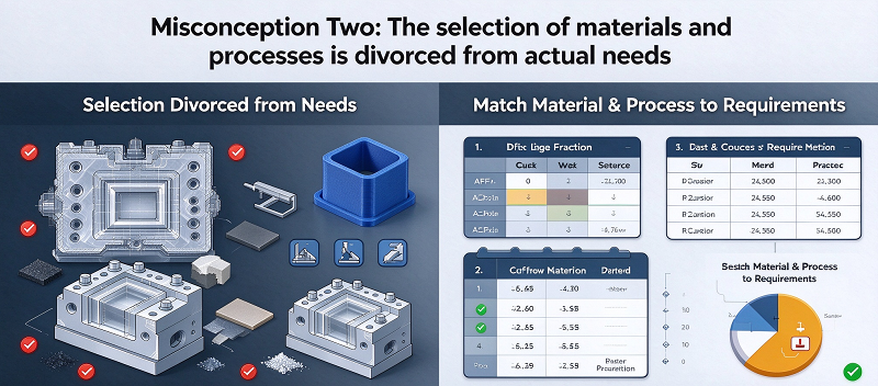
Choosing the right material comes down to your specific application. You need to think about the chemicals involved, the temperatures, the mechanical loads, and your budget.
Evaluating Chemical Compatibility Charts
Chemical compatibility charts are your best friend here. These charts list materials and their resistance to hundreds of chemicals. Look up every reagent your tray will contact. Pay attention to concentration and temperature, because both affect resistance. For example, PEEK handles acetone fine, but sulfuric acid above 10% concentration attacks it. A compatibility chart will show you these limits clearly. Always check the chart before committing to a material.
Performance vs. Budget Decisions
Budget always matters. PTFE and PEEK cost more than polypropylene. Stainless steel costs more than aluminum. But the cheapest option is not always the best. If a low-cost material fails early, you pay for replacement, downtime, and possibly damaged equipment. Proper material selection directly reduces costs and lead times. A material that lasts five years costs less over time than one that fails every six months. Work with your machining partner to weigh upfront costs against long-term performance. Companies like NOBLE, a leading manufacturer in China, offer expert guidance on material selection for prototyping and mass production. Their experience with both metals and plastics helps you avoid costly mistakes.
Design for Reagent Tray CNC Machining
Good design saves time and money. Every pocket, channel, and slot matters. The tolerances decide if the tray fits its housing. The CAD model turns your ideas into something a machine can read. Let’s walk through the key decisions.
Critical Features: Pockets, Channels, Slots
Reagent trays need pockets for holding samples. They need channels for fluid flow. And they need slots for alignment. Getting these shapes right makes the whole tray work better.
Deep Pocket Geometry & Tool Access
Deep pockets are common here. But they create real problems. Longer cutting tools bend more. That leads to tapered walls and oval holes. So you lose precision. A good rule to follow? Keep the depth under four times the tool diameter. That lets you use standard tooling. Standard tools cost less and hold better accuracy.
Internal corners matter too. A round milling cutter cannot cut a sharp corner. The corner radius matches the tool radius. So add a fillet to every inside corner. Make that fillet radius at least as large as your planned tool diameter. If you design a tiny radius, you force the shop to use a small, fragile tool. That slows the job and raises cost.
Draft Angles for Easier Release
Draft angles are less critical in CNC than in injection molding. But they still help. A slight taper on the side walls prevents burrs at the top edge. It also makes cleaning easier. Liquids drain better from a tapered pocket. That is a real advantage for lab work.
From a practical standpoint, one to two degrees of draft works well for most plastics. For metal trays, two to three degrees is safer. The angle starts at the bottom and widens toward the top. The trade-off? It takes up a tiny bit of interior space. But it improves part release from fixturing. It also simplifies cleaning thin-wall trays.
Tolerances and Fit for Lab Equipment
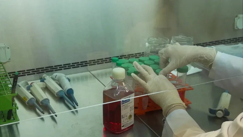
Lab equipment needs precise fits. A reagent tray must seat properly into its rack or housing. Loose fits cause wobble. Tight fits cause binding. That is why tolerances matter here.
Typical Ranges and Thermal Expansion
Standard tolerances for CNC-machined plastic parts range from a few thousandths of an inch down to very tight limits for precision work. Metal parts can hold even tighter. But cost rises as tolerances tighten. The application decides what you need.
Thermal expansion changes the game. Plastics expand much more than metals when heated. A tray machined perfectly at room temperature can bind at higher temperatures if you leave no clearance. The design should include a gap that matches the expected temperature range. That keeps the tray fitting in both cold and hot conditions.
Design for Manufacturability (DFM) Tips
DFM means thinking about production while you design. The biggest tip? Keep wall thickness uniform. Thin sections next to thick ones cool and shrink at different rates. That causes warpage. For plastic trays, a uniform wall around 0.060 to 0.125 inches works well.
Add radii to internal corners. Sharp corners create stress and slow down the tool. A radius of about 0.030 inches or larger keeps the tool moving fast. Also avoid deep, narrow slots. A slot deeper than three times its width is hard to machine cleanly. Talk to your machining partner early if you need one. They can suggest a better approach.
CAD Modeling with Fusion 360
Your design begins in CAD software. Fusion 360 is a popular choice. It gives you full control over every detail of the geometry.
Incorporating Fillets and Radii
Fillets and radii are not just for looks. They reduce stress and make machining easier. Always add a fillet at the bottom of a pocket. That removes a sharp corner where a tool cannot reach. Use the Fillet tool in Fusion 360. Set the radius to match your planned tool size.
Think about the largest tool that can reach each feature. Small radii force small tools. Small tools cut slowly. So design with the largest radius you can. For external corners, a radius protects the edge from chipping. A constant radius of about 0.060 inches for most features gives the machinist room to use a standard 1/8 inch end mill.
Simulating Machining to Avoid Collisions
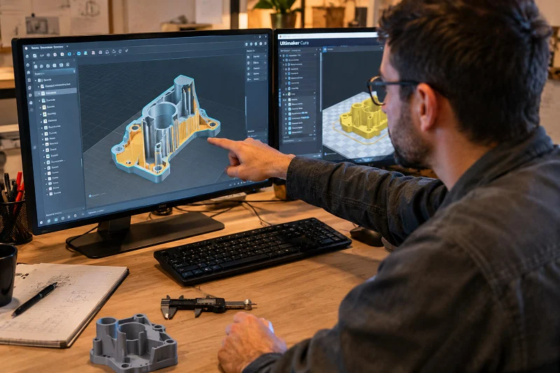
Fusion 360 has a built-in simulation tool. It shows the tool path moving through the stock. You can see if the tool hits the part or the fixture. Running a simulation before sending the file saves time. It catches mistakes like a tool holder hitting a tall wall.
Simulation also finds uncut material. You see islands where the tool could not reach. Then you can add a smaller tool operation or adjust the design. Many shops use simulation as a standard step. For reagent tray CNC machining, this is especially valuable. The parts often have multiple deep pockets and thin walls. One wrong move can ruin the part or break a tool.
Reagent Tray CNC Machining Processes
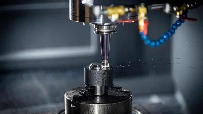
Once the design is finalized, the machining process brings it to life. In reagent tray CNC machining, three decisions dominate: the machine axis, the cutting tools, and how you hold the part. Each one ties back to the material and geometry already chosen.
3‑Axis vs. 5‑Axis Milling
Advantages for Undercuts and Angled Features
A 3‑axis mill moves the tool in X, Y, and Z. It handles flat walls and shallow pockets well. But a reagent tray often has angled channels or undercuts for snap‑fit features. Those shapes need tool tilt. With 3‑axis, you reach them by flipping the part in a vise. That adds setups and risks misalignment.
A 5‑axis mill adds two rotary axes. The tool tilts while cutting. That machines undercuts in one setup. For a tray with a 45‑degree fluid channel, the tool follows the angle directly. Surface finish stays consistent across the whole feature.
Cycle Time and Cost Implications
5‑axis often cuts cycle time by removing multiple setups. But 5‑axis machines cost more per hour. For simple trays with straight walls, 3‑axis is cheaper overall. For complex trays with angled features, 5‑axis wins on total cost per part. The break‑even point depends on your geometry.
Tool Selection for Plastic and Metal
Coatings and Geometry for Clean Cuts
Plastics and metals need different treatments. For plastic trays, use polished flute tools. The polish reduces friction and heat. No melting on the cutting edge. Uncoated carbide works for most plastics. For glass‑filled plastics, a diamond‑like carbon coating extends tool life.
For metal trays, coatings matter more. Aluminum sticks to uncoated tools. A TiB2 coating prevents buildup. Stainless steel generates high heat. An AlTiN coating handles that well. Tool geometry differs too. Plastics need higher helix angles, around 45 degrees. Metals need lower angles, around 30 degrees.
Optimal Speeds and Feeds
For plastics, run the spindle at 15,000 to 20,000 RPM. Use a chip load of 0.002 to 0.005 inches per tooth. Powdery chips mean low speed or high feed. Melted edges mean the speed is too high.
For aluminum, use 10,000 to 15,000 RPM with chip loads of 0.003 to 0.007 inches per tooth. For stainless steel, drop to 3,000 to 6,000 RPM with chip loads of 0.002 to 0.004 inches. Constant chip thickness prevents rubbing. Rubbing kills tool life fast.
Fixturing Strategies for Thin Walls
Vacuum Tables and Custom Soft Jaws
Thin walls flex under cutting forces. A vacuum table holds the part from below with even suction. For plastic trays with walls around 0.060 inches, vacuum tables are the standard.
Custom soft jaws work for second operations. You machine the jaws to match the part. They hold the tray without crushing thin sections.
Reducing Vibration and Deflection
Vibration ruins finish. Take lighter passes, around 0.010 to 0.020 inches per pass. Use a stepover of 30 to 40 percent of tool diameter.
Climb milling puts cutting force into the thick section of the wall. That reduces deflection. For very thin walls, trochoidal milling helps. The tool follows a circular path. Engagement stays constant. No sudden force spikes. The result is a clean wall with no chatter marks.
Precision Tolerances in Reagent Tray CNC Machining
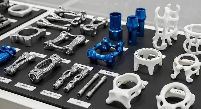
Tolerances decide whether a tray works or fails. A pocket that is too tight grips the vial. A channel that is too loose leaks. Precision tolerances in reagent tray CNC machining keep every feature within its allowed range. That range depends on the material, the feature size, and how the tray will be used. Let’s break down how shops hold those numbers steady.
Maintaining Tight Tolerances
Holding tight tolerances is not about one perfect cut. It is about controlling every variable that pushes the tool off course. Heat, wear, and vibration all move the cutting edge. A good shop watches all three.
In‑Process Probing & Tool Wear Compensation
A cutting tool wears down as it works. A worn tool cuts a smaller pocket than a fresh one. That drift adds up over hundreds of parts. In‑process probing solves this problem. The machine pauses, touches a probe to the part, and measures the actual size. Then the control adjusts the tool offset automatically. This keeps every tray within the same tolerance band from the first part to the last.
Tool wear compensation works the same way. The control tracks how long each tool has been cutting. It nudges the offset as the tool wears. For plastic trays, this matters less because the material is soft. For stainless steel trays, it matters a lot. Stainless steel wears tools quickly. Without compensation, the last trays in a batch may fall out of tolerance.
Temperature‑Controlled Environment
Heat changes everything. A shop floor that swings from cool mornings to warm afternoons will produce parts that vary in size. Metals expand when warm. Plastics expand even more. A tray machined at 68°F will not measure the same at 85°F.
Temperature‑controlled rooms keep the shop at a steady temperature. Most precision shops aim for 68°F plus or minus a couple of degrees. The machine, the part, and the measuring tools all sit in the same air. That way, measurements taken right after machining match measurements taken hours later. For trays with tight tolerances, this control is not optional. It is the foundation.
Surface Finish Requirements
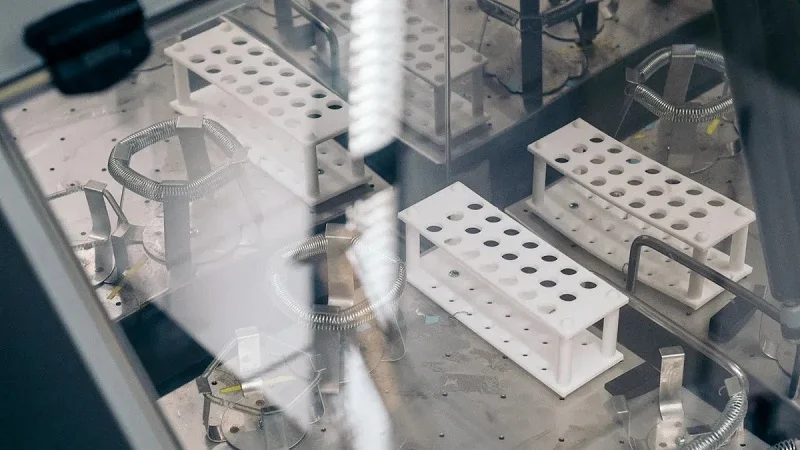
Surface finish affects how a tray performs. A rough surface traps reagent residue. A smooth surface releases it. The finish also affects how fluids flow through channels. Ra is the standard measure of surface roughness. It stands for average roughness. Lower Ra means a smoother surface.
Ra Values for Non‑Stick Surfaces
Non‑stick surfaces need a low Ra. A smooth pocket releases dried reagent better. It also cleans up faster. For plastic trays, a fine finish comes from sharp tools and light passes. The prior section mentioned passes of 0.010 to 0.020 inches. That range helps here too. Lighter passes leave a smoother wall.
For metal trays, a polished finish may be needed. That requires a different approach. The machinist uses a finishing tool with a small stepover. The stepover stays around 30 to 40 percent of the tool diameter. That keeps the scallop height low. The result is a surface that feels smooth and releases material well.
Secondary Operations When Needed
Sometimes machining alone cannot hit the required finish. Secondary operations step in. For plastic trays, vapor polishing can smooth the surface without cutting. For metal trays, bead blasting or electropolishing may be needed. Electropolishing removes a tiny layer of metal and leaves a clean, smooth surface. It also improves corrosion resistance.
These operations add cost and time. But they may be the only way to meet a strict Ra requirement. Talk to your machining partner early. They can tell you if secondary operations are needed. That way, you can plan for the extra step.
Inspection During Machining
Inspection is not just a final step. It happens during the run. Catching a problem early saves scrap and rework.
CMM and Optical Measurement Checks
A coordinate measuring machine, or CMM, uses a probe to touch the part and record its shape. It checks pocket depths, wall thickness, and hole positions. A CMM can measure features that are hard to reach with hand tools. It gives a full picture of the part’s geometry.
Optical measurement uses cameras and light. It checks surface features without touching the part. That is useful for soft plastics that might flex under a probe. Optical systems also measure many points quickly. They work well for trays with complex channels.
Statistical Process Control (SPC) Basics
SPC tracks the process over time. The shop measures a few parts from each batch. It plots the results on a chart. If the numbers drift, the operator knows something changed. Maybe the tool wore down. Maybe the temperature rose. SPC catches these shifts before parts go out of tolerance.
The basic idea is simple. You set an upper limit and a lower limit. You measure parts and plot them. As long as the points stay between the limits, the process is in control. When a point crosses a limit, you stop and fix the problem. This approach keeps quality steady across thousands of parts.
Choosing NOBLE for Reagent Tray CNC Machining

Working with the right maker brings all these parts together. NOBLE has a lot of experience in reagent tray CNC machining for labs around the world. The company works with both metal and plastic equally well. Its certifications promise the same quality for every batch. And its full-service support covers everything from design to final delivery.
Expertise in Metal and Plastic
Aluminum, Stainless, PEEK, PTFE Experience
NOBLE has proven experience machining all four of these common materials. The table below shows what they work with and where those materials are used in labs.
| Material | NOBLE’s Experience | Lab Application |
| Aluminum | CNC machining for prototyping and production runs; laser cutting and bending of aluminum sheets | Liquid handling robot parts, chassis/frames |
| Stainless Steel | CNC machining for prototyping and production runs; laser cutting and bending of stainless steel sheets | Liquid handling robot parts, complex metal manifolds with tight tolerances |
| PEEK | Covered under engineering plastics machined via CNC | Laboratory equipment / liquid handling robot parts |
| PTFE | Covered under engineering plastics machined via CNC | Laboratory equipment / liquid handling robot parts |
That range matters for reagent tray CNC machining. You get one vendor for any material. That shortens lead times and lowers errors from switching suppliers.
NOBLE’s machinists know each material’s quirks. They set speeds and feeds to avoid melting plastic or work-hardening stainless. The result is steady quality across every job.
3‑Axis and 5‑Axis In‑House Capabilities
NOBLE runs 3-axis and 5-axis CNC mills in-house. 3-axis handles simple trays with flat walls and standard pockets. 5-axis tackles angled channels and undercuts in one setup.
Using 5-axis avoids many adjustments during production. That holds tighter tolerances across complex features. You only pay for the capability your part actually needs.
Certifications: ISO 9001:2015 & ISO 13485:2016
Rigorous Quality Management System
ISO 9001:2015 governs NOBLE’s quality system. Every job follows written procedures. Parts get regular audits and fully traceable records from raw material to finished tray.
For reagent tray CNC machining, this system catches drift early. SPC charts and in-process checks keep every tray within its set range. Problems get fixed before they grow.
Medical‑Grade Process Controls
ISO 13485:2016 adds medical-grade process controls. Reagent trays often serve diagnostic equipment. This standard demands stricter oversight of every production step.
NOBLE holds both certifications. That means the same rules that govern a surgical tool also govern your tray. It is a strong sign of discipline and quality focus.
Full‑Service: Design to Assembly
DFM Engineering Support
DFM support starts before the first cut. NOBLE reviews your CAD model for manufacturability. They suggest radii or wall thickness changes that save time and money.
This early review lowers production costs noticeably. A single fillet change can eliminate a custom tool. NOBLE’s DFM team has saved clients thousands in tooling expenses.
Secondary Operations, Cleaning, Packaging
Secondary operations include anodizing, heat treatment, and surface finishing. For metal trays, anodizing adds corrosion resistance. For plastic trays, vapor polishing smooths the surface.
Cleaning removes every trace of machining residue. Packaging protects the tray during shipping. You receive a part that is ready to place in your equipment right away.
Partnering with a full-service provider like NOBLE simplifies your supply chain:
- Cost savings by avoiding tooling and equipment investments
- DFM engineering to optimize part design
- Multi-process integration under one roof
- Strict quality control throughout production
- Reduced lead times and better consistency
Four steps make reagent tray CNC machining work well. Choose the right material for your chemicals and your budget. Design with manufacturing in mind. Use precision machining with the right tools. Keep quality control strict during production. Each choice changes the final cost and how well the tray works. A smart material choice saves money. Tight tolerances keep equipment reliable. Good process control stops rework before it starts. Now you know what matters for your next project. Put these ideas to use. Reach out to NOBLE for custom solutions. Their team helps you from design through final delivery.
FAQ of for Reagent Tray CNC Machining
What material works best for a reagent tray that sees strong acids?
PTFE and polypropylene stand up well to strong acids. PEEK is not a good choice here — sulfuric acid stronger than 10% can harm it badly. Stainless steel grade 316 also fights off many harsh reagents. Before you decide, check a chemical compatibility chart for your exact chemicals, strength, and temperature.
How tight can tolerances get on a machined reagent tray?
It depends on the material and the feature. Metals hold tighter tolerances than plastics, and the cost goes up as the range gets tighter. Plastics shift more with heat, so the design needs clearance for thermal expansion. Ask your shop what your tray really needs.
Why do deep pockets cause problems in reagent tray CNC machining?
Long cutting tools bend when pushed. That creates tapered walls and oval holes. A good rule keeps pocket depth under four times the tool diameter. That lets the shop use standard tooling, which holds accuracy better and costs less. Add a fillet to every inside corner too.
Do I really need 5-axis milling for my tray?
Not always. Simple trays with flat walls and straight pockets work fine on a 3-axis mill, and that costs less per hour. Pick 5-axis when your design has angled channels or undercuts. It machines those features in one setup and holds tighter tolerances across complex shapes.
What surface finish should a reagent tray have?
A smooth surface lets dried reagent release and cleans up faster. Lower Ra values mean a smoother wall. Sharp tools and light passes get you there on plastics. Metal trays may need electropolishing or bead blasting as a second step to meet a strict Ra requirement.
How do shops keep thousands of trays identical?
In-process probing measures the part during the run and adjusts the tool offset on its own. Tool wear compensation does the same job over time. A temperature-controlled room near 68°F keeps the machine, part, and measuring tools in the same air. SPC charts catch drift before parts fall out of tolerance.
What certifications should I look for in a reagent tray CNC machining partner?
ISO 9001:2015 covers the quality management system — written procedures, audits, and traceable records. ISO 13485:2016 adds medical-grade process controls, which matters when trays serve diagnostic equipment. A supplier with both applies the same discipline to your tray as to a surgical tool.
Can one shop handle design help and finishing, or do I need multiple vendors?
A full-service partner covers DFM review, machining, secondary operations, cleaning, and packaging under one roof. That shortens lead times and cuts errors from switching suppliers. NOBLE, for example, offers DFM engineering support that has saved clients thousands in tooling expenses by catching issues before the first cut.