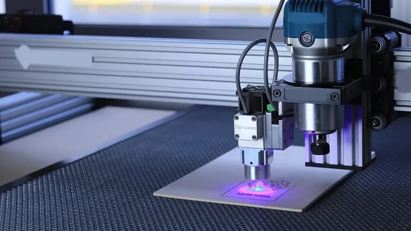
Optical platforms are the hidden heroes of modern technology. They make semiconductor lithography, aerospace imaging, and laser systems possible. These platforms are vital in high-stakes settings where precision matters most. Optical platform machining is the careful making of rigid, stable bases. These bases hold parts in perfect alignment. Even a tiny misalignment, just a micron off, can ruin system performance. In 2026, the global market is worth over $26 billion. It is growing at 11.2% each year. This guide walks you through the whole process, from picking materials to final checks. This CNC machining guide explains CNC milling, grinding, EDM, and laser cutting. We cover precision standards, material choices from metals to acrylic, and how to pick the right partner. Good techniques and materials make a big difference. This leads to dependable system performance. The right approach saves both time and money.
Overview of Optical Platform Machining
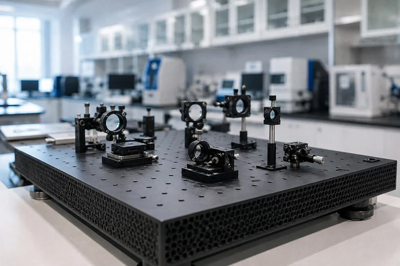
Think of an optical platform like the base of a house. Every system needs a very solid foundation. This base keeps lenses, mirrors, and sensors lined up perfectly. Without it, even the best parts cannot work together.
Defining Optical Platforms and Their Applications
What Counts as an Optical Platform
A platform is any stiff frame that holds parts in place. These parts include lenses, mirrors, lasers, and detectors. The platform must resist bending and twisting. It must also handle heat and cold without changing shape.
Common types include breadboards, tables, and mounting plates. Breadboards have threaded holes for attaching parts. Tables are bigger and heavier. They include features that reduce shaking. Mounting plates hold smaller assemblies.
The main feature is stability. The platform cannot bend under weight. It cannot change shape with temperature shifts. This stability comes from the material choice and how it is made.
Key Industries and Use Cases
Platforms show up in many high-tech fields. Semiconductor manufacturing uses them in lithography machines. These machines print tiny circuits on silicon wafers. The platform must hold the wafer steady within nanometers. Any movement ruins the chip.
Aerospace imaging systems rely on these platforms too. Satellites use them to hold cameras and telescopes. The platform must survive launch shaking. It must also work in extreme heat and cold. Laser systems also depend on stable bases. Medical lasers, cutting tools, and research lasers all need them.
Research labs use tables every day. Physicists and engineers build experiments on them. These tables test new ideas. From quantum computing to fiber optics, the platform matters. These platforms often require CNC equipment. This ensures accuracy and repeatability.
Why Precision Is Non-Negotiable
Impact of Flatness on Optical Performance
Flatness is the most important measurement. A flat surface lets light beams travel straight. If the surface is uneven, beams bend or scatter. This causes signal loss and measurement errors.
Think about a laser beam moving across a table. The beam bounces off several mirrors. Each mirror sits on the platform. If the platform is not flat, the mirrors tilt a little. The beam then misses its target. The system’s performance drops. Accuracy is lost.
Tolerances are extremely tight. Flatness must often be within 0.005 mm over 300 mm. That is about one-fifth the width of a human hair. Achieving this requires careful manufacturing control. Every step in the machining process matters. CNC machines help maintain this level of precision.
Real-World Consequences of Poor Machining
Poor machining causes real problems. In semiconductor manufacturing, a bad platform ruins wafers. Each wafer costs thousands of dollars. One misalignment wastes an entire batch.
In aerospace, a failed platform means a failed mission. Satellites cannot be fixed in orbit. The platform must work the first time perfectly. Medical laser systems also demand precision. A misaligned beam could hurt a patient.
The cost of poor machining goes beyond money. It includes lost time, damaged reputations, and safety risks. This guide helps you avoid these problems. By understanding the requirements, you can choose the right approach. The right process saves you from costly failures. This guide shows you how to get it right.
Processes Suitable for Optical Platform Machining
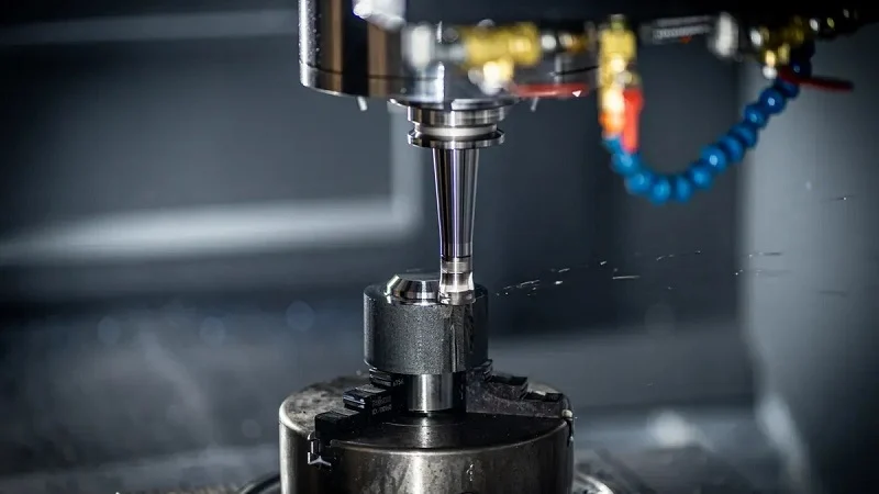
The right approach to optical platform machining follows a clear sequence. Each step removes material in a controlled way. This prevents stress buildup and ensures tight tolerances. This cnc machining guide covers the key methods you need to know.
CNC Milling Techniques
CNC milling is the main method for shaping platforms. The choice of CNC equipment depends on the part geometry and the required accuracy.
3-Axis vs. 5-Axis Machining
A 3-axis CNC machine moves along X, Y, and Z. It works well for flat surfaces and simple shapes. Most platforms have flat tops and mounting holes. A 3-axis machine handles these efficiently. It is also cost-effective.
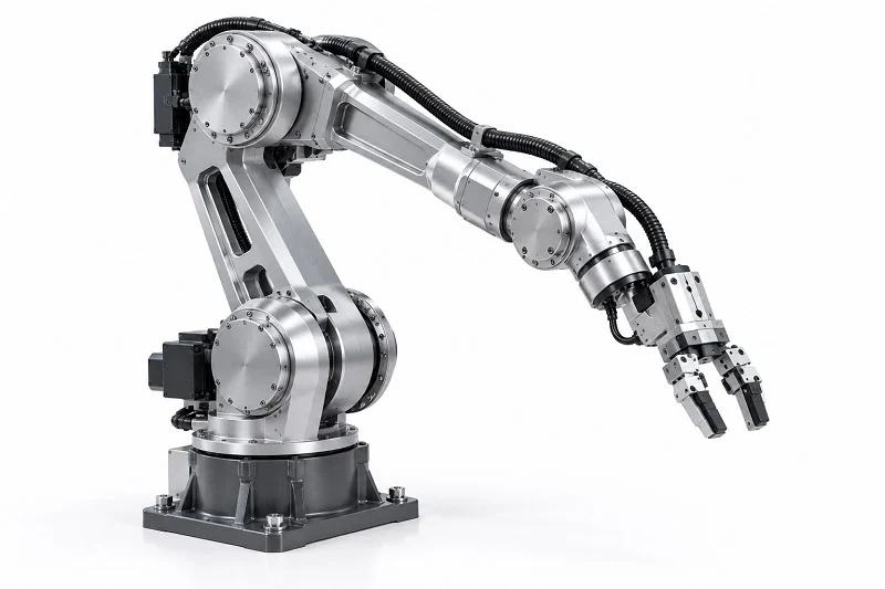
A 5-axis CNC machine adds two rotational axes. This lets the tool approach from any angle. Complex platforms with angled features benefit from 5-axis machining. It reduces errors from repositioning. For tight tolerances, 5-axis machines deliver the precision you need.
There is also 2.5-axis machining. This works for drilling and pocketing. Many platforms use 2.5-axis work for hole patterns.
Achieving Initial Geometry and Flatness
Rough machining removes most of the material. This gets the part close to the final shape. Semi-finishing uses finer tools and smaller cuts. This prepares the surface for the final pass.
The surface generation process follows a proven method. First, define the surface in CAM software using a CAD model, equation, or point cloud. Generate a rapid material removal toolpath to rough out the blank to a near-net shape. Run this on a CNC grinding machine.
Next comes rough and fine grinding. Use a ball tool to rough grind the surface, starting from the bottom and working upward. Measure the part on a metrology system and use the error map to create correction toolpaths. Repeat until the surface error is acceptable. Then switch to a finer grit ball tool and repeat the same measurement-driven correction cycle for fine grinding. This ensures accuracy in the final geometry.
This closed-loop process turns the CNC machine into a precision tool. The machine corrects its own errors based on real data. Following this cnc machining guide helps you achieve the right results.
Advanced Machining Methods
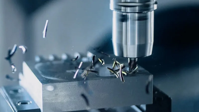
Some features require specialized processes beyond milling.
Precision CNC Grinding and Lapping
Precision grinding uses abrasive wheels to remove small amounts of material. CNC grinding machines produce very flat surfaces for machining applications. For platforms, grinding is often the final step for flatness. Lapping uses a loose abrasive between the part and a flat plate. It achieves even tighter tolerances. The process is slow but offers high accuracy.
After grinding, sub-aperture polishing follows. Polish the fine-ground surface using sub-aperture polishing techniques. Use on-board probing to calculate the removal function and guide further corrections. This refines the surface for high-quality results.
EDM and Laser Machining for Complex Features
EDM uses electrical sparks to erode material. It works well for hard metals and complex shapes. EDM creates features that milling cannot reach, such as micro-channels or deep slots with tight corners.
Laser machining uses a focused beam to cut material. It is excellent for small holes, fine patterns, and intricate features. Both EDM and laser machining are valuable additions to the cnc machining process. They handle the details that milling leaves behind.
Surface Finishing and Treatment
The final surface quality matters as much as the geometry. A rough surface scatters light and traps contaminants.
Polishing for Optical Clarity
Polishing removes the microscopic peaks left by grinding. It creates a smooth, mirror-like surface. This is critical for platforms that reflect light or sit in optical paths. The polishing process must be controlled to avoid introducing new errors. Use consistent pressure and abrasive size. Measure the surface regularly to track progress.
Coatings and Anodizing for Durability
Coatings protect the platform from wear and corrosion. Anodizing is a common treatment for aluminum. It creates a hard, non-reflective surface. This reduces stray light and improves the performance of optical equipment.
For best results, follow these guidelines:
- Refined grain structure (ASTM E112 Grade 6 or finer) to promote uniform pore development
- Surface finishing to average roughness Ra ≤ 0.4 μm for enhanced oxide uniformity
- Controlled anodizing bath chemistry for consistent oxide formation
- Avoidance of organic dyes; use clear or inorganic treatments to reduce volatile retention
- Nickel acetate sealing to mitigate humidity-driven desorption
- Post-anodization bakeout to remove retained moisture and volatiles
- Application of dense alternative coatings (sol–gel, electroless nickel, or Acktar) for elevated thermal environments
These steps ensure the coating performs well over time. The platform stays stable and reliable.
Precision Requirements for Optical Platform Machining
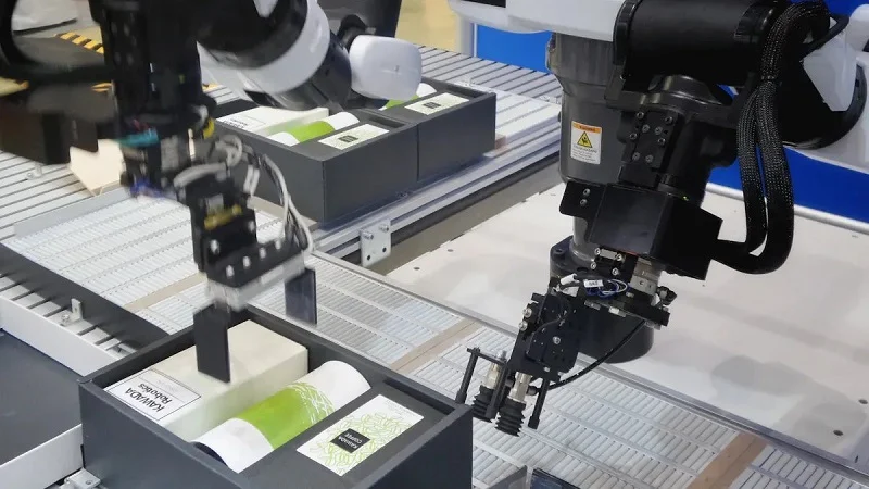
Precision is everything in making optical platforms. The numbers are very strict. A platform that looks perfect to your eyes can still fail every important test. This section explains the exact specs you need to know, how to check them, and why they matter for your final system.
Understanding Flatness and Parallelism Tolerances
Typical Tolerance Ranges
Flatness tolerances for optical platforms are in the micron range. A common spec asks for flatness within 0.005 mm over a 300 mm span. That’s about one-fifth of a human hair’s width. Parallelism between the top and bottom surfaces is often in the same range. Some high-end uses go even tighter, down to 0.002 mm.
These numbers seem impossibly small. But they are possible with the right process. The CNC machining process must have multiple passes. Rough cutting removes most of the material. Semi-finishing brings the part close to the spec. Final finishing passes get the needed flatness. Each step uses finer tools and smaller cuts. Skipping any step leads to failure.
The material matters too. Aluminum moves more during machining than steel. Invar hardly moves at all. Your tolerance goal should match your material choice. A 0.005 mm flatness spec on aluminum needs careful stress control. The same spec on Invar is easier to reach.
Measurement Techniques and Tools
You cannot trust your eyes for these measurements. You need tools that measure in microns. Coordinate measuring machines (CMM) are the main tools for this job. A CMM uses a touch probe to scan the surface. It records thousands of points and figures out flatness from the data.
Interferometry gives even higher accuracy. This method uses light waves to measure surface height. It can detect changes as small as nanometers. Interferometers are expensive and need controlled rooms. They are worth the cost for critical uses.
Surface plates and dial indicators give a simpler check. Put the platform on a granite surface plate. Move a dial indicator across the surface. This method catches big errors but is not as precise as a CMM. Use it for quick checks, not final testing.
Temperature affects every measurement. Metal expands and shrinks with heat. Measure in a temperature-controlled room at 20°C (68°F). Let the part sit and adjust before measuring. If not, your readings will be wrong.
Surface Finish Specifications
Ra, Rz, and Optical Quality Standards
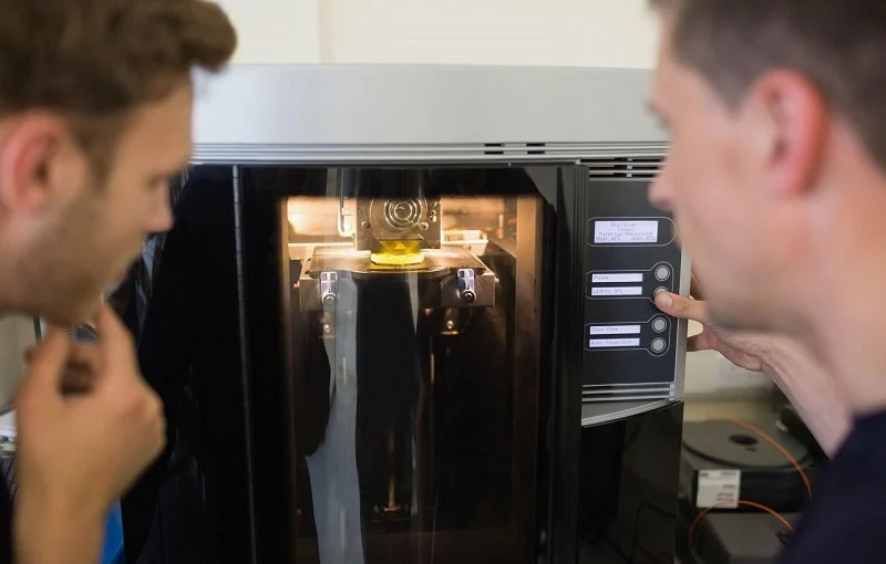
Surface finish describes the tiny texture of the material. Two main numbers are used: Ra and Rz. Ra is the average roughness across the surface. Rz measures the largest height difference between peaks and valleys. Both matter for optical platforms.
Typical Ra values for optical platforms range from 0.4 to 0.8 micrometers. Polished surfaces can reach 0.1 micrometers or better. Rz values are usually four to six times higher than Ra. The ratio depends on the machining process used.
Optical quality standards go beyond simple roughness. They also consider waviness, scratches, and digs. A surface can have good Ra but still scatter light because of waviness. Full optical quality certification needs interferometric testing. This checks that the surface meets the full spec, not just one number.
How Finish Affects System Performance
Surface finish directly affects how the system works. Rough surfaces scatter light. This causes stray light in the optical path. Stray light lowers contrast and creates noise in measurements. In laser systems, rough surfaces can cause unwanted diffraction patterns.
Finish also affects how long the platform lasts over time. Rough surfaces trap dirt and dust. They are harder to clean. They provide more area for corrosion to start. A smooth surface avoids these problems.
The finish requirement should match the use. A platform holding a mirror needs a better finish than one holding a detector. Think about where the platform sits in the optical path. Parts near the light source need the finest finishes. Parts further away can handle slightly rougher surfaces.
Dimensional Stability and Thermal Management
Material Selection for Thermal Stability
Every material expands when heated. The coefficient of thermal expansion (CTE) tells you how much. Aluminum has a CTE around 23 ppm/°C. Steel runs about 12 ppm/°C. Invar, a nickel-iron alloy, drops to about 1.2 ppm/°C.
The choice depends on your operating environment. A lab with stable temperatures can use aluminum. Aerospace uses face wide temperature changes. They need Invar or similar low-expansion materials. The platform must hold alignment across the whole temperature range.
Matching materials matters too. If the platform and the optical parts have different CTEs, they expand at different rates. This creates stress and misalignment. Choose materials with similar CTEs for important assemblies.
Stress Relief and Aging Processes
Machining puts internal stress into the material. Cutting tools push and pull the metal. This leaves locked-in stress inside. Over time, that stress lets go. The part warps. Flatness is lost.
Stress relief processes stop this problem. Heat treatment cycles the material to relax internal stresses. The part is heated slowly, held at temperature, then cooled slowly. This process can take hours or days. It is needed for precision parts.
Natural aging is another option. The part sits for weeks or months after rough machining. Stress releases slowly. Then the part gets its final machining pass. This method costs time but keeps accuracy.
Some shops use cryogenic treatment. The part is cooled to very low temperatures. This stabilizes the material structure. It works well for steels and other metals. The process adds cost but improves long-term stability.
The best approach combines stress relief with careful machining. Rough machine the part. Stress-relieve it. Then do the final finishing passes. This order locks in the geometry. The part stays flat for years, not just weeks.
Every step in this process needs discipline. The CNC machining guide principles apply throughout. Measure, correct, and measure again. This closed-loop approach gives the precision your optical system needs. The effort pays off in reliable performance and fewer field failures.
Key Design Considerations for Optical Platform Machining
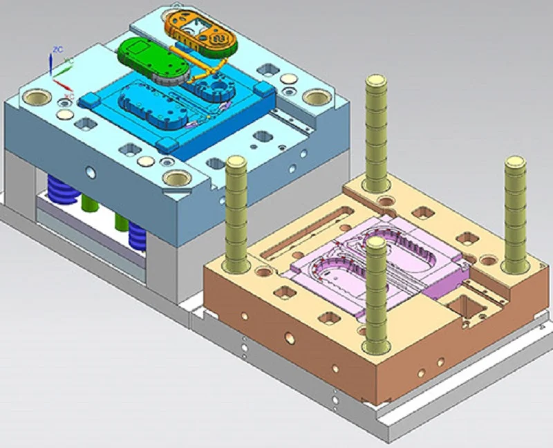
Good design is very important. Your early choices affect cost, accuracy, and how long the platform stays stable. This section explains the key decisions for optical platform machining.
Material Selection for Optical Platforms
Aluminum, Steel, and Invar
Aluminum is the most common choice. It is light, easy to cut, and cheap. Alloy 6061-T6 is easy to machine. Alloy 7075-T6 is stronger. Both work well for most platforms.
Steel is stiffer and dampens vibrations better. It costs more and weighs more. Steel works well for large platforms that need extra strength.
Invar is the top choice. It barely expands with heat, so it stays stable as temperature changes. Aerospace and measurement tools often use Invar. It costs more and takes longer to machine.
The right material depends on where you use it. A lab with steady temperature can use aluminum. A satellite that faces extreme heat and cold needs Invar. Each CNC material has its own pros and cons.
Acrylic CNC Machining for Prototyping
Acrylic is a smart choice for early testing. This clear plastic is easy to cut and cheap to buy. Acrylic CNC machining lets you test hole patterns and part layouts before you switch to metal.
The downside is thermal stability. Acrylic expands more than metal. It cannot hold tight tolerances when temperature changes. But for proof-of-concept work, acrylic is great.
Machining acrylic is similar to metal. It uses sharper tools and slower speeds. Heat can melt the plastic, so cooling is important. Design tips for acrylic CNC include avoiding sharp inside corners and keeping wall thickness even.
Acrylic CNC machining works well for small runs. Quantities from 10 to 1000 units are cost-effective. You can test your design before spending on metal production. Acrylic also lets you see inside your assembly. This helps you spot alignment issues early. Machining acrylic is faster than metal, so your development cycle is shorter.
Structural Design for Rigidity
Ribbing and Honeycomb Structures
Flat plates bend when weight is put on them. Adding ribs underneath makes them stiffer without adding much weight. Ribs run across the direction of bending. They stop flexing and keep the surface flat.
Honeycomb structures are even stiffer for their weight. Two thin face sheets hold a honeycomb core in between. This design resists bending in all directions. It works well for large platforms where weight is important.
Machining must handle these features carefully. Deep cavities and undercuts cause tool bending. This hurts accuracy. Keep features easy to reach with standard tools. Uniform wall thickness stops warping during machining.
Vibration Damping Features
Vibration ruins optical measurements. The platform must absorb energy instead of passing it along. Material choice helps. Cast iron and steel dampen vibrations naturally. Aluminum passes them through.
Add damping features to your design. Fill hollow sections with damping material. Use constrained-layer damping, where a viscoelastic sheet sits between two metal layers. These features reduce chatter during machining and vibration during use.
Mounting and Alignment Features
Precision Holes and Slot Placement
Mounting holes hold optical parts in place. Their position matters as much as their size. Hole patterns must match the parts they hold. Slot placement lets you adjust during assembly.
Tolerances for these features are usually ±0.01 mm to ±0.05 mm. Surface roughness is between Ra 0.4 μm and Ra 1.6 μm. These numbers need careful control of cutting forces and tool deflection.
For parts that are not very stiff, size tolerances are usually from ±0.01 mm to ±0.05 mm, and surface roughness is often between Ra 0.4 μm and Ra 1.6 μm. Reaching these numbers needs careful control of cutting forces, temperature changes, and tool bending.
Kinematic Mounts and Reference Surfaces
Kinematic mounts let you put parts in the same spot over and over. They use three contact points to set a unique position. This design avoids too much constraint and ensures the same alignment every time.
Reference surfaces give machinists a steady starting point. These flat, machined areas are used as markers for measurement. They must be machined first and kept safe during later steps.
| Design Factor | Impact on Rigidity | Impact on Cost-Effectiveness |
| Machine stiffness | Reduces shaking and bending | Cuts waste and redo work |
| Tooling selection | Reduces tool bending | Makes tools last longer |
| Workholding | Keeps part steady | Prevents mistakes |
| Tolerance specification | Focuses effort on key surfaces | Lowers costs by 15-30% |
| Design for manufacturing | Keeps structure strong | Makes machining simpler |
This CNC machining guide highlights planning. Every design choice affects the final result. Focus on making it easy to machine. Avoid deep cavities. Set tolerances that match what your machines can do. These steps keep costs down while keeping precision. The right design choices also improve the precision of your final assembly. And they boost overall system performance.
Common Challenges in Optical Platform Machining
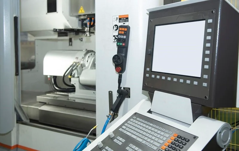
Every machining project has obstacles. From acrylic prototypes to metal production runs, each material brings its own challenges. Heat causes expansion. Vibration leaves marks. Residual stress makes parts warp. Getting it right starts with understanding these challenges. This cnc machining guide covers the most common issues and their solutions.
Managing Thermal Expansion
Heat is a hidden enemy. When metal heats up, it expands. Different materials expand at different rates. This creates misalignment.
Material Matching and Compensation
Choose materials with similar expansion rates. Invar barely moves with temperature changes. Metal matrix composites like AlSiC offer controlled expansion. This eliminates the need for mechanical compensation. The CTE matches device requirements. AlSiC is lightweight. It weighs one-third less than traditional alloys. High stiffness improves alignment. For prototyping, acrylic cnc machining offers a quick way to test designs. But acrylic expands more than metal. Acrylic works well for early testing.
Temperature-Controlled Environments
Temperature control starts with the shop environment. Keep the floor at 20°C (68°F). Let parts stabilize before cutting. Active cooling systems remove heat from the cutting zone. Compensation algorithms adjust cnc machining parameters in real time. This maintains precision during long operations. After startup, accuracy can drift for 30 minutes. This causes base warping. Running a warm-up cycle helps. So does monitoring temperature throughout the process.
Minimizing Vibration and Chatter
Vibration leaves marks on the surface. It ruins flatness. Optical performance suffers when vibration is not controlled. The cnc machine must be set up correctly.
Tool Selection and Spindle Optimization
Tool geometry matters. A stiff tool resists bending. A sharp tool cuts cleanly. Spindle speed affects vibration too. Find the right balance. The right combination of machine rigidity, tool geometry, and cutting parameters controls vibration. This guide covers the basics. Apply them to every cnc setup. Every cnc machining step needs careful planning.
Fixturing and Damping Strategies
How you hold the part matters. A loose fixture lets the part move. A rigid fixture keeps it steady. External sources create low-frequency ground vibrations. These micron-level vibrations ruin nano-scale cnc machining results. Self-excited vibration comes from the cnc machine itself. Use vibration-isolation pads. Add damping material to the platform design. An integrated approach combines thermal compensation with vibration damping. This ensures consistent precision throughout the machining process.
Preventing Material Deformation
Material moves during cutting. Internal stresses are released. The part warps. The cnc machining process must account for these forces.
Stress Relief Before and After Machining
Start with stress-relieved materials. O-temper materials have less internal stress. Multiple stress-relief cycles between roughing and finishing passes help. Each cycle relaxes the metal. Internal stresses reach equilibrium before final dimensions are cut. This prevents warp after cutting. The process takes time but pays off. For acrylic, stress relief is simpler. Annealing the plastic before machining reduces internal stress. Accuracy improves with each cycle. Precision depends on proper stress relief.
Proper Clamping Techniques
Clamping force can cause problems. Traditional clamps apply localized pressure. The part springs back after release. Potting techniques solve this problem. Fill cavities with rigid wax or low-melting-point alloy. This provides temporary stiffness. It distributes support evenly. Spring-back deformation is prevented. The part stays flat after the clamps come off. It adds a step to the cnc machining process.
Best Practices for Optical Platform Machining
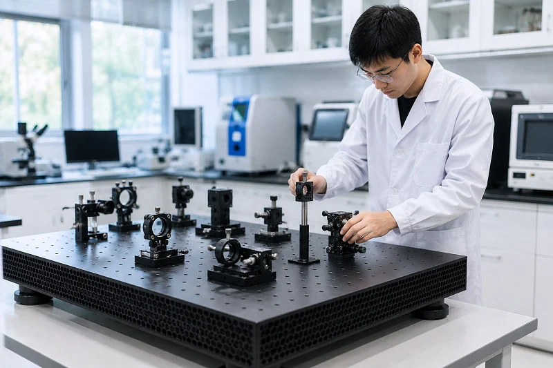
Getting optical platform machining right needs more than good tools. You need the right partner, careful checks, and smart spending. These practices help you avoid costly mistakes.
Partnering with Experienced Machinists
Your machining partner affects your success. A shop that knows optical work finds problems before they cost you money. They also give design feedback to make parts easier to make. Ask for DFM input early, not after you finish drawings.
Questions to Ask Your Machining Partner
Before you commit, ask specific questions about what they can do:
- Thermal Management Strategy: Ask about cooling methods like high-pressure air blasts or vaporized oil mist. A good shop shows how they stop heat from causing smearing and internal stress.
- Tooling and Cutting Geometry: Check if they use tools made for plastics—positive rake angles, polished flutes, diamond tooling. Regular metal-cutting tools can mean problems.
- Fixturing and Clamping Methods: Ask how they hold your part. Vacuum tables, double-sided tape, or soft jaws spread out pressure and stop stress cracks.
- Post-Processing Capabilities: Check that they do polishing and buffing in-house. Outsourcing can lead to uneven results.
- Quality Control and Certifications: Ask about CMM machines and certifications like ISO 9001 or ISO 13485. These check that tolerances are as tight as ±0.01 mm.
A partner like NOBLE, a top Chinese manufacturer, offers great service and expert knowledge. They help clients go from prototyping to mass production smoothly. Their engineers work with you on design improvements before machining starts.
Prototyping vs. Production Runs
Prototyping and production need different methods. For prototypes, acrylic is fast and cheap. Acrylic CNC machining lets you test hole patterns and alignment fast. You find design problems before you spend on metal.
Production runs need tighter control. The cnc machining process must be repeatable. Tool wear, temperature changes, and material differences all affect results. Your partner should record every step. They should also track how many parts pass inspection.
Quality Control and Inspection Protocols
A careful quality process protects your money. It starts with checking the raw material and ends with final size checks. Every step matters for optical specs.
In-Process Inspection Methods
Checks during machining catch problems early. First Article Inspection checks all critical dimensions before full production. This uses a CMM that is calibrated to ISO 10360. Regular sampling during the run checks tolerances like true position and flatness. Mid-production surface roughness checks use portable profilometers. These confirm the surface texture before final finishing.
Final Verification and Documentation
Final inspection leaves nothing to chance. A 100% check of critical features on a CMM creates color-coded maps of errors. Lab-grade profilometers scan the whole optical surface. They measure peak-to-valley roughness and waviness. Senior inspectors look for tiny scratches and dirt before ultrasonic cleaning.
Documentation is also important. You need to trace every part. Certificates of conformance, inspection reports, and material certifications protect you later.
Balancing Cost, Time, and Quality
Every project balances three limits. Smart choices keep quality high without spending too much.
Where to Invest vs. Where to Save
Spend money on material quality and stress relief. These stop failures later. Save on features that are not critical. Loose tolerances on mounting holes cut machining time. This cnc machining guide says to focus precision where optics need it. Acrylic prototypes save money early. Metal production is worth higher spending.
Lead Time Considerations for Complex Parts
Complex platforms take time. Stress relief cycles alone can add days. Plan for many machining passes. Each pass removes less material but makes the part more accurate. Rushed timelines force shortcuts. Shortcuts hurt precision. Add extra time to your schedule. Tell your partner about lead time needs early. A good partner helps you plan operations well.
The right process balances all three factors. Measure, record, and adjust. This approach gives you platforms that work well for years.
Partnering with NOBLE for Optical Platform Machining
Picking the right manufacturing partner makes a huge difference. NOBLE focuses on metal and plastic processing. We provide a complete range of services from design to assembly. That means you work with one team from beginning to end. No juggling multiple vendors. No lost information between shops. Just one accountable partner for your optical platform machining needs.
Our Manufacturing Capabilities
Full-Service from Design to Assembly
Most shops just cut parts. NOBLE goes further. Our engineers review your design before we touch any material. We spot potential problems early. We suggest changes that make parts easier to make. This design-for-manufacturability approach saves you time and money.
Our services cover the entire production cycle. We handle material sourcing, machining, surface treatment, and assembly. You get finished assemblies ready for integration. This full-service model reduces your supply chain risk. It also shortens your time to market. For complex optical platforms, having one partner simplifies everything.
Advanced CNC and Finishing Equipment
Our facility runs advanced CNC machines. We have 3-axis and 5-axis mills for complex geometries. We also operate precision grinding equipment for tight flatness requirements. This equipment handles everything from rough cutting to final finishing passes.
We work with many materials. Aluminum, steel, and Invar are common choices. We also machine acrylic for prototyping work. Acrylic CNC machining lets you test designs quickly and cheaply. Our finishing capabilities include anodizing, polishing, and coating application. Every step follows strict quality procedures.
Certifications and Quality Assurance
ISO 9001:2015 Certified Processes
Quality is not a promise. It is a system. NOBLE holds ISO 9001:2015 certification. This international standard covers every part of our operations. It ensures consistent quality across all projects. Our quality management system tracks every step of the machining process. We document everything. We measure everything. We improve continuously.
This certification means you get the same quality every time. Whether you order one prototype or a thousand production units, the process stays the same. That consistency matters for optical platform machining. Your systems depend on repeatable results.
ISO 13485:2016 for Precision Applications
We also hold ISO 13485:2016 certification. This standard applies to medical device manufacturing. It demands even stricter controls than ISO 9001. This certification shows our commitment to precision. It proves we can handle applications where failure is not an option.
Medical lasers, diagnostic equipment, and surgical systems all rely on optical platforms. These applications need the highest level of quality assurance. Our ISO 13485 certification gives you confidence. You know your parts meet the most demanding standards.
Why Choose NOBLE for Your Optical Platforms
Engineering Collaboration and DFM Support
We do not just take orders. We partner with your engineers. Our team provides design-for-manufacturability feedback early in the design phase. We help you optimize your design for cost and performance. This collaboration prevents expensive mistakes later.
For example, we might suggest changing a deep pocket to a shallower feature. This small change could reduce machining time significantly. Or we might recommend a different material that meets your specs at a lower cost. These insights come from years of experience. They save you money on every project.
Commitment to Precision and Reliability
Precision is our foundation. Every optical platform machining project gets the same attention to detail. We use calibrated equipment and trained operators. We inspect parts at multiple stages. We provide full documentation with every shipment.
Our commitment extends beyond individual parts. We build long-term relationships with our clients. We understand your products and your quality requirements. This understanding lets us deliver better results over time. When you need a partner who can grow with you, NOBLE delivers.
This guide has covered materials, processes, and best practices. The final piece is choosing the right partner. With NOBLE, you get technical expertise, certified quality, and genuine collaboration. That combination turns good designs into reliable optical systems.
This cnc machining guide covered materials and processes. Optical platform machining requires deep knowledge. The 2026 landscape demands tighter machining tolerances and new techniques. Acrylic cnc machining uses acrylic. Acrylic is easy to cut. Acrylic works for early stages. Acrylic saves money on development. Precision machining and quality control stay constant. Cnc machining needs careful planning for good performance. The right cnc setup and each cnc step require attention. Modern cnc equipment and skilled cnc operators deliver quality results. Precision cnc work and reliable cnc machining ensure success. The cnc process requires discipline. This process defines success. Proper machining and fine machining yield results. Consistent machining builds trust. For complex projects, partner with NOBLE for full-service support. The future of platform machining needs a partner who grows with you.
FAQs of Optical Platform Machining
What flatness level should a good optical platform have?
Most specs ask for 0.005 mm over 300 mm. For high-end uses, it goes down to 0.002 mm. The right CNC setup and material choice help you hit these numbers every time.
How does the material choice affect how the platform works?
Aluminum is light and cheap. Steel adds stiffness. Invar barely changes size with heat. For prototypes, acrylic CNC machining gives you a fast, cheap way to test designs. Acrylic saves time and money.
Is acrylic a good choice for testing optical platforms?
Yes. Acrylic CNC machining is fast and saves money. You can test hole patterns and alignment quickly. Just remember that acrylic expands more than metal. Acrylic works for proof-of-concept, not for final products. Use acrylic to check your design.
What machining process works best for optical platforms?
CNC milling handles most shapes. Precision grinding and lapping give very flat surfaces. EDM and laser cutting create complex features. Each CNC step builds on the last. The right order matters.
How do you handle thermal expansion during cutting?
Keep your shop temperature at 20°C. Let parts rest before cutting. Use active cooling systems. For acrylic CNC machining, use low speeds to avoid melting. The right CNC setup stops heat-related errors. Acrylic needs extra care.
What causes warping in optical platform parts?
Internal stress from cutting releases over time. The part changes shape. Stress relief cycles between rough and finish passes prevent this. Proper clamping helps too. Acrylic parts can warp from heat buildup during CNC machining.
What certifications matter when choosing a machining partner?
ISO 9001:2015 covers general quality. ISO 13485:2016 applies to medical and precision work. These certifications show that a shop follows strict processes. For optical platform work, they matter a lot. Acrylic CNC machining needs the same quality standards.
How do you balance cost and precision for optical platforms?
Spend money on material quality and stress relief. Save on features that are not critical. Use acrylic CNC machining for prototypes. Move to metal for production. Acrylic helps you test without high costs. A good CNC partner helps you find the right balance.