A medical optical housing protects delicate parts in life-saving medical devices. Failure is not an option here. A tiny misalignment can ruin an entire diagnostic procedure. Choosing materials and manufacturing processes are connected decisions. You must make them together, not one after the other.
So how do you balance optical alignment, biocompatibility, sterilization resistance, and cost? That’s the main challenge for any medical device housing project. This post gives you a step-by-step plan. The plan starts with functional requirements. No extra details, just useful advice for your next medical technology project. Let’s get right to the decision-making challenge.
Functional Requirements for Medical Optical Housing
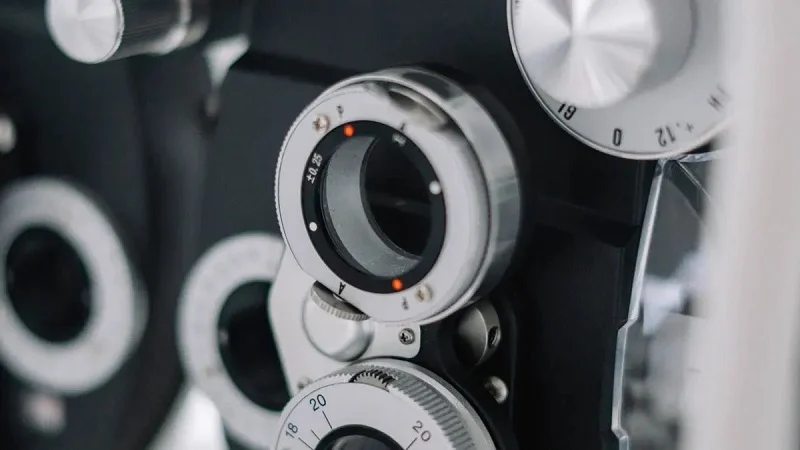
First, you must define what the housing needs to do. If you skip this step, you are just guessing. Every later choice about materials and processes depends on what you write here. So let’s look at the three key areas you must decide before anything else.
Optical Alignment and Dimensional Stability
Your optical path depends on dimensional stability. Even a small warp moves the focal point. That shift ruins image quality. So you need to think carefully about how your housing performs in real-world conditions.
Tolerance Requirements and CTE Mismatch
Tight tolerances matter, but they only show part of the picture. The real challenge is coefficient of thermal expansion (CTE) mismatch. Glass lenses expand slowly. Metal housings expand faster. When temperatures change, that mismatch creates stress at mounting points. The result? Optical axis shifts of several micrometers per degree Celsius. In endoscopic imaging systems, that means noticeable focus drift.
| Component | CTE (µm/m·K) | Impact on Alignment | Mitigation Strategy |
| Silica core (fiber) | 0.55 | Minimal expansion but high mismatch with jacket | Use low-CTE polymer or compensating metal braid |
| Polymer jacket | 70 | Large expansion causes stress and micro-cracks | Add expansion joint at connector interface |
| Stainless-steel housing | ~17 | Mismatch with bundle leads to differential expansion | Size expansion joint using ΔL = α·L·ΔT, for 0.5m bundle and 40°C range, ΔL ≈ 15mm |
That 15mm expansion example shows why you can’t ignore CTE. A steel housing with fiber optics needs room to expand. Otherwise, the optical path bends and shifts.
Mounting Features and Stress Relaxation
Your mounting features hold everything in place. But over time, plastics relax. Screws loosen. Snap-fits creep. This stress relaxation changes the forces on your optical parts. The alignment drifts slowly. You might not notice it in a week, but after a year of use, the image quality drops noticeably. Design your mounts with this in mind. Add retention features that keep force over time.
Sterilization and Chemical Resistance
Medical devices face harsh cleaning cycles. Your housing must survive them without breaking down. This need often rules out otherwise attractive materials.
Autoclave, EtO, and Gamma Compatibility
Sterilization methods vary widely. Autoclave cycles push temperatures above 120°C with steam. EtO gas penetrates but leaves residues. Gamma radiation breaks polymer chains over time. Each method stresses your materials differently. Polycarbonate handles gamma reasonably well but struggles with repeated autoclaving. Metals handle all three but add weight and cost. Your choice depends on which sterilization method your device will actually face.
Disinfectant and Cleaning Agent Exposure
Daily cleaning between sterilization cycles matters just as much. Common hospital disinfectants can attack your housing materials:
- Quaternary ammonium compounds
- Sodium hypochlorite (bleach)
- Hydrogen peroxide
- Ethanol (ethyl or isopropyl alcohol)
These agents cause stress cracking in polycarbonate and ABS housings. The cracks start small, then spread under load. Your material selection must account for chemical compatibility with every cleaning product your device might encounter.
Mechanical Durability and Impact Resistance
Medical devices drop. They get knocked around. Your housing needs to protect the optics inside through all of it.
Drop Testing and Vibration Tolerance
Drop testing from counter height is standard for handheld diagnostic equipment and requires precision. The housing must absorb impact without transferring energy to the optical assembly. Vibration tolerance matters too, especially for devices mounted on carts or equipment racks. Resonant frequencies can amplify small vibrations into alignment-killing oscillations.
Long-Term Creep and Fatigue Performance
Creep happens slowly. A housing that looks fine after a week might deform after a year of constant load. Fatigue cracks appear after thousands of stress cycles. For surgical instruments and implantable devices, these long-term properties are non-negotiable. You need materials with proven track records in similar applications. Don’t rely on short-term testing alone.
These functional requirements form your foundation. Once you define them clearly, you can evaluate materials and manufacturing processes with confidence. That’s where we head next.
Evaluating Materials for Medical Optical Housing
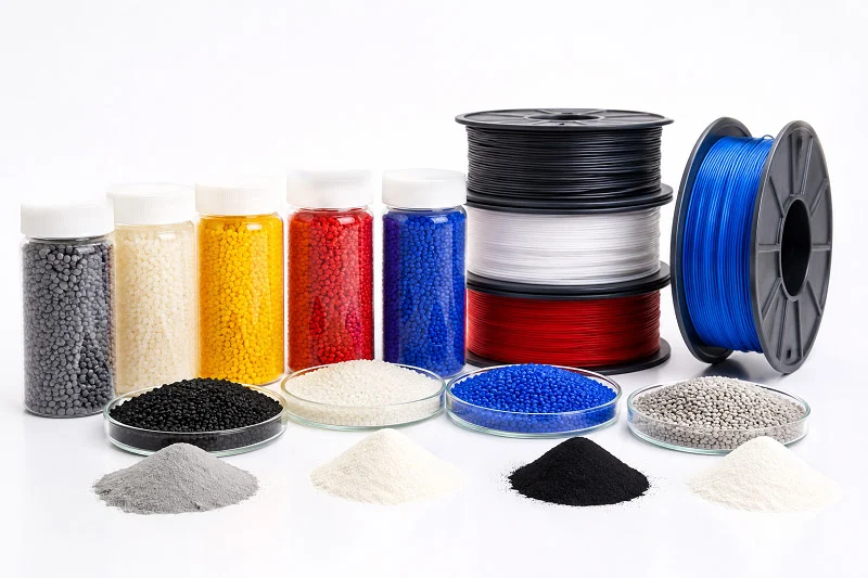
Now we get to the core issue. The material you pick affects everything that comes next. The right material must pass four checks: biocompatibility, functionality, durability, and safety. Use these as your filter. If a material fails any one of them, it’s out. No exceptions.
Engineering Plastics: PC, ABS, and PC/ABS Blends
Engineering plastics are the top choice for medical device housings. They are light, easy to shape, and cheap to make in large numbers. But they are not the same. Each one brings different traits to the table.
Optical Clarity and Light Transmission Properties
Polycarbonate is the best when you need to see through your housing. It lets 88–90% of visible light pass through, nearly as clear as glass. That makes it the top pick for clear windows, lens covers, and sight glasses in diagnostic tools.
ABS, on the other hand, is naturally opaque. You cannot see through it, and you should not try. Its strength lies in toughness and impact resistance, not optical performance.
PC/ABS blends sit in a tricky middle ground. The refractive index mismatch between the polycarbonate phase (1.585) and the ABS phase (1.54) causes light to scatter at every phase boundary. This scattering blocks true optical clarity. Translucent grades exist, but they only work for indicator light covers or backlighting diffusers. If you need 87–89% light transmission, PC/ABS physically cannot deliver it.
| Material | Light Transmission | Optical Classification |
| Polycarbonate (PC) | 88–90% | Water-clear, approaching glass clarity |
| ABS | Not specified | Opaque |
| PC/ABS Blend | Limited translucency only | Inherently opaque due to refractive index mismatch |
Biocompatibility and USP Class VI Compliance
Biocompatibility is not optional. It is a regulatory gate. USP Class VI testing covers systemic toxicity, intracutaneous irritation, and implantation. Passing these tests means your material will not harm living tissue.
Polycarbonate and ABS/PC-ABS blends appear on the list of thermoplastics commonly used for medical device housings, diagnostic equipment casings, and non-patient-contact components. That is good news for most projects. But remember: biocompatibility applies to the final part, not just the raw resin. Additives, colorants, and mold release agents can change the picture. Verify your complete formulation, not just the base polymer.
High-Performance Metals: Aluminum and Stainless Steel
Plastics cannot handle every job. When heat builds up, or electromagnetic interference threatens your optics, metals step in.
Thermal Management and EMI Shielding Benefits
Aluminum conducts heat far better than any plastic. If your optical assembly generates heat, a metal housing acts as a heat sink. It pulls thermal energy away from sensitive components and keeps the optical path stable.
Metals also block electromagnetic interference. Plastic housings let EMI pass through, which can corrupt signals from optical sensors. Aluminum and stainless steel create a Faraday cage effect, shielding your electronics from external noise. For devices near MRI machines or surgical instruments that use electrosurgery, this shielding is critical.
Surface Finishing and Anodization Options
Aluminum offers excellent surface finishing options. Anodization creates a hard, corrosion-resistant layer that also accepts dyes. You can match brand colors or use dark finishes to reduce internal reflections. Stainless steel does not anodize, but it polishes to a mirror finish or bead-blasts to a matte texture. Both metals handle repeated sterilization cycles without degrading.
Specialty Polymers: PMMA, ASA+PC, and LCP
Sometimes standard plastics and metals do not fit the bill. Specialty polymers fill those gaps with tailored properties.
Weatherability and UV Resistance
PMMA, better known as acrylic, offers outstanding UV resistance. It will not yellow or become brittle after years of light exposure. ASA+PC blends combine ASA’s weatherability with polycarbonate’s impact strength. These materials suit devices that sit near windows or under bright surgical lights. Standard PC would degrade under the same conditions.
High-Temperature Performance and Flow Characteristics
LCP, or liquid crystal polymer, handles extreme temperatures that melt other plastics. It also flows exceptionally well in thin-wall molds, filling complex geometries that trap other resins. For miniaturized optical housings with intricate internal channels, LCP’s flow properties make it invaluable. The trade-off? Higher cost and limited color options.
Do not forget TPE and TPU. These elastomers serve as gasketing or overmolding materials within your housing assembly. They create soft-touch grips, seal against moisture, and absorb vibration. They are not structural materials, but they complete the assembly.
One more thing: material selection is a long-term decision. You cannot easily swap resins after tooling is cut. Every material must also work with your chosen manufacturing process. Injection molding, CNC machining, and 3D printing each have their own material compatibility lists. Check that your shortlisted materials actually work with your production method before committing.
The properties you choose today will determine your device’s performance for years. Whether you are building for surgical instruments, implantable devices, or dental implants, the same logic applies. Test thoroughly, verify biocompatibility, and confirm sterilization compatibility early. Your future self will thank you.
Matching Materials to Manufacturing Processes
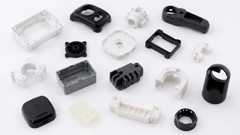
Your material list is ready. Now comes the next big question: how will you make the parts? The manufacturing method you pick shapes everything—cost, lead time, quality, and even which materials you can use. Production volume, tolerance requirements, and material properties drive this decision. Let’s walk through the three main options.
Injection Molding for High-Volume Production
When you need thousands of identical parts, injection molding is the workhorse. It delivers consistent quality at scale, and the per-part cost drops dramatically as volume rises.
Achieving Tight Tolerances and Repeatability
Injection molding of optical components can achieve repeatable part tolerances of 0.500 mm, and in some cases up to 0.125 mm. That level of precision suits medical device housing applications where alignment matters. The process also offers high repeatability, allowing thousands of identical parts from a single mold.
Precision injection molding takes this further. Critical features can hold tolerances down to ±5 microns. How? Scientific molding techniques make the difference. Velocity profiling controls how fast the resin fills the cavity. Cavity pressure monitoring ensures consistent packing. Gate freeze validation confirms the part solidifies correctly every cycle. These methods apply directly to optical surfaces in medical devices—think lenses or guides in optical-based diagnostic sensors. Diagnostic equipment requires precision at every level, and these techniques deliver it.
The benefits are clear: optical clarity, consistent quality, and reduced rework. For regulated medical devices, that consistency is gold. These injection-molded casings meet strict dimensional requirements while keeping production costs manageable.
Mold Design for Optical Surfaces and Gating
The mold itself deserves careful attention. Gate placement determines how the resin flows across optical surfaces. Poor gating creates weld lines or flow marks that distort light transmission. For clear polycarbonate windows, you want the gate positioned so the flow front moves smoothly across the viewing area.
Wall thickness transitions matter too. Abrupt changes create sink marks and internal stress. Rib structures help maintain stiffness without adding thick sections. But ribs must be sized correctly—too thin, and they don’t support; too thick, and they cause sink marks on the opposite surface. Injection molding must be controlled at every step, from melt temperature to cooling rate, to prevent warpage. These precision components demand that level of attention.
CNC Machining for Prototypes and Low Volumes
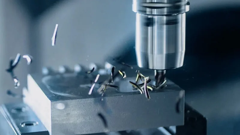
Not every project starts with high volume. Prototypes, clinical trials, and low-volume specialty devices need a different approach. CNC machining fills that gap.
Material Versatility and Rapid Iteration
CNC machining works directly from CAD files. Same-day revisions are possible. Development timelines can compress by 50–70% compared to waiting for molded parts. That speed matters when you’re iterating on a design.
The material versatility is unmatched. CNC mills handle metals like aluminum and titanium, plus plastics like nylon, PEEK, and ABS. You can prototype with the exact material intended for final production. That means meaningful testing for strength, chemical resistance, sterilization compatibility, and thermal stability—not just geometry checks.
No tooling required. No expensive molds to cut before you see a single part. For low-volume prototyping where design changes happen frequently, this eliminates a huge cost barrier.
Surface Finish and Secondary Operations
CNC machining achieves tolerances as tight as ±0.005 mm. That precision is essential for optical housings that require exact alignment. But surface finish needs attention. Machined surfaces show tool marks that can scatter light. Secondary operations like bead blasting, anodizing, or polishing address this.
For aluminum housings, anodization adds a hard, corrosion-resistant layer. It also creates a matte finish that reduces internal reflections. For plastic parts, vapor polishing or abrasive finishing smooths machined surfaces to optical quality.
Additive Manufacturing for Complex Geometries
Additive manufacturing, or 3D printing, opens design possibilities that traditional methods cannot match.
Design Freedom and Internal Channel Creation
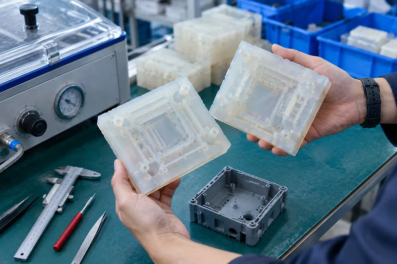
With 3D printing, you can create internal channels for cooling or light routing that would be impossible to machine or mold. Lattice structures reduce weight while maintaining strength. Complex curves and organic shapes come directly from CAD files without tooling constraints.
This technology shines for patient-specific anatomical models, surgical guides, and custom prosthetics. These applications need unique geometries tailored to individual patients. No mold can justify that level of customization.
Material Limitations and Post-Processing Needs
But 3D printing has limits. Material options are narrower than CNC machining or injection molding. Many printable resins lack the long-term stability required for medical device housing applications. Layer lines create weak points and surface roughness that affects optical performance.
Post-processing is mandatory. Parts need cleaning to remove support material. Surface smoothing improves aesthetics and reduces bacterial harboring sites. Some materials require UV curing or heat treatment to achieve final properties. These steps add time and cost.
For functional prototypes, 3D printing works well. For production parts, it suits only low volumes or highly customized items. The trade-off between design freedom and material performance must be weighed carefully.
Making the Right Choice
Your decision hinges on volume, tolerance, and material requirements. High volume with tight tolerances? Injection molding wins. Rapid iteration with material flexibility? CNC machining leads. Complex geometry with customization? Additive manufacturing steps in.
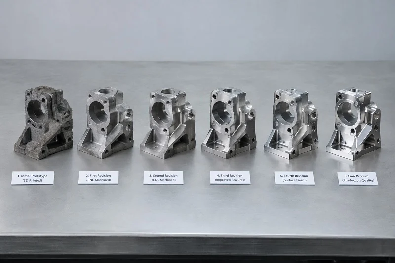
Many projects use a combination. Prototype with CNC machining, validate the design, then transition to injection molding for production. This hybrid approach de-risks the development process.
Working with a partner who understands all three methods simplifies this journey. NOBLE, a leading manufacturing partner in China, offers exceptional service capabilities and professional machining expertise. They help clients efficiently complete prototyping and mass production under one roof. Their in-house tooling and precision machining capabilities mean you don’t juggle multiple vendors.
The right manufacturing process depends on your specific situation. Define your requirements, evaluate your options, and choose deliberately. Your medical optical housing deserves nothing less.
Decision Framework for Medical Optical Housing
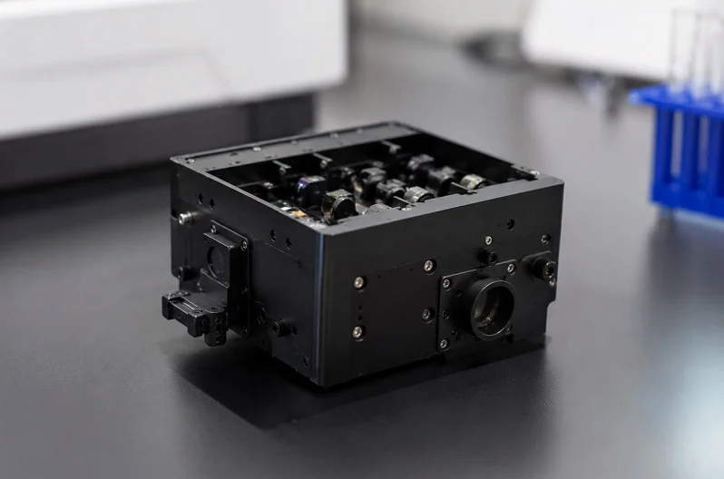
You now have all the facts about materials and processes. Next, you need a clear plan to pick the best option. This framework gives you three simple steps. Follow them in order.
Step 1: Risk Assessment and Clinical Use Case Analysis
Start by looking at how the device will be used. Where will it work? An endoscope in an operating room faces different risks than a handheld tool in a clinic. The sterilization method, the chemicals it touches, and the drop height all change based on the use case.
List every possible failure. What happens if the housing cracks? What if moisture gets inside? What if the optical alignment shifts by 10 microns? Give each scenario a risk level. High-risk items become must-have requirements. Low-risk items become areas where you can make trade-offs.
This is also the time to bring in your manufacturing partner. The micro-optic world has high costs and high risks. Few qualified manufacturers exist. You need to treat them as product development partners, not job shops. Only by adding their micro-manufacturing expertise early can you get a cost-effective solution. That directly reduces the risk of picking the wrong materials or processes.
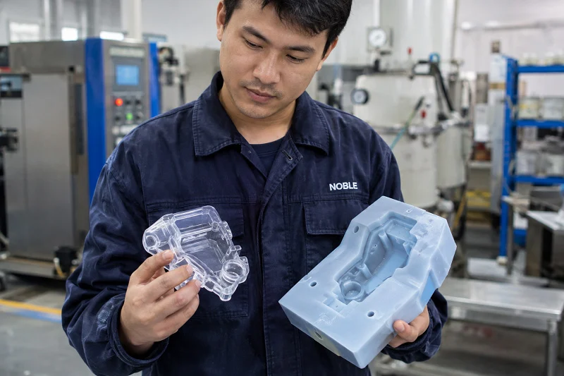
One project shows why this matters. An optical design left almost no room for gate and ejector placement. The issue was not visible in CAD. It only showed up during simulation and tooling design. The team worked with the client and made a small adjustment. They shifted the parting line and optimized the draft angle. The optical function stayed intact. The prototype worked immediately. Series production ran without errors. That collaboration simplifies compliance because the design is already validated.
Step 2: Scoring Against Cost, Volume, and Tolerance Targets
Now you have your requirements. Rank them against your targets. Build a simple scorecard. List each material-process combination for your medical optical housing. Score it on cost per part, volume fit, and tolerance capability.
Cost matters, but it is not the only factor. A cheap material that fails sterilization costs more than an expensive one that works. Volume drives process choice. High volume pushes you toward injection molding. Low volume favors CNC machining. Tolerance requirements narrow your options further.
Remember that material selection is a long-term decision. You cannot swap resins easily after tooling is cut. Check every material against your regulatory and safety requirements. If a material fails any one of these checks, it is out. No exceptions. Performance criteria like dimensional stability, chemical resistance, and mechanical strength must all pass. The mechanical properties of your chosen material directly affect the housing’s ability to maintain optical alignment over time.
Step 3: Iterative Design Refinement and DFM Optimization
The first design is never the final design. You need to refine it through iteration. Start with advanced CAD and parametric design tools. SolidWorks and similar platforms let you run rapid iterations across subsystems. Define your critical interfaces early. Run interference and clearance analysis to catch integration issues before prototyping.
Use finite element analysis to optimize structural integrity. Run thermal simulations to validate performance. These engineering processes turn guesswork into data.
Tolerance analysis deserves special attention. Use sensitivity and Monte Carlo simulations in optical design software. These tools predict manufacturing requirements and estimate performance levels for different alignment approaches. Compare passive alignment with active alignment. Passive alignment uses forgiving tolerances for fast assembly. Active alignment achieves tighter tolerances at lower cost when needed. The right choice depends on your specific application.
Get your production team involved during the design phase. They provide practical guidance on optical interfaces and assembly techniques. Their input during design saves headaches during production. Automated prototyping platforms with robotics and vision systems enable quick design iterations. They help you transition to scaled production with confidence.
Key Design Considerations for Medical Device Housing
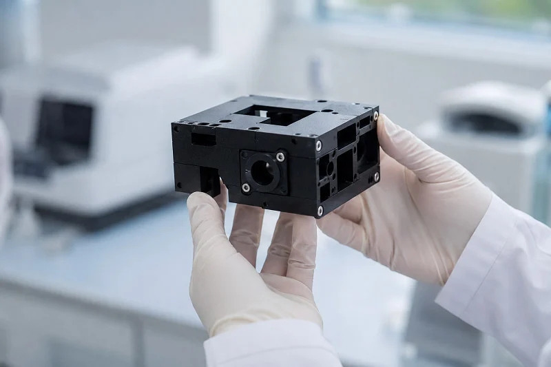
Small design choices affect how well the medical device housing works and how easy it is to make. Three areas need attention: joining methods, wall geometry, and sealing.
Snap-Fit vs. Screws and Adhesive Bonding
Snap-fits allow fast assembly. But the plastic arms relax over time, and the holding force drops. This stress relaxation slowly shifts the optical alignment. For medical device housing that needs stable positioning, snap-fits need careful design.
Screws provide more reliable clamping force. They keep preload over time. But they add parts and assembly steps. You need boss designs that handle stress without cracking. The internal radius at the base of the boss should be at least 50% of the wall thickness. Sharp internal corners create stress concentration points. If space is tight, 25% is the minimum.
Adhesive bonding spreads the load across a wider area and seals the joint. The downside is cure time and process control. For optical housings, adhesives avoid stress points that mechanical fasteners create.
Uniform Wall Thickness and Rib Design Strategies
Wall thickness drives everything in injection molding. Non-uniform walls cause sink marks, voids, and warpage. Keep wall thickness consistent. For most thermoplastics, 2 to 4 mm works well.
Ribs add stiffness without making the wall thicker. Keep ribs at 40 to 60% of the nominal wall thickness. For a 2 mm wall, ribs should be 0.8 to 1.2 mm. A rib nearly as thick as the main wall creates a sink mark on the opposite surface. For optical housings, that sink mark can appear on the lens mounting surface.
Change wall thickness gradually. Avoid direct transitions from 1.5 mm to 4 mm. The thin section freezes early, blocking packing pressure. The thick section continues to shrink, causing warpage.
Coring out heavy sections helps. Solid bosses contain excess material that stays hot after ejection. Coring brings local thickness closer to the nominal wall while maintaining strength.
Corner design matters too. The external radius should equal the internal radius plus the wall thickness. Both radii share the same center point. Adding only an internal radius makes the corner thicker than adjoining walls.
IP Ratings and Fluid Ingress Protection
Medical devices face fluids every day. Blood, saline, and disinfectants find their way into housings. The IP rating system tells you how well your medical device housing resists ingress. IP54 is common for general use. IP67 means the housing can survive temporary immersion.
Sealing starts with the parting line. A flat seal surface is easier to gasket than a curved one. Snap-fits alone rarely provide adequate sealing. You usually need a gasket or adhesive bond line. The same principles apply to buttons, connectors, and vents. Each opening is a potential leak path.
Your choice of materials also affects sealing. TPE overmolding creates an integrated seal without separate gaskets. But the material properties must match the sterilization requirements. A soft seal that degrades after gamma sterilization does you no good.
Partnering with NOBLE for Medical Optical Housing
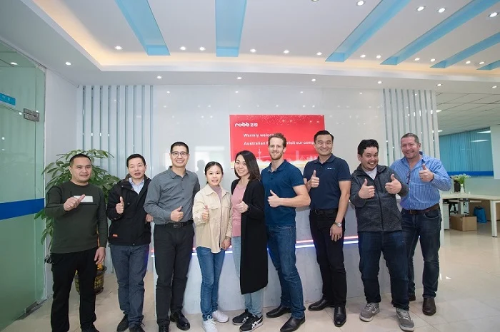
You now have the plan, the materials, and the methods. The next step is finding a partner who can bring it all together. NOBLE can do that for you. They make material and process choices easier by offering everything in one place. You do not have to manage many vendors. You do not have to worry about gaps between design and production. One team handles the entire journey.
Full-Service Capabilities from Design to Assembly
NOBLE does more than make parts. They help you from the first idea to the final assembled product. This full-service approach makes your development process smoother.
In-House Tooling and Rapid Prototyping
Slow tooling can ruin a project. NOBLE makes molds in-house, so lead times drop a lot. You get prototype parts in days, not weeks. That speed lets you test your medical device housing design early and often. You find problems before they turn into costly errors.
Rapid prototyping also lets you test material and process combinations before you commit to production tooling. Try that new polymer. Test that surface finish. Confirm the sterilization compatibility. All without waiting months for a mold. This step-by-step approach lowers risk for your whole project.
Precision Machining and Injection Molding Expertise
NOBLE has deep experience in both CNC machining and injection molding. For prototypes and low volumes, their precision machining gives you tight tolerances and material flexibility. For high-volume production, their injection molding expertise ensures consistent quality across thousands of parts.
Here is the key point: injection molding must be controlled at every step. Melt temperature, cavity pressure, cooling rate—each one affects the final part. NOBLE’s team watches these factors closely. They use scientific molding methods to keep things consistent. The result is optical housings that hold their alignment cycle after cycle.
Certifications and Quality Assurance Systems
Medical devices need strict quality systems. NOBLE’s certifications show they take this seriously. You get documented proof of quality at every stage.
ISO 9001:2015 and ISO 13485:2016 Compliance
ISO 9001:2015 covers general quality management. ISO 13485:2016 goes further. It addresses the specific needs of medical device manufacturing. Both certifications mean NOBLE’s processes meet international standards for quality and regulatory compliance.
These certifications matter for your regulatory submission. When you document your supply chain, you can point to NOBLE’s certified systems. That documentation makes your path to market easier. It shows auditors that your manufacturing partner follows established protocols.
Rigorous Inspection and Documentation Protocols
Quality does not stop at certifications. NOBLE keeps detailed inspection protocols for every part. Dimensional checks, surface finish verification, material traceability—all documented. You get complete records with every shipment.
This documentation supports your regulatory compliance efforts. It provides proof that your medical device housing meets specifications. It also helps with root cause analysis if problems come up later. You can trace any issue back to its source quickly.
The partnership goes beyond production. NOBLE’s engineers offer design support during development. They review your CAD files for manufacturability. They suggest improvements to cut costs. They help you pick materials that balance performance and budget. For complex projects like surgical guides or diagnostic instruments, this early teamwork prevents costly redesigns.
Working with NOBLE means you have a team that sees the whole picture. They know that material choice affects manufacturing. They know that manufacturing affects quality. They know that quality affects regulatory approval. Every decision connects to the next one. Having one partner who sees the entire chain makes your job easier.
There is no single best material or process for a medical optical housing. The right choice depends on your specific application. Sterilization needs, tolerance targets, and production volume all shape the decision. Define your functional requirements first. Evaluate materials against real-world conditions. Then match those materials to manufacturing methods that deliver quality at scale.
This process works best when you collaborate early. Design engineers, materials specialists, and manufacturing partners should talk before tooling begins. That collaboration prevents costly redesigns later.
A full-service partner like NOBLE simplifies this journey. Their ISO-certified processes and in-house capabilities de-risk your project. Your medical devices reach market faster. Your medical technology performs reliably. And your housing meets every regulatory and cost objective.
FAQs of Medical Optical Housing
How do you pick between plastic and metal for your medical optical housing?
Begin with your sterilization method and heat load. Plastics like polycarbonate work well for most diagnostic devices. Metals like aluminum handle heat and EMI better. If your device makes a lot of heat or sits near MRI equipment, metal wins. Otherwise, plastic saves weight and cost.
Can you use the same material for prototyping and production?
Yes, and you should. CNC machining lets you prototype with the exact resin meant for injection molding. That way, you test real material properties—chemical resistance, sterilization compatibility, dimensional stability—not just shape. Switching materials between prototype and production risks finding problems too late.
What tolerance can you really get for optical alignment features?
Precision injection molding holds key features to ±5 microns using scientific molding methods. Standard injection molding reaches 0.125 mm repeatably. CNC machining reaches ±0.005 mm. Your target depends on the optical design and assembly method. Active alignment during assembly can relax housing tolerances a lot.
How many parts justify injection molding over CNC machining?
There’s no magic number, but the crossover usually lands in the low thousands. Injection molding needs expensive tooling up front. CNC machining has no tooling cost but a higher per-part price. Run a simple break-even calculation with your target volume. For clinical trials and early launches, CNC machining often makes more sense.
What sterilization method is easiest on housing materials?
EtO sterilization puts the least heat stress on polymers. Autoclave cycles above 120°C rule out many plastics. Gamma radiation breaks polymer chains over time, limiting reuse. If your device must survive repeated autoclaving, think about aluminum or stainless steel. For single-use devices, EtO-compatible plastics work well.
When should you bring a manufacturing partner into the design process?
Bring them in during Step 1 of the decision framework—risk assessment. Early teamwork prevents costly redesigns. A partner can spot manufacturability issues in CAD that you might miss. They can suggest gate placement, draft angles, and wall thickness changes before tooling begins. That input saves months and thousands of dollars.