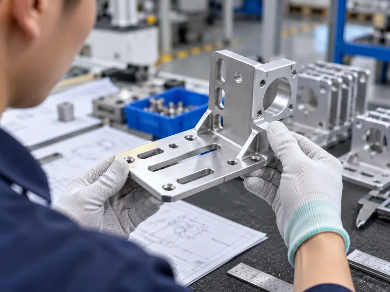
A robot sensor mount keeps sensors firmly in place. Making one requires very high precision. A mount that is not precise causes sensor misalignment. This leads straight to poor data, calibration drift, and eventually system failure. Avoiding these serious problems begins with the right practical approach. Material choice, machining methods, and strict tolerance control define a successful design. These basics keep a robot working reliably in tough conditions.
Best Practices for a Robot Sensor Mount
Design for Manufacturability
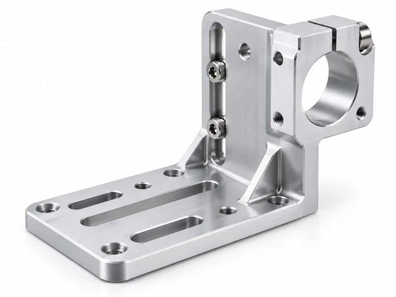
Good design for manufacturability starts before you even begin cutting. Deep pockets and sharp internal corners slow the cutting tool and raise costs. Keeping shapes simple reduces tool wear and gets parts off the machine faster. You should standardize pocket radii. Make corner radii at least one-third of pocket depth. For example, use an R5 mm fillet for a 15 mm deep pocket, so rigid endmills can cut at full speed. Keep line-of-sight clearance for the spindle by adding at least 15 degrees of draft around deep bearing bores to prevent collisions. Avoid micro-threaded blind holes by designing tapped holes with enough tap drill relief, at least two times the pitch deeper than the usable thread. Use bearing journal fillets of R0.2 mm to R0.4 mm with undercut relief grooves so bearings sit flush against shoulder faces without corner radius interference.
Functional tolerancing also matters a lot. Avoid adding unnecessary tight specs. Tightening tolerances below normal functional ranges, like plus or minus 0.02 to 0.05 mm, often raises cost without making the system work better. A robot sensor mount does not need every surface to be as tight as possible. Precision machining allows single-piece mounts with better flatness, alignment, and damping for robot sensor stability. Robotics projects use machined bases, plates, brackets, and mounting features to support sensors, motors, and joints. Every extra tight tolerance you add without a good reason only adds cost and lead time.
Early Sensor and Mount Co-Design
You should design the sensor and mount together early in the design phase. A camera bracket that bends or moves causes misalignment. The same is true for LiDAR units and encoders. When you co-design, you can define the mounting shape and alignment features as one system. This stops stress from misaligned holes and signal interference from bad grounding. The mounting faces must be flat within 0.02 mm, and hole positions must be accurate to avoid stress on the sensor body. If you wait until after choosing the sensor to design the mount, you often end up with compromises that hurt performance.
Co-design also helps with cable routing and connector access. You should plan how wires will run and where connectors will sit. A mount that blocks a connector or forces a sharp cable bend will cause problems later. Early teamwork between the sensor team and the mechanical team saves time and money. It also makes sure that manufacturing robotic sensor-mounted components stays simple and repeatable.
Prototype Validation
Prototype validation proves the design works before you start production. For flatness, the evaluation must let enclosing planes find their orientation without depending on the opposite face. A raw indicator range from a tilted setup is not a valid flatness result. Leveling only three points does not give the smallest enclosing zone for the whole surface. You need to keep both orientation and surface shape in CMM evaluation. Comparing just the angle between two fitted planes is not enough. It shows relative orientation but can miss surface peaks and valleys.
Pick enough points to measure. Few points can miss bowing or waviness between them. A program’s minimum point count for making a plane does not mean the whole face has been checked well. The coverage must match the surface and tolerance. Define and control how the part is supported. Clamping a thin plate can change the shape being inspected. If you accept the part under a clamped condition, define the supports and clamps. If you accept it in a free state, use a setup that matches that. Do not increase clamping force just to get a passing reading. Specify height and support condition separately. Parallelism does not set the distance between the controlled face and datum A. Define the required thickness or location separately, and read it along with the geometric controls.
When reviewing the report, check that datum construction, surface extent, sampling strategy, evaluation method, and support condition are all identified and match the drawing requirements. The table below shows common inspection methods and how well they work for a 0.02 mm flatness requirement.
| Inspection Method | Achievable Accuracy | Suitability for 0.02 mm Flatness |
| Digital Calipers | ±0.02 mm | Not reliable — accuracy equals the tolerance, no GD&T capability |
| Micrometer | ±0.002 mm | Single-axis only; cannot measure surface form |
| Height Gauge + Surface Plate | ±0.01 mm | Suitable for 2D flatness/parallelism; limited to datum-accessible features |
| CMM (Coordinate Measuring Machine) | ±0.001–0.005 mm | Best for full GD&T, true position, complex profiles, FAI reports |
| Optical Comparator / Vision System | ±0.005 mm | Limited to surface-accessible features; no Z-axis depth |
| 3D Scanning (structured light) | ±0.02–0.05 mm | Not suitable for tight-tolerance bore or position inspection |
The key rule from NIST says that measurement equipment must be at least four times more accurate than the tolerance being checked. For 0.02 mm flatness, this means equipment with MPE ≤ 0.005 mm, which effectively requires CMM verification. CNC machining makes sensor mounting bases with precise shape and size, ensuring accurate sensor installation and stable performance. Use the 0.02 mm flatness benchmark as a real example of precision manufacturing needs. A robot sensor mount that passes prototype validation with these methods will work reliably in production.
Design Considerations for Robotic Sensor-Mounted Components
Mounting Geometry and Alignment
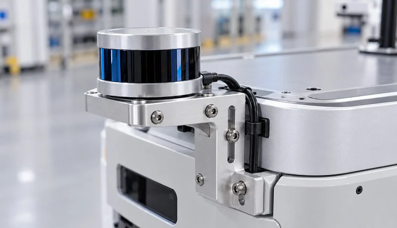
Sensor brackets hold cameras, LiDAR units, and encoders. A bracket that bends or moves causes misalignment. That misalignment ruins your data. So the mounting geometry must hold everything in place. Mounted faces must be flat within 0.02 mm. Hole positions must be exact to avoid stress on the sensor body. If a hole is off by even a tiny amount, the sensor body bends when you tighten the screws. That stress changes how the sensor reads the world.
From a real-world view, think about how the sensor sits on the robot. The mounting face is the base. A flat face keeps the sensor steady. Exact holes keep the sensor from twisting. When you design sensor mounting bases, remember that each feature affects the next one. A small error in hole location creates a big error at the sensor tip. That is why tight tolerances matter so much here. They are not just numbers on a drawing. They are the difference between clean data and always having to recalibrate.
Vibration Damping and Rigidity
Robots move. Motors spin. Joints rotate. All that motion creates vibration. A robot sensor mount must handle that vibration without letting the sensor shake. Rigidity keeps the sensor still. Damping soaks up the energy before it reaches the sensor. You need both. A mount that is too flexible will let the sensor wobble. A mount that is too rigid but has no damping will pass every shock straight through.
It is worth noting that the material you pick plays a big role here. Aluminum gives you a good mix of stiffness and weight. Stainless steel adds more mass and rigidity. Engineering plastics like PEEK or Delrin can damp vibrations better than metal in some cases. Carbon fiber reinforced options offer high stiffness with low weight. The right pick depends on your robot and your sensor. A heavy mount on a small arm slows everything down. A light mount on a big robot might not hold steady. Match the material to the job.
Cable Routing and Connector Access
Cables carry power and data to your sensors. Bad routing kills signal quality. Over-tightened cable ties can damage shield jackets and conductors. That damage weakens EMI protection in tight sensor mounts. Velcro ties are a better choice because they are less harsh on the cable. Cable clip holders also work well. If you really have to use plastic cable ties, weaving two of them together — one around the arm and the other around the cable — is a safer option for the cable.
Good routing follows a few simple rules. Bend in the best direction first. Keep all conductors at the same lengths to preserve timing alignment. Apply a controlled 90° twist along the connector length, following the cable’s natural lay. Avoid over-tight bundling because tight bundles resist proper twisting and can deform the dielectric. Provide stress relief at cable exits. Keep power and data cables apart to reduce electromagnetic interference. Manage slack carefully with Velcro straps and cable managers.
The table below shows key practices for preventing EMI in tight spaces.
| Best Practice | Why It Prevents EMI |
| Use individually shielded pairs for encoder signals | Prevents noise coupling into low-voltage signal lines |
| Select braided shields (85%+ coverage) for flex zones | Maintains shield integrity over millions of flex cycles |
| Terminate shields at both ends | Prevents the shield from acting as an antenna |
| Separate power and signal cables by at least 50mm | Reduces coupling from PWM servo noise |
| Cross power and signal cables at 90° angles | Minimizes coupling at crossing points |
Avoid these common mistakes: unshielded cables for signals below 1V, foil-only shielding that cracks under flex, running power and signal in the same bundle, improper shield termination, and shield degradation from torsion. Good cable routing protects your sensor mounting hardware and keeps your data clean.
Materials for a Robot Sensor Mount
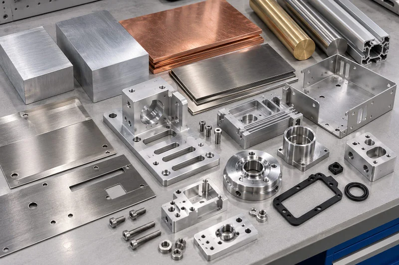
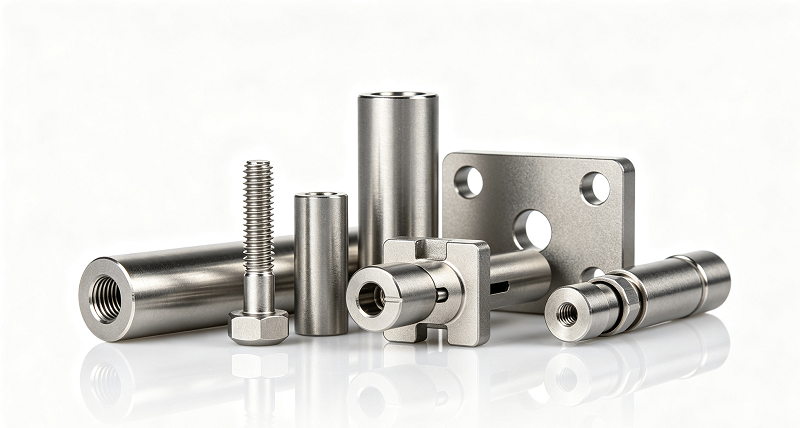
Choosing the right material for a robot sensor mount affects everything else. It changes weight, stiffness, rust resistance, and cost. CNC machined sensor and encoder mounts can be made from aluminum or stainless steel. Common parts include encoder brackets, LiDAR mounts, camera brackets, and force sensor flanges. Each material brings its own benefits.
Aluminum Alloys
Aluminum is the most common choice for robot sensor mount projects. It has a great strength-to-weight ratio. That matters a lot for mobile robots and drones. The 6061 alloy is a good choice for robotics and automation, including sensor mounts. It keeps its shape well and is easy to machine. Its typical yield strength ranges from 240 to 276 MPa in the T651 temper. That is about 40 ksi. This strength works for most sensor mounts without adding extra weight.
Aluminum CNC machining for robotics supports stronger prototypes, precise moving parts, and faster product development. You can test a design, change it, and test again quickly. That speed helps teams move from idea to production without long waits. The material also resists rust well in normal conditions. It does need a coating or anodizing for harsh conditions.
Stainless Steel
Stainless steel is used in tough environments. Salt water, harsh chemicals, and food-grade settings need more than aluminum can offer. Aluminum will pit and rust without expensive coatings in these conditions. Stainless steel 316 works well in marine, chemical, and medical settings. Its molybdenum content stops chloride damage. That makes it a good choice for marine deck hardware and similar use.
For food-grade or medical sterilization, 304 or 316 stainless steel is the standard. The non-porous surface resists bacterial growth and handles repeated cleaning. The extra cost acts as insurance against failure. Weight is the trade-off. Stainless steel is heavier than aluminum. So for aerospace or mobile robots where weight is critical, aluminum still wins. The choice depends on your environment and weight limits.
Engineering Plastics
PEEK and Delrin
PEEK and Delrin have special benefits for a robot sensor mount. These plastics reduce vibrations better than metal in many cases. They also stand up to chemicals and don’t need oil. PEEK works well at high heat. Delrin keeps its shape well and has a smooth surface. Both materials are good for robot sensor housings that need electrical insulation. They weigh less than aluminum and stainless steel. That helps when weight matters.
Carbon Fiber Reinforced Options
Carbon fiber reinforced plastics are very stiff and light. They don’t wear out easily and keep their shape under pressure. These composites are good for precise work where parts must not expand much with heat. The downside is high cost and hard to machine. Carbon fiber can be hard to cut without layers separating. It also can conduct electricity, so you might need extra insulation for sensitive electronics.
Machining Processes for a Robot Sensor Mount
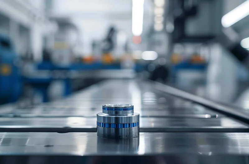
CNC machining for robotics makes precise robot parts like arms, joints, gears, and grippers with tight tolerances for smooth motion. The same processes create the robot sensor mount that holds your camera, LiDAR, or encoder. If the machining is done right, the sensor stays lined up for years. If it is done wrong, you will deal with calibration drift forever.
CNC Milling and Turning
CNC milling and turning are the main methods for precision manufacturing of a robot sensor mount. A 5-axis mill cuts angled holes and locating bores in one setup. That is important because each extra setup adds stack-up error. The table below shows what 5-axis and 3-axis setups achieve on aluminum sensor mounts.
| Machining Setup | Material / Component | Angled Hole Position Tolerance | Notes |
| 5-axis (single setup) | 7075 Aluminum (humanoid robot joint housing) | ±0.008 mm | Sensor mounts listed as an application |
| 5-axis (single setup) | 7075-T6 Aluminum (UAV curved frame) | ±0.010 mm | — |
| 5-axis (single setup) | General angled holes/locating bores | ±0.008 – ±0.012 mm | No stack-up risk |
| 3-axis (multi-setup) | General | ±0.03 mm minimum | Stack-up errors double or triple tolerance values |
Five-axis cuts alignment errors by up to 80% compared to multi-setup 3-axis machining. That is a huge gain for high-accuracy parts. In a practical sense, a single setup also saves time and labor.
Material stability is just as important. In T6 processing, solution heat treatment at 530°C followed by cold water quench creates a steep internal stress gradient. The outer surface sits in compression at -80 to -120 MPa, while the core pulls in tension at +80 to +120 MPa. Cutting away material for monolithic sensor brackets destroys that balance. The part bows outward and breaks flatness tolerances. Pre-stretched T651 temper lowers peak internal stresses to under ±15 MPa. That improves dimensional stability and keeps your robot sensor mount flat.
Two rules keep thin walls and threads safe. Stay away from wall thicknesses below 0.8 mm on tall unsupported vertical fins with an H/t ratio above 10. If you don’t, you get elastic deflection, taper errors, and chatter marks. Thread engagement depth should not go past 2.0 times the nominal thread diameter. Deeper threads give no strength gain and raise tap breakage risk.
Drilling and Tapping
Drilling and tapping need the same care as milling. Tool coating choice changes everything on aluminum. Polished uncoated micro-grain carbide offers good chemical compatibility, a friction coefficient of 0.30-0.40, and a max temperature of 600°C. Titanium Diboride PVD is chemically inert with friction at 0.15-0.22 and a max temperature of 850°C. Diamond-Like Carbon gives ultra-low friction at 0.05-0.10 and suits dry finishing, though it tops out at 450°C. Polycrystalline Diamond inserts last longest with friction at 0.05-0.08 for high-silicon aluminum. Stay away from TiAlN and AlCrN coatings. They fail badly from chemical galling on aluminum.
Vibration loosening is a real threat on a robot. Nord-Lock wedge washers pass the Junker test at 14g for over 2,000 cycles and keep roughly 100% of their tension after 1,000 cycles. Serrated flange nuts hold about 85-90%. Nyloc nuts manage 70-80% but degrade above 250°F. Split lock washers lose all tension within 100 cycles, and NASA rejects them. For tapped holes in aluminum, engage 2x diameter to prevent thread stripping. A stripped M10 hole repaired with a Heli-Coil kit restored factory torque to about 18 ft-lb and held through 4,000 miles of driving.
Surface Finishing
The best surface finish for robotic tactile sensor mounts depends on the specific sensor requirements and application. Best practices are tailored for CNC machining. A tactile sensor needs a smooth, consistent face to read force evenly. An optical sensor mount may need a matte, non-reflective finish to cut stray light. In a practical sense, you should match the finish to the sensor, not to a generic spec sheet.
NOBLE, a leading manufacturing company in China, brings exceptional service capabilities and professional machining expertise to this work. Their team helps clients complete prototyping and mass production efficiently. Whether you need one robot sensor mount or a full production run, the right partner keeps your tolerances tight and your schedule on track.
Precision Manufacturing Tolerances for a Robot Sensor Mount
Typical Tolerance Ranges
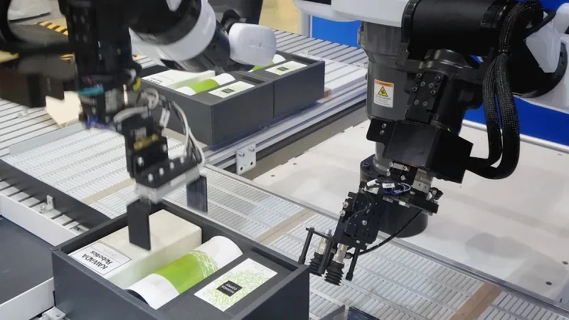
Making a robot sensor mount with precision starts with smart tolerance choices. The main benchmark is flatness. Mounting faces must be flat within 0.02 mm. A face that fails this spec will twist the sensor body when screws tighten. That twist causes poor readings and calibration drift. The 0.02 mm number comes from years of real experience in robotics. It is tight enough to stop stress on the sensor body. It is loose enough to machine steadily without raising cost.
Typical ranges for sensor mounting bases fall into a few clear groups. Critical mounting faces need 0.02 mm flatness or better. Locating pin holes need ±0.013 mm. Datum surfaces for alignment need 0.01 mm surface profile. Non-critical surfaces can go to 0.1 mm. Making tolerances too tight everywhere adds cost without helping performance. Apply tight tolerances only where the sensor touches the mount. That keeps production costs fair and quality high.
CNC machining makes sure sensor mounting bases for robots are built precisely. That gives you accurate sensor installation and stable performance over many cycles. Tight tolerance control matters where the sensor body touches the mount. A mount with good control will work reliably for years. The upfront cost gap between a loose-machined mount and a precision-machined one is small next to field failure costs. Field failures mean lost production time, replacement labor, and sensor recalibration.
Think about a LiDAR mount with 0.05 mm flatness error instead of 0.02 mm. The laser beam angle shifts by a tiny amount. At 10 meters, that shift creates centimeters of position error. The robot misses its target completely. That is why tight tolerances in precision manufacturing matter for robotic sensor-mounted parts. Every micron of error at the mount grows into larger errors at the sensor tip.
In-Process Measurement
Measuring during production saves time and cuts scrap. Check critical features while the part stays in the fixture. A CMM is the standard tool for checking 0.02 mm flatness. NIST rules say your measurement equipment must be four times more accurate than the tolerance you check. For 0.02 mm flatness, you need equipment with maximum permissible error of 0.005 mm or better. Only a CMM or precision comparator can reach that reliably.
Spindle-mounted probes check hole positions and surface heights during cutting. If a bore is off by 0.01 mm, you adjust the tool offset and re-cut right away. This process is called in-process correction. It stops scrap and keeps production running smoothly. A thin plate can flex during cutting and spring back when released from the fixture. Measuring under clamp does not give the final free-state result. You need a separate measurement step after unclamping to get true flatness.
For high-volume runs, use statistical process control. Measure every nth part and watch the trend lines. If flatness drifts toward 0.025 mm across several parts, the tool is wearing or coolant chemistry needs adjustment. This proactive approach keeps tolerances under control without measuring every single part. Precision machining makes measurement a natural part of the process rather than a separate inspection step at the end. Combine tight control with in-process checks for consistent results across every batch.
Fixturing and Workholding
Fixturing decides where things are won or lost in precision work. A part that shifts during cutting cannot hold 0.02 mm flatness. For a robot sensor mount needing this spec, the fixture must be rigid. Any flex in the fixture transfers straight into the part. The machine spindle also needs rigidity. Two methods work well for batch-machining thin plates: soft-jaw vises and vacuum workholding fixtures.
- Vacuum fixtures with minimal mechanical backup stop distortion on thin plates. They give full-surface finish access without deflection. Consistent locating features in the fixture design keep part positioning identical. This boosts repeatability across batch production without rework.
- Custom-machined soft jaws match the part profile precisely. They cut down distortion during cutting. The uniform grip lowers the chance of deformation. You can remachine the soft jaws to fit the same part many times. This keeps positioning consistent across production batches. Each part nests perfectly every time. That improves accuracy and repeatability for delicate parts like thin sensor mount plates.
The choice between vacuum and soft jaws depends on part size and production volume. Vacuum works best for large thin plates with a flat sealing surface. Soft jaws work better for smaller parts with complex contours. Both methods beat standard hard jaws or clamps at holding tight tolerances.
Good fixturing also cuts setup time during changeovers. The fixture positions each part the same way shift after shift. That cuts cycle time and keeps quality steady throughout production. For high-volume production of sensor-mounted parts, this consistency is critical for manufacturing for robotic sensor-mounted parts. Every second saved in changeover adds up across hundreds or thousands of parts.
High-precision machining demands attention to every detail. Fixturing is one of those details that separates good parts from great ones. Combine proper fixturing with tight control and in-process measurement. Micron-level accuracy becomes achievable and repeatable part after part. The result is a robot sensor mount that performs exactly as designed over its entire service life.
Precision and Integration Challenges for a Robot Sensor Mount
Thermal Expansion and Stability
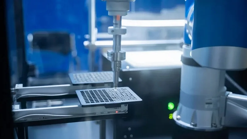
Heat changes everything. A robot arm running all day gets warm. That warmth makes metal grow. If your robot sensor mount grows unevenly, the sensor shifts. A camera that was aligned at 20°C may point slightly off at 50°C. The error looks small. At the end of a long arm, it becomes large.
Material choice drives this problem. Aluminum expands more than stainless steel. That is why pre-stretched T651 temper matters. It lowers peak internal stresses to under ±15 MPa. A stable mount holds its shape across temperature swings. From a practical perspective, you should test your mount at the high and low ends of its working range. If the sensor drifts, add a thermal compensation step or switch to a lower-expansion alloy.
Electronics and Wiring Integration
Wires are the weak link in many robotic sensor-mounted components. A perfect mount still fails if a cable pulls loose or picks up noise. Poor grounding is a common failure point. It sends interference straight into your signal. The sensor reads garbage, and you blame the mount.
Good integration starts with planning. Route power and signal cables apart. Keep them at least 50 mm apart to cut coupling from servo noise. Cross them at 90° angles when they must meet. Use individually shielded pairs for encoder signals. Pick braided shields with 85% or more coverage for flex zones. Terminate shields at both ends so they do not act like antennas. These steps protect signal accuracy and keep your data clean.
Vibration and EMI Reduction
Robots shake. Motors hum. Joints snap back and forth. A robot sensor mount must soak up that energy without letting the sensor move. Loose fasteners make it worse. Nord-Lock wedge washers pass the Junker test at 14g for over 2,000 cycles. They keep roughly 100% of their tension after 1,000 cycles. Split lock washers lose all tension within 100 cycles. NASA rejects them for good reason.
EMI is the silent partner to vibration. A vibrating cable can rub through its shield. Once the shield fails, noise floods the signal line. Tight tolerances on cable routing and connector placement help here. So does a rigid mount that stops relative motion between parts. Optimizing the manufacturing for robotic sensor-mounted components means solving these problems together. Stress from misaligned holes and signal interference from poor grounding are the two most common failure points. Fix both at the design stage, and your precision manufacturing effort pays off in the field.
Scaling Manufacturing for a Robot Sensor Mount
Low-Volume Prototyping
You have a design. Now you need to prove it works before spending big money on production tooling. Rapid prototyping gives you that chance. The method you pick depends on what you need to test. If tight tolerances below ±0.05 mm matter, choose CNC or add post-processing and inspection to additive parts. CNC machined plastic like Delrin or PEEK holds ±0.05 mm or better. That makes it the best choice for mating features, controlled fits, sealing surfaces, and threaded interfaces before metal CNC runs. SLA gives you fine feature resolution and surface quality. It works well for form and fine geometry, but not for structural testing. SLS and MJF typically achieve ±0.2–0.5 mm for general features. Vacuum casting lands at ±0.1–0.3 mm depending on the mold and material.
For high-fidelity testing before metal CNC runs, CNC machined plastic such as Delrin is recommended because CNC can hold tolerances of ±0.05 mm or better, which supports tight mating features and controlled fits.
The transition from prototype to production does not have to break your tolerance control. Aluminum CNC machining supports faster product development. That speed helps you bridge prototyping and production without losing the precision you built into the design. You test the geometry, fix what needs fixing, and move forward with confidence.
High-Volume Production
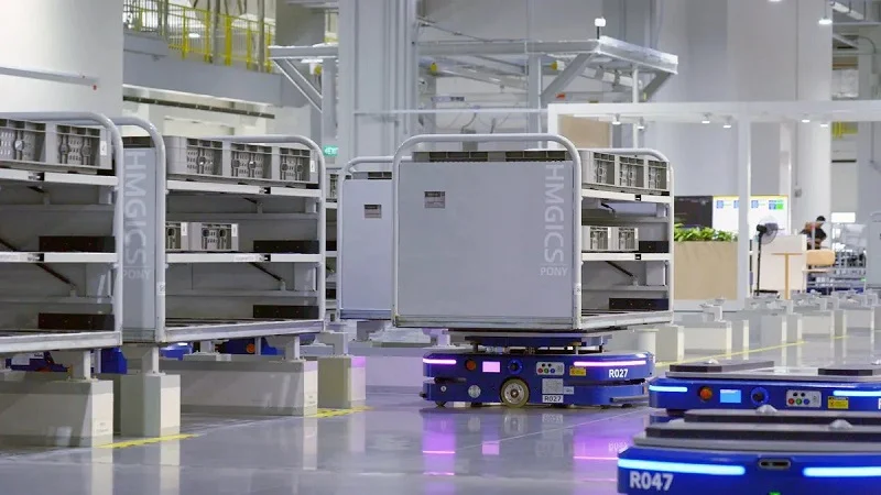
Scaling up means keeping the same quality across thousands of parts. Automated pallet systems make that possible. These systems run consistent production around the clock. They cut variation between parts. In-line metrology checks critical features in real time. That keeps your process stable and your CpK above 1.33. Statistical process control tracks process centering and spread. For a robot sensor mount with ±0.05 mm tolerances, SPC helps you hold CpK between 1.33 and 1.67. Even tighter features at ±0.01 mm can stay capable through process optimization.
The robot sensor mount you make on part one must match part ten thousand. Automated pallets and SPC make that happen. You are not just cutting metal. You are building a process that repeats.
Cost Optimization
Cost drops when you stop cutting away so much material. Hybrid layered manufacturing combines arc weld deposition with finish machining. This approach builds near-net shapes first. Then finish machining brings them to final size. You skip rough machining entirely. That saves time and money. The process keeps tolerance through the finish step. It works as a low-cost retrofit for existing CNC machines. You build the near-net shape and finish machine at the same station.
Part consolidation helps too. One machined piece beats five bolted pieces. You cut assembly time, reduce fasteners, and remove stack-up error. For a robot sensor mount, fewer parts means fewer failure points. Tight tolerance control stays easier when you have fewer interfaces to manage. From a practical perspective, every design choice that simplifies the part saves money at volume.
NOBLE: Robot Sensor Mount Manufacturing Partner
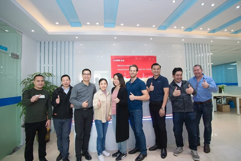
Metal and Plastic Machining Expertise
NOBLE works on machining for both metal and plastic. That focus is important when you need a robot sensor mount that keeps tight tolerances. The team handles aluminum, stainless steel, and engineering plastics such as PEEK and Delrin. Every material has its own problems. NOBLE’s machinists know how to deal with all of them.
Their manufacturing skills cover the whole range of processes. You get CNC milling, turning, drilling, and tapping all in one place. That means fewer handoffs and less chance for mistakes. For robotic sensor-mounted parts, this joined-up approach keeps quality steady from the first cut to the last check.
Certifications and Quality Standards
Quality is not just a saying at NOBLE. The company has ISO 9001:2015 and ISO 13485:2016 certifications. ISO 9001:2015 covers general quality management. ISO 13485:2016 adds the stricter rules needed for medical devices. That second certification tells you something big. NOBLE can meet tough standards for precision and traceability.
So what does this mean for your robot sensor mount project? You get written processes, controlled steps, and a clear record to follow. Every part can be tracked back through production. If something goes wrong, the team can find the main cause fast. That level of control keeps your mounting faces flat and your hole positions correct.
Full-Service Design to Assembly
NOBLE does more than just production. The company offers a full range of services from design to assembly. You can bring a rough idea and leave with a finished part. The team helps with design for manufacturability, material selection, and prototype validation. They also take care of assembly and final inspection.
This end-to-end support saves you time and lowers risk. You do not need to work with five different vendors. One partner manages the whole process. For sensor-mounted parts, that continuity protects your tolerances at every step. From a practical view, fewer handoffs mean fewer chances for errors to slip in.
The team at NOBLE knows that a robot sensor mount is a precision component. They treat it that way. Whether you need one prototype or a full production run, they bring the machining know-how and quality systems to get it right. If you want a manufacturing partner who can handle the whole journey, NOBLE is ready to help.
Precision, material choice, tolerance control, and process optimization shape every good robot sensor mount. A mount is not something you add later. It is a precision part that decides if your robot sees the world clearly or fights constant drift. Use the best practices we talked about. Keep mounting faces flat within 0.02 mm. Pick the right alloy or plastic for your environment. Control your tolerances and improve your process from prototype to production.
From a real-world view, the right partner makes this easier. NOBLE brings metal and plastic machining know-how, ISO 9001:2015 and ISO 13485:2016 certifications, and full-service support from design to assembly. Their cnc machining keeps your robot sensor mount accurate across every batch. Ready to build a mount that performs? NOBLE is ready to help.
FAQs of Robot Sensor Mount
Why does flatness matter so much on a robot sensor mount?
A mounting face that is not flat within 0.02 mm will twist the sensor body when screws tighten. That stress changes how the sensor reads the world. A camera or LiDAR unit then points slightly off, and the error grows with distance. Flat faces keep data clean.
How accurate does my measuring equipment need to be?
NIST says your equipment must be four times more accurate than the tolerance you check. For 0.02 mm flatness, you need a maximum permissible error of 0.005 mm or better. That effectively means a CMM. Calipers cannot do it.
Which material works best for a robot sensor mount?
It depends on your environment. Aluminum 6061 offers a great strength-to-weight ratio for mobile robots. Stainless steel 316 handles salt water and chemicals. PEEK and Delrin damp vibrations and insulate electrically. Carbon fiber is stiff and light but costly and hard to machine.
Can I use split lock washers on my mount?
No. Split lock washers lose all tension within 100 cycles, and NASA rejects them. Nord-Lock wedge washers pass the Junker test at 14g for over 2,000 cycles. They keep roughly 100% of their tension after 1,000 cycles. Vibration will not loosen them.
Why is 5-axis cnc machining better for sensor mounts?
A 5-axis mill cuts angled holes and locating bores in one setup. That avoids stack-up error from multiple setups. Five-axis work holds angled hole positions to ±0.008 mm on aluminum. A 3-axis multi-setup approach lands at ±0.03 mm minimum. One setup also saves time.
How do I stop cables from ruining my sensor signal?
Route power and signal cables at least 50 mm apart. Cross them at 90° angles when they must meet. Use individually shielded pairs for encoder signals. Pick braided shields with 85% or more coverage. Terminate shields at both ends so they do not act like antennas.
What causes calibration drift over time?
Heat is a big cause. A robot arm running all day gets warm, and metal grows. Aluminum expands more than stainless steel. Pre-stretched T651 temper lowers peak internal stresses to under ±15 MPa, which improves stability. Loose fasteners and cable shield wear also drive drift.
When should I move from prototyping to production?
Move forward once your prototype passes validation. CNC machined plastic like Delrin holds ±0.05 mm or better, so it tests mating features well before metal runs. Then scale up with automated pallets and statistical process control. That keeps CpK above 1.33 across thousands of parts.