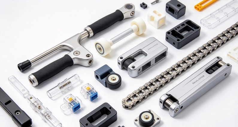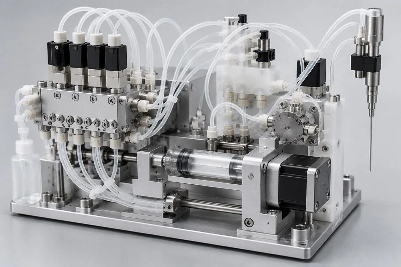
Building a reliable medical device starts with a hard truth. Your entire system depends on how precise its IVD fluid handling components are. Success doesn’t come from picking materials first and then figuring out production later. You need a connected process from the very start. So here’s the question: How do you design IVD fluid handling components that work well, are easy to produce, and stay affordable in large volumes? This guide walks through the key choices for your medical diagnostic device. We’ll cover selecting the right polymer for your medical application. We’ll also discuss optimizing the medical tooling for manufacturing. The real secret is bringing your production partner in early. That collaboration prevents costly redesigns and delays.
Material Selection Criteria for IVD Fluid Handling Components
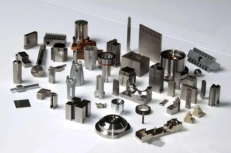
Picking the right material for IVD fluid handling parts means juggling three needs at once. Your medical device needs clear materials for detection systems. You need stable dimensions so parts fit together precisely. You also need materials that resist harsh chemicals used in tests. The polymer you choose affects all three. Trade-offs happen in every medical system. A clear material might bend during molding. Another that resists chemicals might block too much light. The trick is knowing which features matter most for your IVD use. Each part’s job decides which feature comes first. Get this balance wrong, and you will face redesigns later.
Optical Clarity and Dimensional Stability
Requirements for Optical Detection
Many IVD tests need light to pass through the part. Cuvettes and cartridges need clear windows for absorbance or fluorescence readings. The material must let certain light wavelengths through without changing the signal. PMMA is very clear but blocks some UV light. COC and COP materials work well because they let a wide range of light pass. Polycarbonate also works but may turn yellow over time. Your choice depends on how your IVD medical device detects results. This matters most for cuvettes used in absorbance tests during clinical work. Different detection methods need different levels of clarity. The right polymer for windows directly affects how sensitive and repeatable the test is.
Wall thickness also plays a big role. Thicker sections scatter more light and weaken the signal. That hurts sensitivity for samples with low concentration. For small-volume detection, you want thin, even walls. But thin walls are harder to fill during molding. This trade-off needs early input from your manufacturing team. A good manufacturing partner helps you balance optical performance with how easy the part is to mold.
Managing Tolerances and Warpage
Precision matters a lot in IVD instruments. Small leaks ruin an entire test. The material’s shrinkage rate decides how well you can hold tight tolerances. Semi-crystalline polymers like polypropylene shrink more than amorphous ones like polystyrene. That directly changes final dimensions. Your medical device standards demand careful control here.
Warpage happens when part sections cool at different speeds. Uneven wall thickness makes warpage worse. Sharp corners add to the problem. Keeping wall thickness even helps reduce these issues. Draft angles help parts come out of the mold. Without them, parts bend or break. Proper gate placement also lowers internal stress and keeps parts flat. Your specification must account for how the material behaves as it cools. The design should include shrinkage allowances for each material type. Your design should also consider how much the polymer expands with heat. Every medical device application needs this level of care.
Chemical Compatibility and Biocompatibility
Resistance to Assay Reagents
IVD consumables touch many chemicals every day. Buffers, enzymes, and detergents flow through the channels that carry liquids. The material must resist breaking down. Swelling or cracking ruins results. Leaching contaminates the sample too. This matters for every part in the system.
For strong chemicals, standard polymers are not enough. High-performance polymers step in here. PEEK resists strong acids and bases. PVDF handles harsh solvents. These materials cost more but provide the chemical resistance some IVD tests need. Your medical device’s accuracy depends on this choice. Another IVD consumable type might need different properties. Evaluate each part separately based on what it touches. Always test material compatibility with your specific reagents before finalizing the design. This step can save major time and cost later in the project.
Minimizing Protein Binding and Leachables
Proteins in biological samples stick to surfaces. That is protein binding. It lowers the amount of analyte available for detection. It also causes carryover between tests. Pick materials with low binding properties. COC and COP work well. Polypropylene works fairly well too. Some need surface treatments. Your cartridges must meet these same standards for reliable results. Plasma treatments or special coatings can greatly reduce protein sticking. Surface energy plays a big role in how proteins interact with the plastic. The goal is to keep samples intact and ensure consistent results across every run.
Leachables are another concern during development. Small molecules move from plastic into the sample. These interfere with the test chemistry. Medical device rules require extractables testing for leachables. Every medical component must meet these standards for compliance. This matters especially for IVD products going through regulatory review. A third IVD consumable type adds complexity to the selection process. Your medical team must validate material choices thoroughly. This medical device application demands careful attention.
Common Polymers Used in IVD Fluid Handling Components

Real-world IVD systems often use a few main common plastics. Each one always brings its own unique strengths and weaknesses. Your choice affects everything from optical clarity to production cost. Let’s look at the most common options and see where each one shines.
Polypropylene (PP) and Polystyrene (PS)
Polypropylene dominates the IVD for a very good reason. It resists most common reagents, handles autoclaving heat, and costs very little. Many diagnostic cartridges use PP for their main body because it works well enough against buffers and mild detergents. The material also offers decent chemical resistance for routine tests. But PP has a downside. It turns cloudy or see-through, which blocks detection light paths. That’s why you rarely see PP in cuvettes or detection windows. Its semi-crystalline nature also means more shrinkage during cooling, which makes tight tolerances harder to hold.
Polystyrene works the opposite way. It’s crystal clear and cheap, making it perfect for optical parts. Many cuvettes and test plates use PS because light passes through easily. The material also molds with excellent dimensional stability. However, PS cracks under chemical stress. Strong solvents or harsh reagents will destroy it quickly. So PS works best for simple tests with gentle chemistry. Many medical consumables use PS for sample wells and viewing windows where clarity matters more than chemical toughness.
PMMA, Polycarbonate (PC), and Cyclic Olefin Copolymers (COC/COP)
PMMA offers very good clarity and weather resistance. It lets light through well across the visible range. But PMMA soaks up water and can bend in damp air. It also breaks easily, so thin walls may crack when handled. Polycarbonate is tough. It can handle rough use and resist bumps. PC also takes higher heat than PS or PMMA. But PC turns yellow over time in UV light, which hurts optical performance in detection.
Cyclic olefin copolymers and polymers, often called COC or COP, have become favorites for advanced IVD fluid handling parts. These materials mix excellent clarity with low protein sticking and few leachables. They also resist water much better than PMMA. Many diagnostic cartridges now use COC for tiny channels and optical windows. The material flows well during molding, which helps make fine features. COC costs more than PP or PS, but its performance is worth the price for hard jobs. Medical device designers often pick COC when they need both optical accuracy and chemical stability.
High-Performance Polymers (PEEK, PVDF)
Some IVD tests use very strong chemicals. Normal plastics simply cannot survive contact with strong acids, bases, or certain organic solvents. That’s where high-performance polymers come in. PEEK stands up to almost every chemical you can throw at it. It also keeps its physical properties at high heat. This makes PEEK perfect for fittings, valves, and pump parts that face harsh reagents again and again. The downside? PEEK costs a lot more than common plastics and needs higher processing heat during making.
PVDF offers similar chemical resistance with a different property set. It handles halogens and strong oxidizers very well. Many fluid handling systems use PVDF for tubing and manifold parts that carry harsh media. The material also has low extractables, which matters for sensitive tests. Both PEEK and PVDF bring real benefits, but they need careful mold design and process control. You’ll pay more per part, yet the reliability gains often beat the added cost for critical medical uses.
Design for Manufacturing (DFM) Rules for IVD Fluid Handling Components
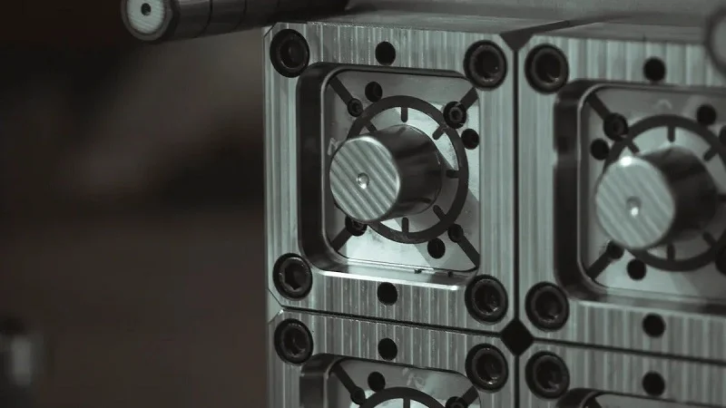
Good design rules keep your project moving forward. They connect what you draw on paper to what actually comes out of the mold. For IVD fluid handling components, these rules matter even more. Your parts carry tiny volumes of liquid through narrow paths. A small flaw in wall thickness or gate placement turns into a failed test. Medical device design demands precision at every step. Regulatory reviewers look closely at how you control your manufacturing process. They want proof that your parts stay consistent across millions of units. So let’s walk through the core DFM rules that keep your project on track.
Optimizing Wall Thickness and Draft Angles
Wall thickness drives everything in injection molding. Uniform walls let plastic flow evenly through the cavity. They also help the part cool at the same rate. When one section cools faster than another, the part warps. Thin walls fill fast but cool too quickly. Thick walls take longer and create sink marks. For diagnostic cartridges, you want walls between 1 mm and 2 mm where possible. That range balances strength with moldability. But microfluidic channels need much thinner sections. Those fine features require careful flow analysis before you cut steel.
Draft angles are equally important. They let the finished part release from the mold without sticking. Without enough draft, ejection forces scratch or bend the part. The right angle depends on your surface finish. Here’s a quick reference for polystyrene parts:
| Surface Finish | Recommended Draft Angle | Notes |
| High-gloss (polished) | 1° – 2° | Prevents marks; balances aesthetics and function |
A smooth finish needs only 1 to 2 degrees of draft. Textured surfaces need more, often 3 to 5 degrees per side. Your mold designer should confirm the angle during the design review. Getting this wrong means costly mold rework later.
Strategic Gate Placement and Weld Line Management
The gate is where molten plastic enters the mold cavity. Its location controls how the material flows. It also determines where weld lines form. Weld lines happen when two flow fronts meet and fuse together. These lines weaken the part. They also create visible marks on the surface. For IVD consumables, weld lines near fluid channels are dangerous. They can crack under pressure and cause leaks.
Place gates where the flow path stays simple. Avoid placing them near thin walls or sharp corners. A single gate works best for small parts. Larger parts may need multiple gates, but each one adds a weld line. Your team should map out every weld line during the design phase. Ask yourself: does this line sit near a sealing surface? Does it cross a detection window? If yes, move the gate or adjust the flow pattern.
Gate location also affects aesthetics. Visible gate marks on optical surfaces ruin clarity. Put gates on hidden faces or non-critical areas. This keeps your detection windows clean and your parts looking professional. Remember that every change to gate placement changes the flow dynamics. Run mold flow simulations early to catch problems before tooling starts.
Accounting for Material Shrinkage and Tolerance Stack-Up
Every polymer shrinks as it cools. The shrinkage rate varies by material. Semi-crystalline plastics like polypropylene shrink more than amorphous ones like COC. Your design specification must include shrinkage allowances for each material. Otherwise, your finished part won’t match the drawing.
Tolerance stack-up adds another layer of complexity. Each feature on your part has its own tolerance. When multiple features interact, the errors add up. For press-fit connections or snap joints, this stacking can break the assembly. Your engineering team should calculate the worst-case scenario. Will the parts still fit if every dimension sits at its limit? If not, tighten the critical tolerances or redesign the joint.
COC materials offer excellent dimensional control for microfluidic work. Real production data shows what’s possible:
| Parameter | Achieved Tolerance | Process Capability (Cpk) |
| Microfluidic channel width | 100 μm ± 5 μm | 1.67 |
| Channel depth | ±3 μm | Exceeded minimum 1.33 |
These numbers show that tight tolerances are achievable. But they require careful process control and validated tooling. A Cpk of 1.67 means the process stays well within limits. Most medical device standards expect a minimum Cpk of 1.33 for critical features. Your manufacturing partner should provide capability data during validation. This testing proves your parts meet specification every time.
From a practical perspective, start with realistic tolerances. Don’t specify ±5 μm on every dimension. Only critical features need that level of control. Everything else can use standard tolerances. This approach keeps your mold cost down and your production yield high. Your component design should reflect this balance between precision and practicality.
The broader lesson connects back to medical device design. Regulatory bodies want evidence that your manufacturing process stays in control. DFM rules give you that evidence. They reduce variation, prevent defects, and document your reasoning. When you follow these rules, your IVD fluid handling components perform reliably. Your cartridges work the same way on day one and day one thousand. That consistency builds trust with clinicians and patients alike.
Cost Optimization and Partnering for IVD Fluidics

Cost drives every choice in medical product development. You can have the best design on paper. But if each part costs too much, the project stalls. Smart savings start at the design stage. Waiting until production begins means you missed the biggest savings.
Strategies for Reducing Part Cost
Part Consolidation and Design Simplification
Every feature on your part adds cost to the mold. Think about undercuts. Each one needs a side-action mechanism. Those sliders or lifters add $1,000 to $2,000 or more to the mold cost. They also slow down cycle time and create maintenance risks.
The fix costs nothing at the design stage. You can redesign the parting surface. You can adjust draft angles. You can replace mechanical actions with pass-through cores. These changes remove undercuts without hurting function.
Design-for-manufacturability changes can cut per-part costs by 30 to 50 percent. The earlier you make these changes, the bigger the savings. Once the mold is cut, changes become far more expensive.
For internal features, collapsible cores offer another path. They form the feature at full size during injection. Then they pull inward for ejection. This removes side actions in many applications. It reduces mold footprint, improves repeatability, and shortens cycle times. The medical industry uses this method for consumables where tight tolerances matter.
Your part shape also affects material usage. Simpler shapes fill faster and use less resin. That cuts per-part material cost directly. Every gram removed adds up across millions of medical consumables.
The Value of Outsourcing vs. In-House Production
Many medical teams debate building manufacturing capacity in-house or partnering with a specialist. Each path has trade-offs.
In-house production gives you direct control. You manage the schedule and quality-check yourself. But it requires major capital investment. You need cleanroom space, molding machines, and skilled operators. For low to medium volumes, that investment is hard to justify.
Outsourcing shifts the capital burden to the partner. You pay for parts, not machines. Your team focuses on core activities like design verification. A good partner brings experience from similar medical projects. They optimize cycle times and yield rates. They also handle regulatory paperwork that medical production requires.
For diagnostic cartridges and consumables made in high volumes, outsourcing often wins. The partner’s scale drives down per-unit cost. They provide production backup. If one machine goes down, they shift to another. You avoid the downtime risk of an internal line.
The Importance of Early Manufacturing Partner Involvement
Design for Assembly (DFA) and Value Engineering
Bringing your manufacturing partner in early changes everything. Instead of handing them a finished design, you work together from the start. This is where DFA and value engineering create real savings.
Design for Assembly looks at how parts fit together. Does your cartridge need separate pieces? Can you combine two parts into one? Every joint adds assembly time and inspection cost. Reducing those steps cuts labor and lowers defect rates.
Value engineering examines function versus cost. The partner asks: does this feature serve a purpose? Can we get the same result with simpler geometry? A small change in a channel might reduce cycle time without affecting performance.
Your specification defines critical dimensions. Those need tight control. Everything else can use standard tolerances. A partner who understands your medical device design helps separate must-haves from nice-to-haves.
The holistic approach treats your system as a whole. Instead of optimizing each part alone, you optimize the assembly. This might mean adjusting a valve port so the tubing route shortens. It might mean changing a connector design for faster installation. Small changes add up into large savings. Every medical device team should use this approach for their next project.
Early involvement also helps with material selection for cost. A partner who molds many types of medical parts knows which resins flow well. They know which ones drive up cycle time. They suggest alternatives that meet your needs at a lower price. That guidance is hard to find when you work alone. The cost savings from early involvement go beyond tooling. They affect yield rates, assembly time, and regulatory risk for every device you build.
NOBLE’s Capabilities for Manufacturing IVD Fluid Handling Components

Working with NOBLE on your IVD fluid handling components means getting a partner who sees the whole picture. We join your team from the very first design meeting. We spot problems before they turn into expensive fixes. This method saves you time and reduces stress during your medical product development.
Precision Machining and Injection Molding Expertise
From Prototype to High-Volume Production
Every good product starts with a prototype. NOBLE uses CNC machining to create exact parts for your early tests. These machined parts let you check your design before spending money on production tooling. You can run real assays. You can test how parts fit and work. Changes at this point cost much less than after tooling starts.
Once the design is ready, we move to injection molding. Our engineers fine-tune every process detail. They look at gate placement, cooling channels, and cycle times. The outcome is steady parts that meet your spec every time. This dependability is key for medical items like cartridges and cuvettes.
For large runs, NOBLE uses multi-cavity tools. These make thousands of parts each hour. Every cavity stays the same. Every part matches the next one. We watch conditions live to catch drift before it harms quality. This control matters for medical uses where consistency is critical. This level of accuracy is what medical device designers expect.
We also offer bridge tooling for smaller runs. Maybe you need parts for clinical trials. Bridge tools give production-quality parts without a full tooling investment. This keeps your schedule moving forward.
Certified Quality Management Systems
ISO 9001:2015 and ISO 13485:2016 Compliance
Quality forms the base of medical manufacturing. NOBLE works under two certified systems. ISO 9001:2015 covers our general processes. ISO 13485:2016 adds the rules for making medical devices.
These certifications mean your parts get made inside a controlled system. Every step has a written procedure. Every worker follows clear instructions. Every problem gets looked into. This discipline keeps production steady.
Validation is a key part of our system. We validate every tool and every process before production. Process validation includes IQ, OQ, and PQ steps. These steps prove the process can make parts that meet spec every time.
Internal audits check our systems on a regular basis. Outside auditors review us each year. This oversight makes sure we never slip from medical standards.
For your medical device, this means documented quality. Your audits become simpler. Your submissions become stronger.
Integrated Services from Design to Assembly
NOBLE does more than mold parts. We help design them, make them, and put them together. This combined approach cuts down on handoffs and improves communication.
Our design engineers work with your team on part shape. We suggest changes that improve molding without hurting function. We study flow patterns to avoid weak spots in critical areas. We adjust wall thickness for even cooling.
When parts leave the press, we offer extra steps. Ultrasonic welding joins parts into assemblies. Laser marking adds labels. Cleaning and packaging get parts ready to ship.
Our cleanroom assembly line meets requirements for medical items. Operators follow detailed work steps. Each assembly gets checked before leaving the line.
Testing services confirm your device works as it should. We run leak tests on fluid paths. We measure optical clarity on detection windows. All data gets recorded and shared.
This full-service ability means one partner handles your entire production. You manage fewer vendors. You have shorter supply chains. You gain better control over quality and timing.
From your first prototype to your millionth part, NOBLE delivers. We invest in the tools and people to make medical parts you can trust. Your product performance depends on every detail. We make sure those details are correct.
Building IVD fluid handling components works best when teams work together from day one. Know your materials first. Know your optical needs, chemical exposure, and tolerance needs. Bring your manufacturing partner in early. Their tooling know-how stops costly surprises. Their process control keeps every medical device steady. This teamwork cuts redesigns and speeds up your timeline. Every medical consumable gains from this approach. Your medical team feels sure when production matches design. Your medical device reaches patients faster. Skip the isolated workflow. Pick a partner who helps with prototyping, molding, and final assembly. Ask about their validation protocols and testing abilities. The right partner turns component problems into reliable products. Your next project deserves this connected path from concept to finished cartridge.
FAQ of IVD Fluid Handling Components
Which polymer offers the best optical clarity for detection windows?
Cyclic olefin copolymers (COC/COP) let light pass through a broad range of wavelengths. They also absorb less water than PMMA. For most medical diagnostic systems, COC gives the best mix of clarity and stability. Polycarbonate also works but may turn yellow over time in medical instruments.
How do I stop proteins from sticking to my channels?
Pick materials that resist binding. COC and COP perform well here. Polypropylene works fairly well for many medical assays. Surface treatments like plasma coating can also lower protein adhesion. Always test your specific reagents with your chosen material before you finalize the design for your medical device.
What wall thickness should I use for my cartridge?
Try for 1 to 2 mm when you can. This range balances strength with how well the part molds. Microfluidic channels need thinner sections, often below 0.5 mm. Those fine features require careful flow analysis before cutting the mold. Your manufacturing partner should run simulations early to spot filling problems.
When should I bring my production partner into the project?
Bring them in during the design phase, not after. Early teamwork prevents costly mold rework. A partner who knows medical device requirements can suggest material changes and geometry tweaks that save money. Waiting until tooling starts means you lose the biggest savings opportunities for your medical product.
How do weld lines affect my part’s performance?
Weld lines form where two flow fronts meet. They weaken the part and leave visible marks. Near fluid channels, they create a leak risk. Your mold designer should map every weld line during the design review. Move gates or adjust flow patterns if weld lines cross critical sealing surfaces in your medical cartridge.
What tolerances can I realistically hold for microfluidic features?
Channel widths around 100 microns with ±5 micron tolerance are possible. Process capability (Cpk) of 1.67 is achievable with careful control. Most medical device standards expect a minimum Cpk of 1.33 for critical features. Only specify tight tolerances where function demands them for your medical application.
How do I choose between COC and polycarbonate?
COC offers better clarity, lower protein binding, and fewer leachables. Polycarbonate provides higher impact strength and heat resistance. For medical cartridges with optical detection, COC usually wins. For parts that face rough handling, polycarbonate may serve better. Think about what your specific application needs.
What certifications should my manufacturing partner hold?
Look for ISO 9001:2015 and ISO 13485:2016 certification. These ensure controlled processes and proper documentation. Ask about their validation protocols. Process validation with IQ, OQ, and PQ steps proves they can make parts that meet spec consistently. This documentation strengthens your regulatory submissions.