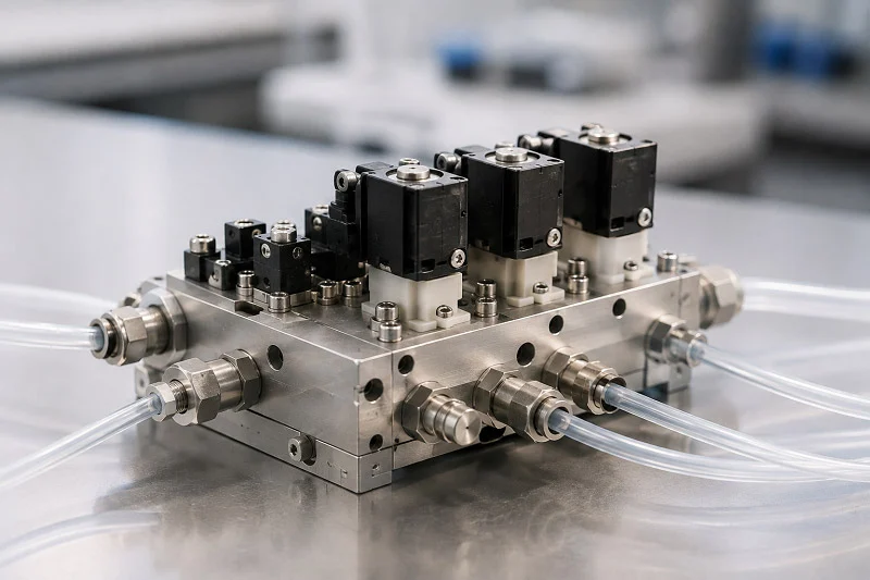
Choosing the right hydraulic valve blocks shapes your whole system’s success. That one choice affects performance, cost, and long-term reliability. The hydraulic market shows real growth here—reports put the 2024 global market size for these parts at about 2.2 billion USD.
| Reported Source | 2024 Market Size (USD Million) |
| Report Attribute Table | 2190.4 |
| FAQ Section | 2304.3 |
Every hydraulic job needs different trade-offs. Some focus on cutting weight. Others need to handle extreme pressure. Your system’s environment, duty cycle, and maintenance schedule all affect the best fluidic valve block design. Knowing how hydraulic valve blocks work in real conditions helps you avoid expensive redesigns. Smart material picks and precise manufacturing turn a simple valve into a reliable workhorse. This guide walks through those choices step by step.
Defining the Fluidic Valve Block and Its Core Function
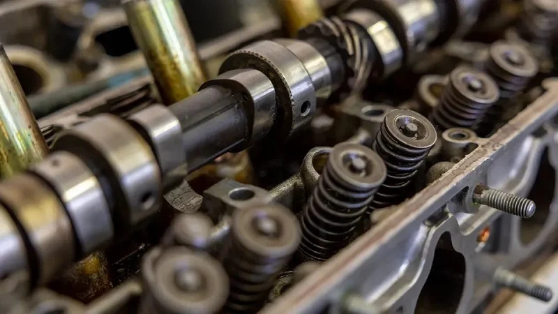
Imagine a fluidic valve block as the traffic cop for your system. It handles the hard tasks of moving fluid, controlling pressure, and managing actuators, all in one neat package. The main jobs of hydraulic valve blocks are simple: they control where fluid goes, how much pressure it has, and when it arrives. Without this central hub, your system would need many separate pipes and fittings. That adds weight, cost, and spots where leaks can start. Hydraulic valve blocks help keep these systems running well.
The Role of a Manifold in Fluid Power Systems
A manifold is the base of any modern fluid power system. It holds parts in place and links them through internal passages. This design reduces outside tubing. The whole setup stays more compact. Hydraulic valve blocks act as the main support, turning a mess of hoses into a neat, organized unit. The system gains from less complexity.
Directing Flow Paths and Regulating Pressure
The first job of hydraulic valve blocks is to send fluid where it needs to go. Different internal parts either block or let fluid flow. Some release pressure when needed. Others stop backflow that could hurt parts. Automated choices add control for complex jobs. All these parts work together inside the block.
Pressure control is just as important. Pressure control parts keep things in check. Reducing parts keep a set level downstream. Relief paths drain extra fluid back to the tank when pressure gets too high. Sequencing parts wait until a key pressure is reached, then send flow somewhere else. Some systems use pilot-operated types for even more advanced control. This stops leaks and burst pipes.
Consolidating Components to Reduce Leak Points
Here is a simple truth about hydraulic systems: every leak point can cause a failure. Every fitting, every joint, every connection can break over time. By putting many parts into one block, you greatly cut the number of outside connections. That means fewer spots for fluid to leak out. Hydraulic valve blocks also give structural support with their aluminum or cast iron body. Pipe joints handle input, return, and drainage neatly. The result is a system that stays reliable longer and needs less upkeep. Good performance depends on smart consolidation.
Key Performance Metrics for Valve Blocks
Not all hydraulic valve blocks work the same. You need to check a few key numbers. Flow rate, pressure rating, leakage tolerance, and expected cycle life all matter. The performance of hydraulic systems depends on picking the right numbers for each job. Tracking these numbers helps improve overall efficiency.
Flow Rate Capacity and Pressure Ratings
Flow rate tells you how much fluid the block can move. For a 25 L/min top flow need, pick a part rated 30 to 40 L/min. That 25 to 50 percent extra above the top gives you better control at low settings. The pressure rating matters just as much. For a 40 bar working pressure system, pick parts rated at least 1.5 times that, or 60 bar. Burst ratings should be more than 3 times working pressure. Different types handle different ranges. Low flow control parts handle up to 50 ln/min at 64 to 200 bar. High-pressure control parts can manage up to 100 ln/min at 400 to 700 bar. Parts for low pressure drop move up to 1000 ln/min.
Leakage Tolerance and Cycle Life Expectations
Leakage tolerance depends on your use. The system powering a factory press can handle some internal leakage. A medical device or aerospace part cannot. The valve block design, seal materials, and surface finish all help control it. Cycle life counts how many times the inside mechanism can open and close before it wears out. Higher-quality hydraulic valve blocks use hardened spools and tight tolerances to make this life longer. Expect thousands to millions of cycles depending on the design and how it runs. Hydraulic systems work best when the block fits the working environment. Good efficiency and strong performance depend on getting these details right.
Materials for a Fluidic Valve Block
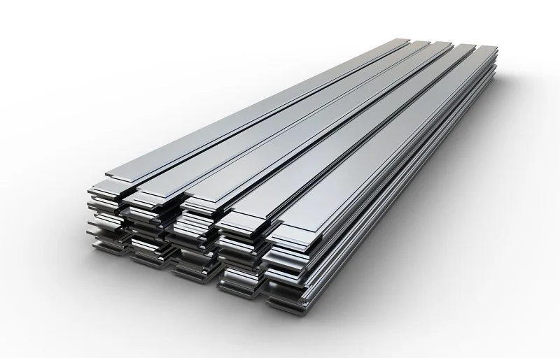
Choosing the right material for a fluidic valve block is half the engineering battle. The material determines weight, strength, cost, and how the block handles pressure. Different hydraulic jobs demand different raw materials. Some systems ride on mobile equipment where every pound matters. Others sit in factories where durability beats weight savings. Understanding these trade-offs helps you match the block to the job.
Aluminum Alloys: The Industry Standard
Aluminum dominates the world of hydraulic valve blocks for good reason. It offers a strength-to-weight ratio that steel simply cannot match. A typical aluminum block weighs about one-third of a steel equivalent. That weight saving matters enormously in mobile applications like excavators, forklifts, and agricultural equipment. Less weight means better fuel efficiency and easier installation.
Aluminum also conducts heat well. Hydraulic systems generate heat as fluid moves through tight passages. Aluminum pulls that heat away from critical seals and valves, extending their service life. The material resists corrosion naturally, forming a thin oxide layer that protects against moisture and many chemicals.
| Property | Value Range |
| Tensile Strength | 185 – 250 MPa (27 – 36 ksi) |
| Yield Strength | 125 – 185 MPa (18 – 27 ksi) |
These numbers show why aluminum handles most hydraulic applications with confidence. The yield strength tells you when the material starts to deform permanently. For a block rated at 250 bar working pressure, aluminum’s yield strength provides a comfortable safety margin.
Not all aluminum alloys perform the same. The alloy choice changes machinability, strength, and environmental compliance.
- Alloy 6042: Used in pneumatic and hydraulic manifolds and valve blocks, offering improved machinability and RoHS compliance.
- Alloy 6061: Commonly used for hydraulic valve bodies, valves, and valve parts, known for good strength-to-weight ratio and corrosion resistance.
- Alloy 6262: Specifically developed for machining, used in hydraulic valve blocks, but contains lead and does not meet RoHS/ELV requirements.
The RoHS distinction matters more every year. Regulations in Europe and elsewhere restrict hazardous substances. If your product ships internationally, choose 6042 or 6061 to stay compliant. The machinability of these alloys also affects production cost. Better machinability means faster cycle times and less tool wear.
Steel and Stainless Steel for High-Pressure Systems
Some hydraulic applications push far beyond what aluminum can handle. Extreme pressures, harsh chemicals, and abrasive environments demand steel. Carbon steel and alloy steel bring serious strength to the table. A carbon steel block body can handle ratings up to PN500 (7250 PSI). That level of pressure would deform aluminum quickly.
Steel also resists fatigue better than aluminum. Repeated pressure cycles create stress inside the block. Steel handles millions of cycles without cracking. This durability makes steel the standard for industrial presses, mining equipment, and offshore drilling systems.
Stainless steel adds corrosion resistance to the mix. Saltwater, chemical washdowns, and humid environments attack carbon steel over time. Stainless steel contains chromium, which forms a protective layer against rust. This makes it ideal for marine hydraulics, food processing equipment, and pharmaceutical manufacturing.
The trade-off comes with weight and cost. Steel blocks weigh significantly more than aluminum. They also cost more to machine because the material is harder on cutting tools. For stationary equipment where weight does not matter, steel makes sense. For mobile applications, the weight penalty often rules it out.
Alternative Materials: Brass, Plastics, and Composites
Beyond the big two, several other raw materials serve specialized hydraulic needs. Brass offers a cost-effective option for low-pressure systems. It machines easily, resists corrosion, and handles moderate pressures without breaking the bank. Many pneumatic systems and low-pressure hydraulic circuits use brass blocks successfully.
Engineered plastics like PEEK open up entirely new possibilities. These materials resist chemicals that would destroy metal blocks. PEEK stands up to acids, bases, hydrocarbons, and other corrosive media without needing protective coatings. That chemical resistance eliminates secondary sealing systems, simplifying valve design and reducing manufacturing complexity.
Chemical compatibility considerations reveal that while PTFE maintains broader resistance across aggressive media, PEEK demonstrates adequate compatibility with most industrial fluids while offering superior mechanical performance. The trade-off between chemical inertness and thermal-mechanical stability becomes the decisive factor in material selection for applications exceeding 200°C.
PEEK also meets UL94 V-0 flame retardant standards. That makes it suitable for applications requiring both chemical inertness and safety. The material weighs far less than metal, which helps in aerospace and portable equipment.
Composites blend fibers with polymer matrices to create custom properties. They offer high strength with very low weight. However, composites cost more and require specialized manufacturing processes. Most hydraulic valve blocks stick with aluminum or steel unless a specific requirement forces a different choice.
The selection of raw materials ultimately comes down to your system’s demands. Pressure rating, weight budget, chemical exposure, and cost all factor into the decision. A knowledgeable manufacturing partner helps navigate these choices. NOBLE, a leading manufacturing partner in China, specializes in material selection and processing. Their expertise spans both metal and plastic fabrication, helping clients move from prototype to mass production with confidence. They understand how each material behaves under real-world hydraulic conditions and can recommend the right option for your specific application.
The casting process also influences material choice. Some alloys cast better than others. Aluminum casts easily, which makes it ideal for high-volume production. Steel requires more complex casting procedures. Understanding these manufacturing constraints early prevents costly redesigns later.
Processes Suitable for Fluidic Valve Block Manufacturing
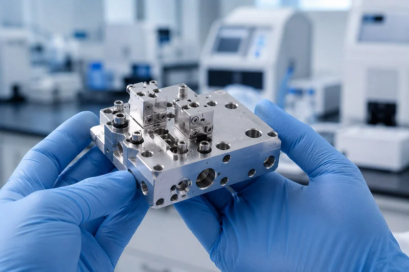
Picking the best material is not enough. You also need the right way to make the part. How you turn raw material into a finished block changes the cost, accuracy, and how well it works. There are three main steps: making the rough shape, cutting it to exact size, and treating the surface. Each step builds on the one before. If you get all three right, your hydraulic system will work as planned.
Casting and Forging: Creating the Blank
Every hydraulic valve block starts as a blank. A blank is the rough shape of the final part. Two main ways to make these blanks are casting and forging. Each one fits different production amounts and performance needs.
Die casting is the top choice for making many parts quickly. Hot aluminum gets pushed into a steel mold under high pressure. The result is a shape that is close to the final part. That means less cutting work later. Die casting gives you a smoother surface and more exact sizes than forging. For valve block blanks, that means the inside channels come out cleaner. Less fluid turbulence means better performance. The table below shows the main differences.
| Process | Surface Finish (RMS) | Dimensional Tolerance |
| Die Casting | Smoother than forging | Tighter than forging |
| Forging | 125 – 250 microinches | ±0.020 inches |
Forging works a different way. It uses heat and pressure to shape the metal. The metal’s grain structure lines up with the part’s shape. That makes the block stronger. Forging is great for high-pressure hydraulic systems where strength matters more than surface smoothness. The trade-off is clear. Forged blanks need more cutting to reach the same accuracy as die-cast ones. They also cost more per part when making many.
The choice between these two methods depends on how many parts you need and how strong they must be. Die casting works well for thousands of parts. Forging fits lower amounts or very high-pressure jobs. Many makers use both methods depending on the job. Knowing these options helps you pick the right path for your valve casting production.
CNC Machining: Achieving Precision
The blank is just the start. Real accuracy comes from CNC machining. This process turns a rough casting or forging into a finished hydraulic valve block with exact sizes. Without it, the inside channels would not line up right. The whole system would leak or fail.
CNC machining centers use spinning cutting tools to remove material. They mill flat surfaces, drill holes, and make complex inside channels. These channels are the veins of the hydraulic system. They move fluid from one port to another with little resistance. How accurate these channels are decides how well the block works.
Typical tolerances for hydraulic valve blocks range from ±0.001 to ±0.005 inches on key features. Bore sizes for valve spools often need even tighter control. Surface finishes on sealing areas must be smooth enough to stop leaks. A good CNC machine can hold these numbers across hundreds or thousands of parts.
Modern machining centers also handle complex shapes. Engineers can design inside channels that lower pressure drop. They can place ports exactly where needed. The machine follows the CAD model exactly. No guessing, no hand adjustments.
For high-volume production, several machining centers work at the same time. One machine roughs out the part. Another finishes the key surfaces. A third drills the deep holes for fluid paths. This split of work keeps cycle times short and quality steady. Each machine focuses on one type of job. That approach cuts changeover time and boosts accuracy.
Post-Machining and Surface Treatment
Machining leaves behind sharp edges and metal burrs. Those burrs must go before the block goes into service. A loose burr in a hydraulic system can harm seals, clog valves, and cause big failures. Deburring is not optional. It is a key step in the making process.
The first step is deburring. Workers use hand tools, abrasive brushes, or heat methods to remove every sharp edge. Automated deburring machines handle large amounts. For complex inside channels, special tools reach every corner. The goal is a block with no sharp edges anywhere.
Next comes cleaning. Machining fluids, metal chips, and dirt must be removed completely. Ultrasonic cleaning tanks use high-frequency sound waves to scrub every surface. High-pressure water jets blast away tough dirt. The goal is a perfectly clean block ready for coating or assembly.
Surface treatments add the final layer of protection. Anodizing is common for aluminum blocks. It creates a hard, rust-resistant oxide layer on the surface. The anodized coating also improves wear resistance. For steel blocks, plating with zinc or nickel provides rust protection. Passivation treats stainless steel to boost its natural oxide layer.
Some jobs need special coatings. Hard anodizing for extreme wear. Electroless nickel for chemical resistance. PTFE coating for low friction. The right treatment depends on the working environment. A skilled manufacturing partner can help you choose.
Quality control runs through every step. Size checks confirm the block meets the print. Pressure tests verify the block can handle working pressure without leaking. Flow tests measure how well the inside channels perform. Any block that fails these tests gets rejected.
NOBLE brings all these skills together under one roof. Their manufacturing know-how covers both metal and plastic work. They handle prototyping, small runs, and full-scale production. Their team understands how each process affects the final part. They can suggest the right casting method, machining plan, and surface treatment for your specific job. That kind of partnership saves time and lowers risk.
Precision Requirements for a Fluidic Valve Block
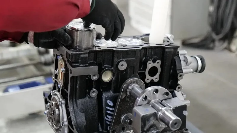
Precision is what makes a hydraulic valve block reliable instead of leaky. The inside shape controls how well seals hold, how smoothly parts move, and how long the system lasts. Small machining mistakes turn into big problems when pressure builds. Getting the numbers right early prevents trouble later.
Critical Tolerances and Geometries
Bore diameter is the most important measurement. The bore holds the spool that guides hydraulic flow. If the bore is too big, fluid slips past the spool and leaks inside. If it is too small, the spool sticks and the valve jams. Typical bore tolerances stay within ±0.001 to ±0.005 inches, based on the job. Systems that run many cycles need the tighter end of that range.
Surface finish matters just as much. Rough surfaces damage seals and let fluid escape. The sealing face on a hydraulic valve block should measure Ra ≤0.8 μm. That smoothness lets O-rings and gaskets fit properly. Metal-to-metal sealing surfaces need the same finish to stop weeping under pressure.
Flatness and parallelism control how the block connects to other parts. A warped mounting surface twists the port pattern and causes internal leaks. Sealing face flatness tolerance should stay at ±0.003–0.005 mm. That tight range ensures even contact across the whole face. For the mounting surface, a flatness tolerance of 0.002 inches (0.0508 mm) over the port pattern area stops distortion that would break the seal.
Parallelism works with flatness. The top and bottom faces of the block must stay parallel. If they drift, the block twists when bolted down. That twist puts stress on the seals and shortens their life. Good machining keeps parallelism within the same range as flatness.
The Role of Metrology in Quality Control
You cannot manage what you cannot measure. Metrology gives you the data to confirm each hydraulic valve block meets its print. Coordinate measuring machines (CMMs) do the heavy lifting. A CMM probes the block at dozens of points and compares the readings to the CAD model. It checks bore diameters, hole positions, flatness, and parallelism in one setup.
CMM data catches problems before parts ship. A bore that drifts out of tolerance gets rejected early. A mounting face that fails flatness gets reworked or scrapped. This testing protects your system from early failure.
Dimensional checks only tell part of the story. Functional testing confirms real-world behavior. Pressure testing fills the block with fluid and holds it at working pressure. The block must hold that pressure without external leaks. Flow testing measures how much fluid moves through each port and checks for internal bypass. Together, these tests confirm the block works as designed.
Valve performance testing ties everything together. It cycles the assembled valve through its full range of motion while checking response time, pressure drop, and leakage. This testing catches issues that dimensional checks miss, like a spool that sticks at temperature or a seal that weeps under vibration.
Every batch of hydraulic valve blocks should pass through the same metrology gauntlet. First-article inspection verifies the setup. In-process checks catch drift early. Final inspection confirms the finished part. This layered approach keeps quality steady across thousands of parts. A manufacturing partner with strong metrology capabilities reduces your risk and delivers blocks that perform reliably in the field.
Key Design Considerations for a Fluidic Valve Block
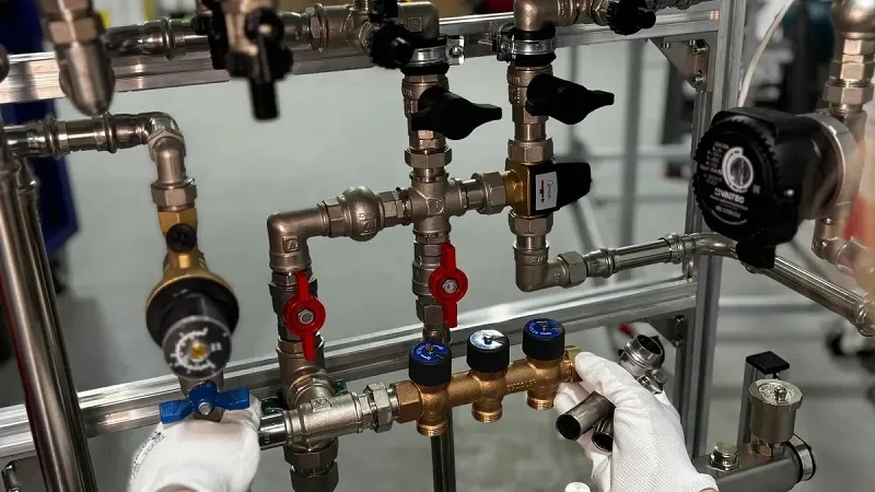
Good design takes planning. Engineers must think about how the block gets made, how heat moves through it, and how it links to the rest of the system. Getting these three areas right keeps a hydraulic system running smoothly instead of causing problems at every step.
Designing for Manufacturability (DFM)
DFM has one simple goal. Make the part easy to build while still doing its job. Every extra cut, tight tolerance, and odd angle adds cost. Smart design lowers that cost.
Start with tolerances. Only surfaces that touch seals or guide spools need the tightest numbers. The rest of the block can be more relaxed. Changing a tolerance from ±0.01mm to ±0.05mm on a non-mating face can cut the cost of that feature in half. That saves real money on every part.
Next, think about tool access. Internal corners need a radius. A good rule is to make that radius at least 1/8th of the cavity depth. That lets the cutter use a shorter, more rigid tool. Less chatter means a better surface finish and longer tool life.
Wall thickness and feature ratios matter too. For metal blocks, keep walls above 0.8mm. For plastic, go above 1.5mm. Hole depth should stay under 10 times the diameter. Feature height should not exceed 4 times the width. These rules prevent vibration, warping, and broken tools. Good hydraulic valve blocks follow these guidelines from the start. The best valve design accounts for manufacturing limits early. Good flow control starts with smart tolerancing.
Thermal Management and Fluid Dynamics
Heat is the enemy of all hydraulic systems. Fluid gets thin when it heats up. Seals wear faster. The whole system loses efficiency. Good valve design manages this heat.
Channel size and shape control how fluid moves. A wider channel drops pressure less. But it also takes up space and adds weight. The trick is finding the balance. Sharp turns create turbulence. Turbulence generates heat. Smooth, gradual bends keep flow steady and cool. The right design helps control the temperature of the fluid.
The block material also plays a role. Aluminum pulls heat away from the fluid. That helps the system stay at a stable temperature. Steel holds heat longer. For high-flow circuits, spreading the channels out helps. More surface area means more heat leaves the fluid.
Flow path optimization is a core part of modern hydraulic valve blocks. Engineers use simulation software to test different channel layouts. They look for spots where flow slows down or speeds up too much. Every improvement in flow means better performance and longer component life. The hydraulic layout must balance efficiency against manufacturing cost. Well-designed hydraulic valve blocks manage heat better. Good hydraulic systems rely on smart flow paths.
Integration with System Components
A valve block does not live alone. It connects to pumps, actuators, and other parts. The interfaces between these parts must match exactly. Standardization makes this possible.
The most common mounting standard is ISO 4401. You might also hear it called NFPA D03, CETOP 3, or NG6. These names all point to the same thing. The standard defines where ports go, what size they are, and where the bolts sit. A block that follows ISO 4401 accepts valves from many different makers. That flexibility saves time and money.
The interface layout for a sub-plate of size 03 follows ISO 4401. This standard also covers CETOP 3 (NG6, D03) and CETOP 5 (NG10, D05) valves. These are the most common patterns in the industry. Using them means your block works with off-the-shelf parts.
Modular hydraulic valve blocks build on this idea. They let you stack functions together without custom machining. Need an extra function? Add another block. This approach cuts design time and makes future changes easier. These systems adapt well when requirements shift. Integrated hydraulic valve blocks take the opposite path. They combine many functions into one custom block. That saves space and weight but locks the design in place. Different systems have different needs.
Both approaches have their place. The key is knowing which fits your system. Standardized ports, seals, and mounting patterns make everything work together. Without them, every connection becomes a custom job. That drives up cost and delays every project. Standardized hydraulic valve blocks connect more easily. Standardized parts give you more control over the final assembly. Reliable hydraulic systems depend on good integration. Integrated hydraulic valve blocks work well for fixed designs. The hydraulic performance improves with smart choices.
Partnering with NOBLE for Your Fluidic Valve Block Needs

Our Comprehensive Manufacturing Capabilities
NOBLE brings together everything you need for hydraulic valve blocks. They work with both metals and plastics. That means one partner handles the whole job. You do not need to shop around for different shops. Whether you need a simple manifold or a complex fluidic valve block, they can help.
Their manufacturing team knows how to pick the right materials. They understand the trade-offs for different hydraulic systems. For high-pressure jobs, they recommend steel. For mobile equipment, they suggest aluminum. For chemical resistance, they reach for PEEK. That kind of knowledge is valuable for any hydraulic technology project.
The production floor handles serious valve manufacturing. They run die casting lines for high-volume orders. They have CNC machining centers that hold tight tolerances. They handle surface treatments in-house. Anodizing, plating, and cleaning all happen under one roof. They control the quality of every block.
Commitment to Quality and Certifications
Quality is a system at NOBLE. They hold ISO 9001:2015 for general quality management. That standard covers everything from incoming inspection to final testing. They also carry ISO 13485:2016 for medical devices. That certification demands stricter control over the production work. Their quality systems meet every requirement. If your hydraulic valve blocks need medical-grade standards, NOBLE is ready for the job.
Testing is a core part of their workflow. Every block goes through dimensional checks. Coordinate measuring machines verify critical features. Pressure testing confirms the block can handle its rating. Flow testing measures internal channel performance. The testing work catches problems early. Each test improves overall hydraulic performance.
The testing goes further. They run performance testing on assembled valves. They check response time and cycle life. They measure leakage tolerance. They check how the block handles hydraulic fluid under pressure. That data helps you validate your hydraulic design. It gives you confidence in the parts. They keep control of every step through careful review.
A Full-Service Partnership from Concept to Assembly
NOBLE does more than make parts. They help you design them. Their engineers review your CAD model. They suggest improvements to the design process. They look for ways to reduce machining steps. They recommend better materials. That early feedback saves money and improves efficiency.
The real value comes from one partner for the whole project. NOBLE delivers complete hydraulic valve blocks ready for integration. They handle prototyping, testing, and production. They manage the entire project. You do not coordinate between different suppliers. A single hydraulic partner simplifies everything. That reduces administrative work and improves system efficiency. They handle all hydraulic requirements and components in one place.
They track every project against goals. Performance, cost, and timeline all get measured. Regular updates keep you informed. If something changes, they adjust quickly. The goal is a product that works as intended. On schedule. Within budget. They understand complex fluid systems. That is what a full-service partnership delivers.
Your hydraulic system needs hydraulic components. Smart hydraulic engineers pick hydraulic materials carefully. Hydraulic pressure matters. Hydraulic flow rates matter too. Hydraulic valve blocks consolidate paths and reduce failure points. Good hydraulic design considers thermal effects. Hydraulic systems run with planning. Choose hydraulic valves wisely. Position matters for flow. Each valve needs layout. Systems integration requires planning. Systems need design. Modern hydraulic systems use additive manufacturing. Marotta Controls uses selective laser sintering. Their designs cut mass by 79 percent while flow efficiency improves by 60 percent. A fluidic valve block benefits from this innovation. Hydraulic valve blocks gain new capabilities and become lighter. A partner like NOBLE guides these decisions.
FAQs of Fluidic Valve Block Manufacturing
Which material should I choose for my valve block?
Aluminum works well for most hydraulic systems. It is light and good at moving heat away. Steel can handle higher pressures and lasts longer under stress. Pick the material based on your working pressure, weight limits, and environment. A manufacturing partner can help you weigh these trade-offs for your fluidic valve block.
What is the difference between die casting and forging?
Die casting pushes hot aluminum into a steel mold. It makes many parts quickly with smooth surfaces. Forging shapes heated metal under pressure. It creates a stronger grain structure but needs more machining. Choose die casting for volume, forging for strength.
How tight do tolerances need to be?
Bore diameters usually hold ±0.001 to ±0.005 inches. Sealing faces need an Ra ≤0.8 μm surface finish. Flatness stays within ±0.003-0.005 mm. Only critical surfaces need the tightest numbers. Loosening tolerances on non-mating faces cuts cost significantly.
How do I prevent leaks in my valve block?
Start with good consolidation. Fewer external connections mean fewer leak points. Then control surface finish on sealing areas. Use proper seal materials for your fluid. Finally, pressure test every block before shipment. These steps catch hydraulic problems early.
Can I use plastic for my valve block?
Yes, for specific jobs. PEEK resists chemicals that destroy metal. It also meets UL94 V-0 flame retardant standards. Plastic blocks weigh far less than metal. But they cost more and need different manufacturing processes. Use them when chemical resistance or weight matters most.
How long will my valve block last?
Cycle life depends on design and operating conditions. Hardened spools and tight tolerances extend service life. Expect thousands to millions of cycles. Higher quality blocks with better materials last longer. Match the block to your duty cycle for best results.
What certifications should my manufacturer hold?
Look for ISO 9001:2015 as a baseline. That covers general quality management. For medical devices, ISO 13485:2016 adds stricter controls. These certifications show a manufacturer follows documented processes. They also prove testing happens at every stage of production.
How do I pick the right manufacturing partner?
Find one that handles both metals and plastics. Look for in-house testing and surface treatment. Ask about their quality certifications. A single partner for design, prototyping, and production simplifies your supply chain. That reduces coordination work and lowers risk.