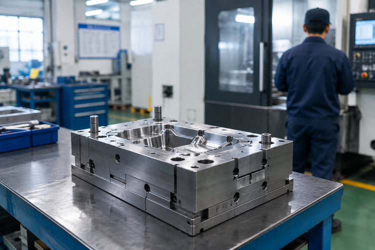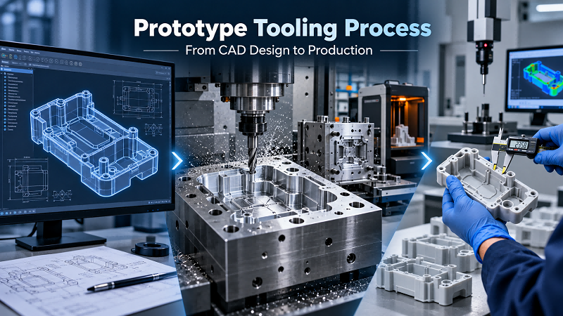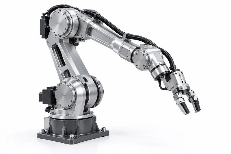
Robot arm CNC machining changes raw aluminum, steel, and engineering plastics into gears, joints, mounts, and housings. These parts often hold tolerances of ±0.001 to ±0.005 inches. That range isn’t guesswork. Published robotics benchmarks list tolerances of ±0.005 in for arm links up to 100 mm, ±0.002 in for bearing bores and gear interfaces, and ±0.002 in for servo mounting planes.
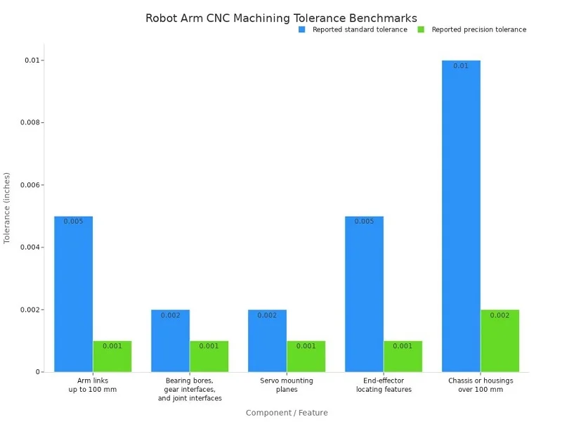
General CNC machining guidance lists ±0.005 in as a common bilateral tolerance. Precision housing work is tighter: shaft bores stay within ±0.001 in, and concentricity is 0.002 in. Materials, tolerances, precision requirements, and manufacturing challenges all affect the final part.
Robot Arm CNC Machining and Common Components
Defining Robot Arm CNC Machining
Subtractive Manufacturing for Robotic Parts
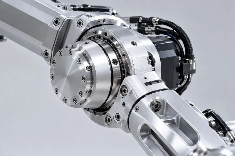
Robot arm CNC machining is a subtractive process. It cuts material away from a solid block until the desired shape appears. Casting and forging shape material with a mold or die, so this method is different. 3D printing builds parts layer by layer, so this method is different too. Subtractive methods work best for CNC machined robot parts when tolerances are tighter than ±0.01 mm. Complex shapes and production runs from 10 to 5,000 pieces also favor this approach.
Prototype and Production Roles
CNC machining covers both prototyping and production. Shops use 3+2 axis and simultaneous 5-axis machining as a dependable bridge between the two. 3D printing is fine for prototypes and lattice structures. But CNC machined robotic parts stay the top choice when strength-to-weight ratio, surface finish, and metal fatigue life matter. Articulated joints, end-effectors, gearboxes, and sensor housings all depend on that reliability.
Core Mechanical Components
Base and Mounting Plates
Bases and mounting plates are the foundation. These parts need to be flat and stable. MIC-6 cast aluminum plate and Durabar are common picks for large flat plates. They keep their flatness after machining because of low internal stress.
Arm Segments and Links
Arm segments carry loads and set how far the robot can reach. Aluminum 7075-T6 and 6061-T6 are the usual materials here. Both are light, strong, and easy to machine. Anodizing makes these surfaces resist wear better.
Wrist and End-Effector Interfaces
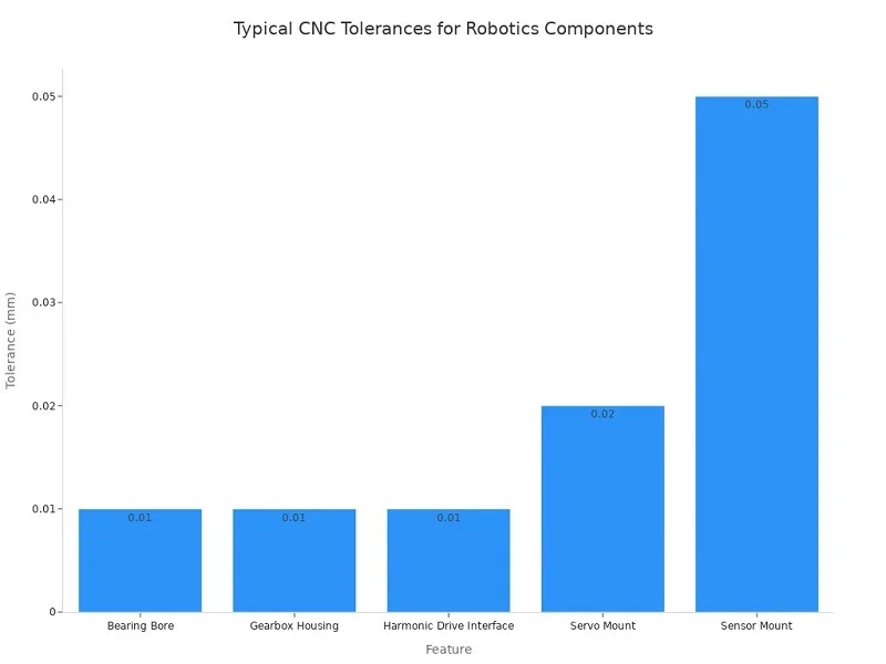
Wrist interfaces connect the arm to the tool. These CNC machined robot parts need tight fits. A servo mount usually holds ±0.02 mm. Sensor mounts stay within ±0.05 mm. Any looseness here shows up as positioning error at the tool tip.
Joint and Drive Components
Harmonic Drive Housings
Harmonic drive housings need extreme precision. Their interface tolerance is ±0.01 mm. Surface roughness is Ra 0.8 to 1.6 μm. These CNC machined robot parts directly affect backlash and repeatability.
Bearing Caps and Retainers
Bearing caps keep shafts aligned. Bearing bores hold ±0.01 mm. Surface finish for bearing seats is Ra 0.4 to 0.8 μm. An H7 tolerance lets a bearing sit firmly without rattling or warping the race.
Motor Mounts and Couplings
Motor mounts and couplings transfer torque. A standard CNC tolerance of ±0.10 mm works for frame links and motor mounts. That level covers about 80% of robot components. For robot arm CNC machining that carry high loads, 17-4PH stainless steel or 4140 alloy steel handles the stress.
In practical terms, robot arm CNC machining ties directly to motion quality. Gears, joints, mounts, and housings must be made with high precision so the robot moves smoothly and positions accurately. Precision CNC machining is essential for exact sizes down to tiny fractions of a millimeter. So the robot parts best suited for CNC machining include joint housings, bearing blocks, robot bases, arms, mounting plates, brackets, and other CNC machined robot parts where bearing fits and bearing seats decide real-world performance.
Robot Arm CNC Machining: Key Processes
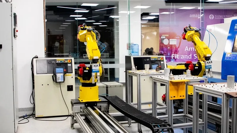
Milling, turning, drilling, and tapping are the main methods used in robot arm CNC machining. Today’s shops use 3-axis, 4-axis, and 5-axis machines. Each machine can handle a different amount of shape complexity. Choosing the right method for each feature helps keep costs low and accuracy high.
5-Axis CNC Milling
Complex Geometries and Undercuts
In 5-axis machining, the tool moves along the X, Y, and Z straight axes while the workpiece tilts or spins on two turning axes. This at-the-same-time motion lets the cutter reach angles that a straight-up spindle could never touch. The tool angle changes all the time to keep the best cutting position. Shaped surfaces come out smoother, with less shaking and tool bending. Undercuts and deep angled surfaces become normal jobs instead of impossible ones.
The gap between this and 3-axis work is huge. A 3-axis machine copies complex shapes using many tiny straight cuts, which leaves marks behind. Undercuts need special tools or extra times turning the part. Angled holes require custom holders for every angle. A 5-axis machine does all of it in one steady pass.
| Feature / Process Step | 3-Axis Machining | 5-Axis (Multi-Axis) Machining |
| Complex contours | Copied with many tiny straight cuts, leaving marks | Steady tool movement makes a smooth, exact surface in one pass |
| Undercuts | Not possible without special tools or many setups and turning the part | Tool tilts to reach under features without moving the part |
| Angled holes | Needs custom holders or turning the part for each angle | Workpiece or tool head is tilted to the exact spec for drilling |
| Number of setups | 3–6+ per part | 1–2 per part |
| Programming time | Higher (many programs) | Lower (one complex program) |
| Machining time | Higher because of setup changes | Much lower |
| Risk of error | High (human error in setups) | Very low (machine controlled) |
Reducing Setup Count
Setup count drives both cost and mistakes. A 3-axis job may need three to six setups per part. A 5-axis job usually needs one or two. Every flip and re-clamp adds stacked-up error. Machining from a single hold position cuts every feature against the same coordinate reference. That matters for tight geometric tolerancing between features on opposite faces.
Shorter, stiffer tooling is another plus. Tilting the spindle or table shows the surface at a better angle, so tools can run shorter with less sticking out. Less sticking out means less bending, better surface finish, and less chatter on thin-walled aluminum sections. Chip removal also gets better, since the best cutting angle helps clear chips from the cutting zone. For heat and built-up edge control in aluminum, that is a real plus.
CNC Turning and Turn-Mill
Cylindrical Joints and Shafts
Turning is great for round features. Round robot arm joints, shafts, and bearing seats all fit this group. Steady cutting gives high material removal rates and tight round tolerances. A stepped 12-inch shaft can come off the machine in about 3 to 8 minutes. Diameter tolerances often reach ±0.0002 to ±0.001 inches. Precision boring fine-tunes bearing seat IDs to press-fit grade. Bearing housings often need ±0.0005 inches, and anti-vibration bars keep deep bores straight.
Live Tooling for Cross Features
Turn-mill centers take the process further. A 4-axis rotary A or B axis indexes or steadily spins the workpiece. Shafts with cross holes and robot arm joints get machined on many faces without moving the part. Live tooling plus a C-axis lets powered tools mill, drill, and tap at set angles. Add a Y-axis, and off-center features and cross-holes become possible. A sub-spindle picks off the backside and finishes the part in one cycle. Fewer setups, shorter lead times, and better accuracy come next.
Drilling, Tapping, and Secondary Operations
Anodizing and Passivation
Finishing protects the part after cutting. Anodizing builds a wear-resistant oxide layer on aluminum robot arm parts that machining projects often call for. Passivation removes free iron from stainless steel surfaces and brings back corrosion resistance. Both steps matter for CNC machined robotics components that face repeated motion and harsh environments.
Precision Grinding and Honing
Grinding and honing tighten what milling and turning cannot. Grinding holds critical diameters and flatness on hardened or heat-treated parts. Honing fine-tunes bore shape and surface finish inside hydraulic and bearing bores. These secondary operations add cost, so engineers save them for working surfaces where fit and wear life decide performance. In a real sense, robot arm CNC machining works best when each feature gets the cheapest process that still meets its tolerance.
Why Precision Matters in Robot Arm CNC Machining
Tolerance Impact on Kinematic Accuracy
Positioning Repeatability
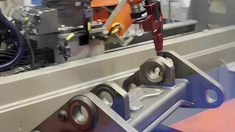
Small errors add up fast, so harmonic drive housings must hold ±0.01 mm. If a bearing seat is off by just 0.01 mm, it adds vibration and friction. Multiply that across six joints, and the end effector will land in the wrong spot every cycle.
“A robot can only be as repeatable as the tolerance stack-up in its joints and drivetrain. Bearing bore concentricity, gear tooth accuracy, and true position of mounting features all control how precisely the end effector lands.”
That quote captures the whole problem: harmonic drive housings are mounting points for bearing seats, spline interfaces, and encoder mounts. When those features shift, backlash grows and positioning accuracy drops.
Backlash and Vibration Control
When bearing bores are held within a few microns, vibration stays low and bearings last longer. Loose bearing fits do the opposite: they raise operating temperature, spread loads unevenly, and shorten service life. High precision robot arm parts machining focuses on these critical surfaces first. The usual failure modes are fatigue, wear, and corrosion, and proper material selection plus surface treatments keep them under control.
Advantages Over Other Methods
Compared to Casting and Forging
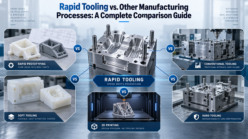
Casting and forging need molds or dies, and making that tooling costs money and time. CNC machining skips that step entirely and holds tight tolerances that cast parts cannot reach without extra work.
Compared to 3D Printing
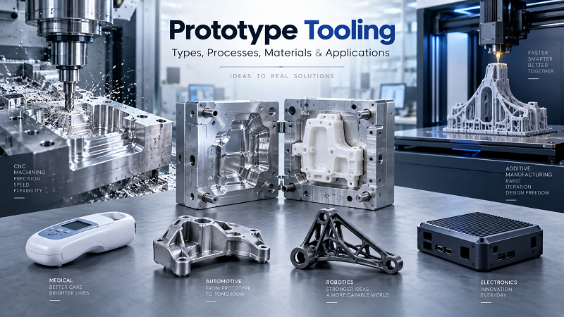
3D printing is better for lattice structures and quick concept models, while CNC machined robotics components are better for fatigue life, surface finish, and strength-to-weight ratio. So working prototypes and end-use parts usually use CNC.
Cost and Lead Time Factors
When Precision CNC Is Justified
Total project cost is about material cost plus machining time, setup and tooling, and post-processing and inspection. The material grade sets the price: aluminum 6061 is far cheaper than titanium or PEEK. Five-axis and turn-mill machines cost more per hour than 3-axis mills. Setup overhead is the biggest cost for small batches of one to five parts.
Balancing Speed and Accuracy
DFM changes can cut cost by 10 to 30%. Standard corner radii, no deep narrow pockets, and fewer tight tolerances all help. Inspection should focus on critical dimensions, not every feature. A partner like NOBLE, a leading manufacturing company in China, helps clients move from prototype to mass production without paying too much for either speed or accuracy.
Materials for Robot Arm CNC Machining
Aluminum Alloys
6061-T6 for Structural Parts
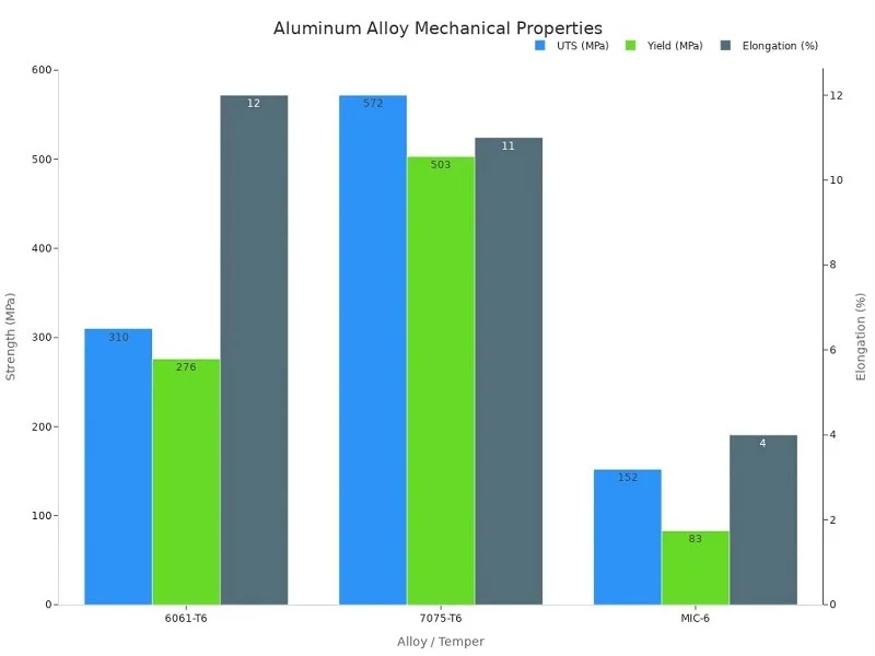
6061-T6 is the go-to choice for most structural parts. It machines easily, welds well, and responds nicely to anodizing. Its tensile strength reaches 310 MPa, and yield strength hits 276 MPa. That mix of good properties and low cost keeps it at the top for robot arm parts machining.
7075-T6 for High Strength
7075-T6 delivers serious strength. Tensile strength is 572 MPa, and yield strength is 503 MPa. That’s about 3.5 times stronger in tension than MIC-6 cast plate. It machines well but wears tools down faster than 6xxx alloys. High-load structural parts get the most benefit from this grade.
MIC-6 Cast Plate for Flatness
MIC-6 is a cast tooling plate made for flatness and dimensional stability. Its flatness tolerance is ±0.005″ on thick plate, compared to ±0.030″ for standard 7075-T6. In a 50-cycle thermal cycling test (68°F–200°F, 12″×12″×0.5″ samples), MIC-6 changed size by only 0.0008 in, while 6061-T6 rolled plate changed 0.0035 in. That’s a 77% stability improvement. MIC-6 has lower mechanical strength, so it works best for fixtures, bases, and precision plates.
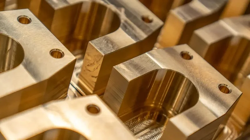
Residual stress distortion — commonly called “potato chipping” — happens when one face of a stressed billet is machined first, releasing locked-in compressive forces and warping the part in unpredictable ways. For thin-walled parts or flatness-critical fixtures, specify stress-relieved stock (T651 temper for 6061), or use a symmetric material removal sequence that balances forces on both faces before taking finishing passes.
Stainless Steel and Durabar
304 and 316L Grades
304 and 316L stainless steels give you corrosion resistance and durability. These grades appear in medical instruments, food processing equipment, and marine components. 316L adds molybdenum for better resistance to chlorides and harsh chemicals.
17-4 PH for High Strength
17-4 PH is a high-strength option for robotics components that need corrosion resistance and fatigue performance. In the H900 condition, its yield strength is above 1170 MPa. Output shafts, high-load pins, and joint yokes for food processing or medical sterilization robots all use this grade.
Durabar for Large Flat Plates
Durabar is often specified for large flat structural plates. It holds guaranteed flatness and low internal stress after machining. That makes it a solid pick for robot bases and mounting plates where stability matters.
Titanium and Engineering Plastics
Ti-6Al-4V for Weight-Critical Joints
Ti-6Al-4V (Grade 5 titanium) offers the highest strength-to-weight ratio of any metallic element. It resists corrosion exceptionally well and is biocompatible. High-stress robot arm joints, aerospace brackets, and semiconductor end-effectors rely on it where weight reduction is critical.
PEEK and Delrin for Insulation and Wear
PEEK handles chemical resistance, high-temperature performance, and electrical insulation. Semiconductor and aerospace robots use it where outgassing must be minimized. Delrin (POM) brings low friction, wear resistance, and high stiffness. Custom gears, bushings, and sliding mechanisms within robotic joints benefit from its dimensional stability. These CNC machined robotics components reduce wear in moving interfaces. From a practical perspective, robot arm CNC machining often pairs metals with these plastics to solve insulation and wear problems at once.
Tolerances and Precision Requirements in Robot Arm CNC Machining
Typical Tolerance Ranges
General Machining Tolerances
Robot arm CNC machining usually keeps general sizes between ±0.001 and ±0.005 inches. ISO 2768-m covers most features that are not critical. It allows about ±0.1 mm for parts under 30 mm. This works for structural robot arm parts where exact fits are not needed.
Tight tolerance CNC machining goes on working faces. Cosmetic shells and ribs can use looser classes. Sort these areas out early to keep costs down. ISO 2768 classes go from f (tightest) to v (very coarse). Class m is the normal benchmark for CNC work.
Critical Fit Tolerances
Critical features need tight tolerances. Bearing bores and gearbox housings stay within ±0.01 mm. Harmonic drive interfaces match that, with Ra 0.8 to 1.6 μm. Servo mounting surfaces hold ±0.02 mm. Sensor mounts hold ±0.05 mm. These are common CNC tolerances for robotics components.
Bearing fits control shaft alignment. Standard bearing fits use H7/p6 press fits for fixed races. They use H7/g6 clearance fits for rotating joints. These bearing fits stop races from spinning. Tight tolerance control prevents vibration and wear.
A ±0.05 mm per-part tolerance builds up across a joint. Three components create ±0.15 mm total stack-up. Check bearing seats as one assembly, not as single parts.
Surface Finish Specifications
Ra Values for Bearing Seats
Surface roughness controls friction and wear. Bearing seats on machined housings usually need Ra 0.4 to 0.8 μm. Superfinished bearing steel reaches Ra 0.05–0.1 μm, but housings almost never need that. For CNC machined robotics components, Ra 0.8 μm works for bearing bores.
Working surfaces like polished PEEK tendon guides reach Ra 0.2 μm. Bearing seats, seal lands, and precision sliding guides all gain from controlled roughness. Put this on the drawing.
Cosmetic vs. Functional Finishes
Cosmetic surfaces can stay at Ra 0.8–1.2 μm after micro-blasting and Type II anodize. Faces that do not touch anything sit at Ra 3.2 μm. One housing can have both smooth working zones and rough cosmetic zones.
Mirror-grade finishes add fatigue strength by removing points where stress builds up. Smooth faces also cut friction on bearing contact areas. So finishing choices connect with precision requirements and tolerances across the whole part.
Inspection and Quality Control
CMM and Optical Inspection
Coordinate Measuring Machines (CMMs) check complex 3D shapes and CTQ dimensions. Height gauges and micrometers handle straight sizes. Vision systems measure small 2D features. Laser scanners capture delicate surfaces without touching them.
Geometric dimensioning and tolerancing (GD&T) sets these checks. When a drawing uses true position, the CMM becomes a must. For robot arm CNC machining, inspection ties design intent to the real part.
First Article and In-Process Checks
First Article Inspection (FAI) checks the first part against the CAD model before batch production. Aerospace suppliers formalize this under AS9102. In-process inspection uses SPC to catch tool wear drift. High-precision series production aims for Cpk ≥ 1.67.
Final inspection picks a plan: 100% measurement, random sampling, functional testing, or visual checks. Sharp manufacturers use these steps to prove CNC machined robotics components meet tolerance, gd&t, and surface finish requirements.
Design and Manufacturing Challenges for Robot Arm CNC Machining
Design for Manufacturability
Avoiding Sharp Corners
Sharp inside corners are a common problem in robot arm CNC machining. Standard end mills are round, so they always leave a curve behind. If you ask for a perfectly sharp 90-degree corner, you need EDM or another slow, costly step. A better way for design for robot arm CNC machining is to add a small rounded edge in every inside corner. A minimum vertical corner radius of 0.2 mm to 0.5 mm works for most materials. This lets the cutter cut smoothly and lowers stress buildup.
Minimizing Deep Pockets
Deep, narrow pockets slow the spindle and wear out tools quickly. The suggested cavity depth should not be more than four times the cavity width. If a pocket is 10 mm wide, its depth should stay under 40 mm. This ratio helps chips flow out, reduces tool bending, and keeps surface finish steady. A good rule for design for robot arm CNC machining is to make the corner radius at least one-eighth of the cavity depth. That lets a shorter, stiffer tool run at higher feed rates.
Using Standard Tool Sizes
Non-standard holes and thread sizes raise costs without adding value. Standardize hole diameters and thread pitches whenever you can. Also, keep wall thickness above 0.8 mm for metals and 1.5 mm for plastics. Avoid features smaller than 2 mm unless you really need them. These design for robot arm CNC machining habits cut down tool changes, shorten cycle times, and lower the risk of broken tools.
Flatness and Residual Stress
Maintaining Flatness on Large Parts
Large plates and bases are hard to keep flat. Residual stress is locked-in internal stress that shifts once material is removed or clamps are released. A face that looks flat while clamped may relax after unclamping. For a large machine base, one shop reached flatness of 7 µm over 2000 mm, beating their goal of under 10 µm. They used balanced roughing, intermediate stress relief, and controlled finishing passes.
Minimizing Distortion
Uneven material removal makes plates and thin-wall parts bow or twist. Symmetrical machining and staged cutting lower stress imbalance. Cutting heat also causes temporary thermal expansion and post-cooling shrinkage. Sharp tools, stable coolant, and controlled finishing passes help. For stress-sensitive alloys, intermediate thermal relaxation between roughing and finishing can hold tolerances within +/-0.005 mm. A rough-rest-finish sequence lets the part release stress before final passes.
Tolerance and Cost Balance
Achieving Tight Tolerances
Tight tolerances belong on critical interfaces only. Bearing bores, motor pilot diameters, and gear interfaces carry most alignment responsibility. These features may need limits near ±0.005 mm. But using that level everywhere increases machine time, tooling wear, and inspection load. Tolerance stack-up matters too. Combined errors across a chain of CNC machined robotics components can cause misalignment even when each part passes inspection.
Reducing Machining Costs
Function-driven tolerance allocation keeps costs down. Weight-reduction pockets, covers, and clearance holes can use commercial tolerances around ±0.05 mm. Early DFM review spots deep pocketing issues and relaxes non-critical tolerances. One estimate puts spindle run-time savings at up to 40% from these changes. From a practical perspective, robot arm CNC machining works best when precision follows function, not convention. That balance keeps tolerance, gd&t, and surface finish requirements realistic for both prototypes and production runs.
Robot Arm CNC Machining Applications Across Industries
Industrial Automation
Pick-and-Place and Welding Arms
Pick-and-place arms are built for speed. They race through thousands of cycles every hour, so every bit of moving weight counts. Light aluminum robotic parts help keep that weight low. Common parts include robotic arm housings, joint assemblies, servo motor mounting brackets, rotary shafts, and end effector connectors. Aluminum 6061, 7075, and 6082 are the usual choices here.
Welding arms deal with a much tougher life. Spatter, heat, and nonstop movement wear down every joint. Gearbox housings and precision bearing seats must keep their fit through all of it. Most robotic arm parts need tolerances between ±0.01mm and ±0.02mm, depending on the job. That range keeps the torch path steady shift after shift.
Collaborative Robot Joints
Cobots work side by side with people. Safety depends on smooth, predictable motion. A joint that sticks or shakes is a danger, not just a quality issue. This is where robot arm parts machining proves its value. Joint housings must fit bearings, sensors, and cable routing into a small space while staying stiff.
Multi-axis CNC milling handles that in one setup. Lightening pockets, internal passages, and shaped joint housings all come off one machine. Fewer times repositioning the part means less stacked-up error. Stainless steel often goes into the joint reducer housing for wear and corrosion resistance. PEEK bushings handle electrical insulation inside the same assembly.
Medical and Surgical Robotics
Sterile-Compatible Components
Surgical robots need cleanliness and repeatability in equal amounts. Parts must survive repeated sterilization without pitting or warping. Stainless steel 316L and titanium Ti-6Al-4V are common choices. Both resist corrosion and handle harsh cleaning cycles. Titanium adds biocompatibility, which matters for anything near the patient.
Medical device production often holds tolerances of ±0.0002 inches. That’s much tighter than general machining work. Sensor housings, motor mounts, and drive train parts all fall under that umbrella. Surface finish matters too. Smooth bearing seats cut friction and shed contaminants instead of trapping them.
High-Precision Surgical Links
Surgical links turn motor input into millimeter-scale tool motion. Any backlash shows up as tremor at the tip. Articulated joint mechanisms for precise operations are machined to ±0.0002-inch tolerances for exactly this reason. Rotary shafts and bearing seats carry most of that burden.
One practical note: robot arm CNC machining for these links often pairs turning with milling. Shafts come off the lathe, then cross features get cut on a turn-mill center. Keeping both operations in one family reduces handling and protects the tight fits.
Aerospace and Defense
Lightweight Structural Parts
Weight is the enemy in aerospace. Every kilogram saved pays back in payload and fuel. Aluminum 7075 works well for upper arm structures thanks to its high strength-to-weight ratio. Structural frames, chassis, and manipulators follow the same logic. Milling creates the prismatic shapes, pockets, and complex contours these parts need.
Defense robots add another layer. They operate in dust, salt, and temperature swings. Corrosion-resistant alloys and sealed enclosures keep them running. Manufacturing of components requiring high precision routinely hits ±0.0002-inch tolerances in this sector.
High-Strength Joint Assemblies
Joint assemblies carry the full load path of the arm. They need strength, stiffness, and fatigue life all at once. Stainless steel 17-4PH and titanium handle high-stress joints where aluminum would fatigue too soon. Gearbox covers, mounting brackets, and end effector interfaces round out the typical part list.
Aerospace fabrication also leans on multi-axis capability. Contoured joint housings with internal passages get machined in one sequence, which keeps concentricity between bearing bores intact. That single-setup approach is what makes compact, integrated joint designs possible.
NOBLE: Your Robot Arm CNC Machining Partner
Metal and Plastic Machining Expertise
Aluminum, Stainless Steel, Titanium, and Engineering Plastics
NOBLE machines all the common robot arm materials. Aluminum works for light arms and platforms because it lowers inertia and fights rust. Stainless steel fits shafts, pins, and clean spaces that are easy to wash. Titanium gives aerospace and medical joints an amazing strength-to-weight ratio. Engineering plastics like PEEK and Delrin take care of insulated parts, wear-resistant guides, and sensor housings.
That range matters because one robot mixes materials. A joint housing might be aluminum, its shaft 17-4 stainless, and its bushing PEEK. NOBLE keeps all of them under one roof, so fits stay consistent across the assembly.
Prototype to Production Volumes
The provider grows its processes to handle fast prototyping, one-off machined parts, small-batch production, and large-scale manufacturing runs. It keeps quality steady and delivers on time at every stage.
A single bracket and a 5,000-piece run get the same process control. Documented fixturing, proven tool paths, and steady setups keep parts the same size across batches. Batch repeatability matters for modular robot assemblies, where every unit must work the same way.
Certifications and Quality Systems
ISO 9001:2015 and ISO 13485:2016
NOBLE holds ISO 9001:2015 and ISO 13485:2016 certifications. The first covers general quality management. The second adds the medical device rules that surgical robotics demands. Both require material control, revision management, nonconformance handling, and lot traceability.
Inspection and Documentation
Every robotic component passes multi-stage inspection, including CMM validation against GD&T. Micrometers, bore gauges, height gauges, thread gauges, roughness testers, and optical systems fill in where a CMM is too much. First article inspection confirms the process before a batch moves on. In-process checks catch tool wear, fixture movement, or thermal drift.
| Document | What it proves |
| Material/mill test reports | Correct alloy and heat lot |
| FAI and CMM reports | Dimensions match the drawing |
| Certificates of conformance | Spec compliance |
| Lot traceability records | Which batch shipped where |
Each document lists the part number, revision, material lot, and production batch.
Full-Service Manufacturing
Design, Machining, Finishing, and Assembly
NOBLE treats robot arm CNC machining as one stage of a project, not the whole job. DFM reviews flag deep pockets and sharp corners before chips fly. After cutting, anodizing, plating, and passivation stay under the same quality system, so size changes stay documented. Assembly covers threaded inserts, bearing pressing, and pin mounting.
Single-Source Project Management
One team manages programming, tooling, workholding, inspection, outside processing, documentation, and assembly. That cuts the coordination load across suppliers. English documentation, inspection reports, and stable packaging round out the package. From a practical perspective, that single-source model is what keeps prototype and production orders moving on schedule.
Robot arm CNC machining comes down to three choices you make early: part shape, material grade, and how tight the tolerances need to be. Working faces like bearing seats and gear interfaces need ±0.001 to ±0.005 inches and a finish of Ra 0.4 to 1.6 micrometers. Cosmetic surfaces can use looser limits. Material matters too, since MIC-6 and Durabar keep large bases flat. Fatigue, wear, and corrosion are the usual ways parts fail, and the right alloys plus surface treatments fight them off. Follow DFM rules: skip sharp inside corners and keep deep pockets to a minimum. In a practical sense, robot arm CNC machining costs go down without losing precision. Work with a certified manufacturer like NOBLE for material traceability, documented inspection, and help from prototype to production. The right choices give you a robot that is precise, durable, and repeatable.
FAQs of Robot Arm CNC Machining
What tolerances can robot arm CNC machining really hold?
Most general sizes fall between ±0.001 and ±0.005 inches. Important fits need to be even tighter. Bearing bores and harmonic drive interfaces stay within ±0.01 mm, servo mounts within ±0.02 mm, and sensor mounts within ±0.05 mm. Surgical links can reach ±0.0002 inches. So the answer really depends on which feature you are asking about.
Which aluminum grade should I choose for a robot arm?
It depends on the job. 6061-T6 works for most structural parts and has 310 MPa tensile strength. 7075-T6 gives you 572 MPa for links that carry heavy loads. MIC-6 cast plate is best when flatness matters most, because it holds ±0.005″ flatness and hardly moves during thermal cycling.
When does CNC beat 3D printing for robotic parts?
3D printing is fine for concept models and lattice structures. Robot arm CNC machining wins when you need parts that last, a real surface finish, or a strength-to-weight ratio that holds up in use. Working prototypes and end-use parts usually go the CNC route.
Why do large base plates warp after machining?
Residual stress is the reason. When you machine one face, locked-in forces are released, and the part bows — shops call this “potato chipping.” MIC-6 and Durabar resist this because they have low internal stress. A rough-rest-finish sequence also lets stress escape before the final passes.
What surface finish do bearing seats need?
Bearing seats on machined housings usually need Ra 0.4 to 0.8 μm. Harmonic drive interfaces sit at Ra 0.8 to 1.6 μm. Cosmetic surfaces can stay rougher, around Ra 3.2 μm. Put the number on the drawing so the shop knows which faces matter.
What drives the cost of robot arm CNC machining?
Four things: material grade, machining time, setup and tooling, and inspection. Aluminum 6061 costs far less than titanium or PEEK. Five-axis and turn-mill machines have higher hourly rates. For batches of one to five parts, setup overhead is the biggest cost of all.
How do I keep precision without blowing my budget?
Put tight tolerances only on working faces. Bearing bores, motor pilots, and gear interfaces carry the alignment load. Pockets, covers, and clearance holes can use commercial tolerances near ±0.05 mm. Early DFM review can cut spindle run-time by up to 40%.
What should I look for in a robot arm CNC machining supplier?
Look for material traceability, documented inspection, and certifications that match your industry. ISO 9001:2015 covers general quality management. ISO 13485:2016 adds the medical device rules that surgical robotics demands. CMM reports and first article inspection should come as standard.