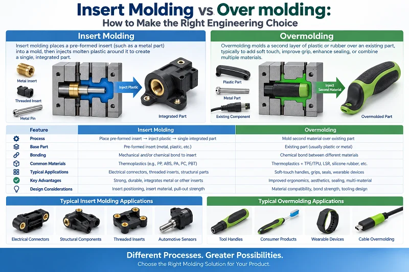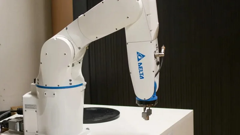
The most common ways to make robotic arm components are CNC machining, DMLS, injection molding, die casting, investment casting, and forging. For robotics materials, you’ll mostly see metals like stainless steel and titanium, plastics, and composites. Picking the right mix of robotic arm components comes down to strength, weight, cost, and durability. A robotic arm for heavy automation needs different robotic arm components than one for precision assembly. This guide covers materials, manufacturing methods, selection factors, and real-world challenges. You’ll learn how each choice shapes robotic automation systems, from the robot base to the end effector. Every decision about robotic arm components matters for performance.
Materials for Robotic Arm Components
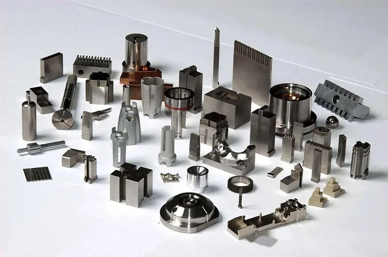
Common Robotics Materials: Plastics, Metals, Composites
Common robotics materials come in three groups: plastics, metals, and composites. Each group has many different grades. The grade you choose affects strength, weight, and cost. Robotic arm components include joints, actuators, sensors, end effectors, and structural housings. Each of these robotic arm components needs its own kind of material.
Engineering Plastics
Engineering plastics are used for covers, sensor housings, and light-duty end effectors. They are strong and easy to mold, and they cost less than most other engineering materials.
Metals: Stainless Steel and Titanium
Metals carry the heavy loads in robotics. Stainless steel gives high strength and good rust resistance. Titanium is lighter and stronger for its weight. It also resists rust. These two metal types appear in actuators, drive shafts, and joint housings. Other alloys matter too. The table below shows how a few common metals in robotics compare.
| Material Designation | Density (g/cm³) | Yield Strength (MPa) | Primary Robotic Application |
| Al7075-T6 Aluminum | 2.81 | 503 | High-stress structural brackets, link mounts |
| AZ91D Magnesium | 1.81 | 150 | Lightweight robot arm links, casing panels |
| AISI 4140 Steel | 7.85 | 655 | Heavy-duty drive shafts, planetary gears |
For high-precision actuators, two more alloys often come up. AlSi10Mg prints well and offers balanced properties. A6061 delivers very high strength-to-weight and machines easily.
| Alloy | Key Strengths | Typical Preference in Robotics |
| AlSi10Mg | Excellent printability, good overall properties, high thermal conductivity, corrosion resistance, good fatigue strength | Preferred when printability and balanced properties are critical |
| A6061 | Very high strength-to-weight (enhanceable by heat treatment), good machinability, excellent corrosion resistance, good fatigue strength | Chosen when maximum strength is the decisive factor |
Composites: Carbon Fiber Reinforced Polymers
Carbon fiber reinforced polymer (CFRP) packs high stiffness into a light package. It acts differently from metals. Its properties depend on fiber direction. That trait is called anisotropy. Here is how CFRP compares to aluminum 6061.
| Property | Carbon Fiber Composite (CFRP) | Aluminum 6061 |
| Density | ~1.5–1.7 g/cm³ | ~2.70 g/cm³ |
| Elastic modulus | Direction-dependent | ~69 GPa |
| Tensile strength | Direction-dependent | ~300 MPa (representative) |
| Thermal expansion | Direction-dependent, often low along fiber | ~23 ppm/K |
| Material behavior | Anisotropic | Approximately isotropic |
| Corrosion behavior | Generally excellent for CFRP itself | Good but surface protection may be required |
Research published in IEEE Access has specifically investigated hybrid robotic-arm structures using carbon fiber reinforced plastic and aluminum alloy. The researchers reported a validated prototype with a 24.32% mass reduction compared with the aluminum-alloy reference design.
Properties and Applications
Strength, Weight, and Corrosion Resistance
Strength-to-weight drives most material choices. A lighter arm moves faster and needs less power. Corrosion resistance matters in wet or chemical settings. Stainless steel and titanium hold up well. Aluminum needs surface protection in some environments. CFRP resists corrosion on its own.
Where Each Material Fits in a Robotic Arm Components
Metals go where loads are high. Think gearboxes, drive shafts, and joint housings. Plastics fit covers, cable guides, and light brackets. Composites shine in long arm links and structural tubes. A hybrid design often wins. One study found carbon fiber composites are 42% lighter than aluminum and three times lighter than steel. That makes them the best choice for both materials in weight-critical builds. Reported benefits include:
- 42% lighter than aluminum
- Stiffness increased by 30%
- Greater carrying capacity of the robotic arm components
- Higher operating speed of the robotic arm components
- Increased durability/longer life
Limitations of Each Material Category
Cost, Machinability, and Environmental Factors
Titanium costs more than steel and machines slowly. CFRP needs special tooling and careful layup. Plastics are cheap and fast to mold. They soften at lower temperatures. Metals in robotics handle heat far better. Recycling also differs. Metals recycle cleanly. Many composites do not.
When to Avoid Plastics or Composites
Skip plastics for high-load joints or hot environments. They creep under steady stress. Avoid composites when you need isotropic behavior or low-cost mass production. They also struggle with abrasive wear. For a robot in sanding or metal fabrication, metal robotic arm components usually last longer. For a medical or cleanroom robot, smooth plastic housings can be the better call.
Manufacturing Processes for Robotic Arm Components

CNC machining and DMLS are the main methods for metal parts. For plastics, injection molding is common. Transmission elements like gearboxes almost always come from CNC machining. The process you choose determines the final cost, strength, and precision. Each method fits a specific set of needs in modern robotics. DMLS works well for complex geometries with internal features that CNC cannot reach. Injection molding is the go-to for high-volume plastic robotic arm components.
Forging for High-Strength Components
Forging is a manufacturing process that can be used for high-strength components. It involves shaping metal using compressive forces. This process can be beneficial for robotic arm components that require high strength and fatigue resistance.
Die Casting and Investment Casting
Die casting and investment casting produce complex shapes with good repeatability. These processes are common for housings, brackets, and end effector components in robotics. They work well for many engineering materials. Die casting pushes molten metal into a steel mold under high pressure. Investment casting uses a wax pattern that burns away. Both methods can create features that are hard to machine.
Aluminum and Zinc Die Casting
Aluminum die casting gives strong, light parts. It handles complex geometries and thin walls down to about 1 mm. Zinc die casting is cheaper and easier to cast with high detail. But zinc is heavier and less stiff. For robot housings and structural brackets, aluminum is the better choice. Zinc works well for smaller robotic arm components like sensor brackets and cable guides.
Investment Casting for Complex Geometries
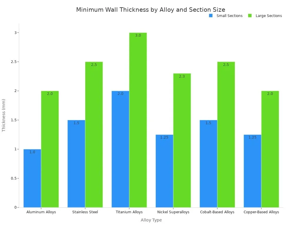
Investment casting uses a wax pattern coated in ceramic slurry. The wax melts out, leaving a cavity. Molten metal fills that cavity. This method creates very detailed shapes with smooth surfaces. The table shows minimum wall thicknesses for different alloys in this materials category.
| Alloy Type | Minimum Wall Thickness (Small Sections) | Minimum Wall Thickness (Large Sections) |
| Aluminum Alloys | 1.0 mm | 2.0 mm |
| Stainless Steel | 1.5 mm | 2.5 mm |
| Titanium Alloys | 2.0 mm | 3.0 mm |
| Nickel Superalloys | 1.25 mm | 2.3 mm |
| Cobalt-Based Alloys | 1.5 mm | 2.5 mm |
| Copper-Based Alloys | 1.25 mm | 2.0 mm |
There is no single minimum wall thickness for every project. Some suppliers claim 2 mm to 3 mm as a baseline. The actual limit depends on part size, geometry, and alloy fluidity. You need to check the specific 3D model to know the safe minimum. For complex robotic arm components, investment casting reduces post-machining work compared to other manufacturing methods. The process is ideal for precision components in automation and robotics systems. It can produce robotic arm components with undercuts and internal passages that other processes cannot.
Surface Finish and Tolerance Considerations
The surface finish on a robotic arm components joint affects movement and lifespan. A proper finish means the bearing outer race makes full contact with the seat. The table below shows the typical roughness values for different features in robotic arm components. Each value serves a purpose. A bearing seat needs a very smooth finish to avoid stress points. A cosmetic housing surface can be rougher because it does not carry load.
| Feature | Typical Surface Roughness (Ra) |
| Bearing Seat | 0.4–0.8 μm |
| Harmonic Drive Interface | 0.8–1.6 μm |
| Servo Mounting Surface | 1.6 μm |
| Cosmetic Housing Surface | 1.6–3.2 μm |
| Internal Non-Critical Features | 3.2 μm |
A surface finish of Ra 0.4 μm on a bearing journal helps a MoS₂ coating bond well. That finish supports consistent film application and good adhesion. When the finish is too rough, the contact area drops. High-stress points appear and can cause micro-fretting over millions of cycles. That hurts performance. The difference between 0.4 μm and 3.2 μm is the difference between a joint that runs smooth for years and one that wears out early.
Achieving Repeatable Joint Alignment
Joint alignment depends on tight tolerances and the right finish. The bearing seat needs Ra 0.4–0.8 μm for correct outer race placement. Machinists use fine feeds and slow speeds to hit these values. A rougher surface makes the bearing shift under load. That misalignment leads to wear and lower accuracy. For a robot that repeats the same path thousands of times, this matters a lot. Even a small misalignment adds up over many cycles.
Metrology and Quality Control
Quality control in manufacturing robot arm robotic arm components uses coordinate measuring machines and surface profilers. CMMs check hole positions and surface flatness. Profilers measure the actual Ra value. These tools verify every dimension stays within spec. The inspection process catches errors before assembly. A part with the wrong finish or out-of-tolerance hole gets rejected. That saves time and keeps the final product reliable. For medical robots or cleanroom automation systems, this level of quality is critical.
Design Considerations for Robotic Arm Components
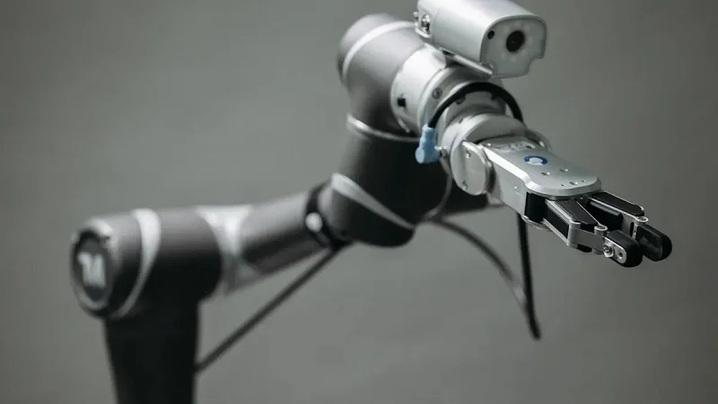
Good design starts with the job the arm must do. Actuators drive every joint. Electric motors suit clean, precise work. Pneumatic cylinders move fast and cheap. Hydraulic units carry huge loads. Each type changes the material choice for nearby robotic arm components. A hydraulic actuator needs seals and housings that resist fluid and pressure. An electric one needs heat paths and light frames. End effectors differ too. A gripper, a sprayer, and a drill all touch the world in different ways. Grippers need tough, light jaws. Sprayers need chemical-resistant bodies. Drills need hard, wear-proof mounts. These needs shape every decision about robotic arm components.
Strength-to-Weight Ratio
Why Payload Capacity Depends on It
Payload capacity falls as arm mass rises. Every kilogram in the arm is a kilogram the motor must move. A heavy forearm steals capacity from the wrist. That is why robotics engineers chase stiffness without weight. Lighter links mean faster motion and lower power draw. For industrial arms running all day, this saves real money.
Material and Geometry Choices
Metals like aluminum and titanium give high strength per kilogram. Composites go further. One IEEE Access study cut arm mass by 24.32% using a carbon fiber and aluminum hybrid. Geometry matters just as much. Ribs, hollow sections, and tapered links remove dead weight. A well-shaped part often beats a fancy material.
Cost Drivers
Raw Material Costs
Titanium costs far more than steel. Carbon fiber prepreg is pricier still. Plastics stay cheap. Raw stock sets the floor for any quote. Buyers should match material to load, not to habit.
Tooling, Labor, and Volume Effects
Forging dies and injection molds incur significant upfront costs. That expense only pays off at volume. Low runs favor CNC machining, which skips tooling. Labor adds up fast on hand-finished robotic arm components. High-volume manufacturing spreads tooling across many units and drops unit price.
Durability and Wear
Fatigue Resistance and Surface Treatments
Cycling loads cause fatigue cracks over time. Surface treatments help metals resist it. Aluminum is soft on its own. Type III hard anodizing fixes that. It grows a ceramic-like oxide layer 40–60 µm thick, integral to the part. Surface hardness tops 60 HRC. That beats untreated aluminum by a wide margin.
| Surface Condition | Surface Hardness | Wear Resistance |
| Untreated aluminum | Soft bulk surface | Scuffs under sliding and grit |
| Type III hard anodized | 60+ HRC | Superior scratch and abrasion resistance |
PTFE impregnation lowers friction further, which enables dry-running bushings.
Environmental Factors and Corrosion
Moisture, chemicals, and grit all attack robotic arm components. Stainless steel and titanium resist corrosion well. Aluminum needs coating in wet settings. Composites resist rust but wear under abrasion. Real-world applications prove this. Sanding, woodworking, and metal fabrication punish sliding surfaces. Pallet stacking and surface treatment reward light, stiff links. Medical and cleanroom robotics demand smooth, cleanable housings. Match the material to the environment, and durability follows.
Selecting Materials and Processes for Robotic Arm Components
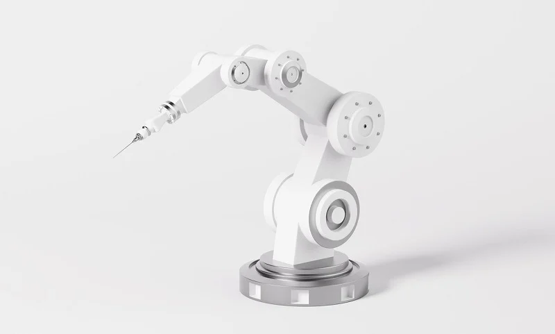
Choosing the right mix for robotic arm components means matching what you need with what each option can do. A material selection guide can help you here. You compare strength, weight, cost, and durability against the job the arm must perform.
Matching Material to Application
High-Speed vs. High-Payload Robots
High-speed robots need links that are light. Carbon fiber composites and aluminum work best for this. They lower inertia and let motors move faster. High-payload robots need stiffness and strength instead. Steel and titanium carry heavy loads without bending. Your choice affects cycle times and how much energy the robot uses.
Cleanroom and Food-Safe Requirements
Cleanroom robotics calls for smooth, non-porous surfaces. Stainless steel stops bacteria from growing. Food processing adds one more layer of rules. Stainless steel stands up to food acids and cleaning chemicals without rusting. Food-compliant polymers work well for end effectors that touch products directly. NSF H1 certified lubricants are required anywhere incidental contact might happen. These materials keep medical devices and food systems safe.
Matching Process to Production Volume
Prototyping vs. Low-Volume Production
For prototypes, CNC machining and DMLS give you speed without tooling costs. DMLS can make complex internal channels that cutting tools cannot reach. CNC holds tight tolerances for critical interfaces. A hybrid approach works well here. Print the near-net shape, then machine bearing seats and threads to ±0.005 mm. This blends design freedom with precision.
Mass Production Economics
High volumes favor injection molding for plastics and die casting for metals. Tooling costs get spread across thousands of units. Unit prices drop quickly. For 10 to 2,000 units, CNC machining often wins on cost and throughput. Past that point, dedicated tooling pays off.
Testing and Validation
Mechanical Testing Methods
Testing shows whether a design works. Tensile tests check strength. Fatigue tests copy millions of cycles. Hardness tests confirm surface treatments. These methods find weak points before production starts.
Real-World Cycle Testing
Lab tests cannot copy every condition. Real-world applications expose robotic arm components to grit, moisture, and vibration. Sanding and woodworking punish sliding surfaces. Pallet stacking rewards stiff, light links. Run the arm through its actual motions. Measure wear and alignment over time. This proves the design works for automation systems that run all day.
| Application / Requirement | Recommended Method | Material Choice | Achievable Tolerance |
| Precision Fluid Block | 5-Axis CNC Milling | Al6061-T6 | ±0.010 mm |
| Complex Internal Channels | DMLS | Tool Steel 1.2709 | ±0.008 mm |
| Visual Mockup | SLA 3D Printing | UV-Curable Resin | ±0.15 mm |
NOBLE’s Robotic Arm Components Expertise

Manufacturing partners should be able to handle a range of processes including CNC machining, DMLS, injection molding, and casting for robotic arm components. They should also have quality control measures in place.
Plastics, metals, and composites each have a job in robotics. Metals carry heavy loads. Plastics keep robotic arm components light and cheap. Composites give high stiffness for links where weight matters most. The best choice depends on strength, weight, cost, and durability. Manufacturing processes matter too. CNC machining gives tight tolerances for joints. DMLS makes complex internal channels. Die casting and investment casting handle complex housings. Forging can be used for high-strength components. A skilled manufacturing partner helps you choose the right mix. They work with both metal and plastic. That lowers risk and boosts quality. In the future, hybrid processes and new materials will keep expanding what a robotic arm can do. Better combinations mean lighter arms, faster cycles, and new uses in areas like medical automation.
FAQ of Robotic Arm Components
What materials work best for robotic arm components?
It depends on the job. Metals like steel and titanium carry heavy loads. Plastics suit covers and sensor housings. Carbon fiber reinforced polymers fit long links where weight matters most. Match the material to strength, weight, cost, and durability needs.
Which manufacturing process should I pick?
CNC machining and DMLS handle metal parts with tight tolerances. Injection molding works for plastic parts. Casting shapes complex housings. Forging can be used for high-strength robotic arm components. Your production volume and part geometry decide the winner.
When is CNC machining better than 3D printing?
CNC wins for tight tolerances and smooth surfaces. It holds bearing seats at Ra 0.4–0.8 μm. DMLS shines for complex internal channels that cutting tools cannot reach. A hybrid approach works well: print the near-net shape, then machine critical interfaces to ±0.005 mm.
How do I choose between plastics and metals?
Pick plastics for light loads, covers, and cleanroom housings. They cost less and mold fast. Skip them for hot spots or high-load joints, since they creep under steady stress. Metals handle heat, wear, and heavy cycles far better. Composites fit weight-critical links.
What drives the cost of robotic arm components?
Raw stock sets the floor. Titanium and carbon fiber cost more than steel or plastics. Tooling adds significant upfront costs for forging dies and injection molds. That expense pays off at high volume. Low runs favor CNC machining, which skips tooling entirely.
Why does surface finish matter so much?
A smooth finish lets bearings seat correctly. Rough surfaces cut contact area and create stress points. Those points cause micro-fretting over millions of cycles. The gap between Ra 0.4 μm and Ra 3.2 μm decides whether a joint runs smooth for years or wears out early.
How do I test robotic arm components before mass production?
Run mechanical tests first, then simulate real use. Sanding and woodworking punish sliding surfaces. Pallet stacking rewards stiff, light links. Measure wear and alignment over time. This proves the design works for automation systems that run all day.
What should I look for in a manufacturing partner?
Look for a partner with experience in both metal and plastic processing. Check for relevant quality certifications. Ask about design, assembly, and testing support. A partner who covers the full path from design to fulfillment lowers your risk. That matters in robotics, where every part affects the whole arm.