Selecting a manufacturing process for IVD fluidic components is a big challenge. This choice affects performance, cost, and regulatory compliance. No single answer works for every project. You must think about material properties, dimensional precision, production volume, budget constraints, and time-to-market. Each factor carries a lot of weight.
The risks are high. Choosing the wrong process can cause expensive redesigns, delayed approvals, and hurt assay reliability. IVD tests need steady and repeatable fluid handling. Small changes can make results wrong.
This guide looks at the key selection criteria, compares common manufacturing methods, and gives a simple decision framework. IVD systems need precise engineering. By the end, you will have a clear way to make a smart choice for your specific diagnostics application.
Key Selection Criteria for IVD Fluidic Components
Choosing the right manufacturing process for IVD fluidic parts starts with knowing the core needs. Three main factors drive the decision: material compatibility, dimensional precision, and design for manufacturability. Each one directly affects which process you pick and how well the final device performs.
Material Compatibility and Performance
Chemical Resistance and Biocompatibility
Materials in diagnostic devices must handle the harsh chemicals used in molecular diagnostics. Biological samples, cleaning agents, and sterilization methods can damage poorly chosen materials. If chemicals leak out or break down, test results become unreliable and patient safety is at risk.
ISO 10993 sets the rules for biocompatibility in medical devices. If you swap materials, you must run biocompatibility tests again. This includes chemical checks per ISO 10993-18, toxicology risk reviews per ISO 10993-17, and lab or animal tests for cell damage, allergic reactions, irritation, and blood compatibility.
Some materials make compliance easier. PTFE, FEP, and PVDF grades meet ISO 10993 and USP Class VI standards. These materials resist bodily fluids, strong disinfectants, and sterilization methods like EtO, gamma rays, and autoclaving. This resistance keeps the device intact and stops any leakage into biological samples.
Optical Clarity and Surface Properties
Many diagnostic systems rely on optical detection. Clear plastics let light pass through channels for measurements in lab-on-a-chip devices. Surface traits also change how fluids behave. Hydrophilic surfaces help capillary flow. Hydrophobic surfaces support valve action. Material choice must balance clarity, chemistry, and how easy it is to process.
Dimensional Precision and Tolerances
Critical Feature Sizes and Geometry
Microfluidics depends on exact channel shapes. Channels in the 100-500 μm range usually hit tolerances of ±10-25 μm with injection molding. Tighter tolerances need pricier tooling and strict control. Microfluidics demands close attention to these details.
For critical features, tolerances of ±3 to ±5 microns are possible with medical micro molding. Some sources report ±3 microns for channel width and flatness. This level of precision requires special tooling and stable conditions.
Impact on Assay Performance and Reliability
Tight tolerances are a must. Any change in channel width or flatness directly affects fluid flow. Keeping the cross-section shape steady is key for consistent results. Dimensional changes lead to uneven sample volumes, mixing ratios, and reaction times. These errors pile up into unreliable diagnostic results and failed submissions. Assay performance depends on repeatable fluid handling.
Design for Manufacturability (DFM)
Simplifying Geometry for Production
DFM cuts risk and cost. High-volume IVD cartridges are price-sensitive. Costs under €10 at volumes above 100,000 units are typical. If you need costly materials like silicon or glass, shrink the chip footprint to core functions. Move non-critical tasks to cheaper plastics.
Yield management matters. In a five-step process, 90% yield per step adds up to about 60% overall yield. Include only essential functions. Keep submodules separate and easy to test.
Aligning Design with Process Capabilities
Avoid designing into a corner. Keep devices lean and simple. Moving functions to an external reader can reduce cartridge complexity to a single capillary channel.
Backend costs often dominate. Bonding, surface changes, and reagent deposition can cost more than the polymer molding step. Electrode printing added up to 10 times the cost of the original molding. Design choices must consider these downstream expenses.
Regulatory rules shape design. Early IVDR sterility requirements forced production steps to be combined into sterile environments. This changed production setup, workflows, and cost structure. Knowing this early prevents costly redesigns.
Available Manufacturing Processes of IVD Fluidic Components
Three main ways to make IVD fluidic parts are used today. Each way gives a different mix of accuracy, cost, and ability to grow production. The right choice depends on what the design needs. This section compares CNC machining, injection molding, and 3D printing using the rules we talked about earlier.
CNC Machining for High-Precision Parts
CNC machining cuts material away from a solid block. This method gives very high accuracy. It is the best choice for early development and making small numbers of parts.
Ideal for Prototypes and Low-Volume Production
When a design is still changing, CNC machining works well. You do not need expensive molds. Engineers can try different shapes without being stuck with one mold. This flexibility saves time and money during testing. For runs under a few thousand parts, machining often costs less than molding. Being able to change quickly helps teams meet tight deadlines. To change the design, you just update the software. This speed is helpful for early tests. This method fits the selection rules well. It can work with many materials and hold tight tolerances.
Material Versatility and Tight Tolerances
CNC machines can cut many different materials. Common metals include stainless steel, aluminum, and brass. Plastics like COC, PC, and PMMA also cut well. This variety lets designers pick the best material for the job. The same machine can cut different materials on the same day.
Surface finish matters a lot for fluid parts. Surfaces that touch patients need to be smooth. This smoothness stops contamination and helps fluid flow.
Surfaces that touch patients usually need an Ra of 0.4 µm with electropolishing or passivation per ASTM standards.
Standard machining can reach this value. For harder jobs, even smoother finishes are possible.
- Ra 0.4 µm – can be done with fine turning or milling
- Ra below 0.1 µm – can be done with precision grinding (for shafts, plungers, mating surfaces)
- Ra 0.05 µm – can be done with mirror grinding or polishing (mechanical + electropolishing)
Tolerances down to ±5 µm are normal for important features. This accuracy helps complex microfluidic systems. Channel shape directly affects test results. Being able to hold tight tolerances makes CNC machining good for high-value parts. It also helps make master molds for copying. This method works well for parts that need a specific surface finish for clear optics or fluid control.
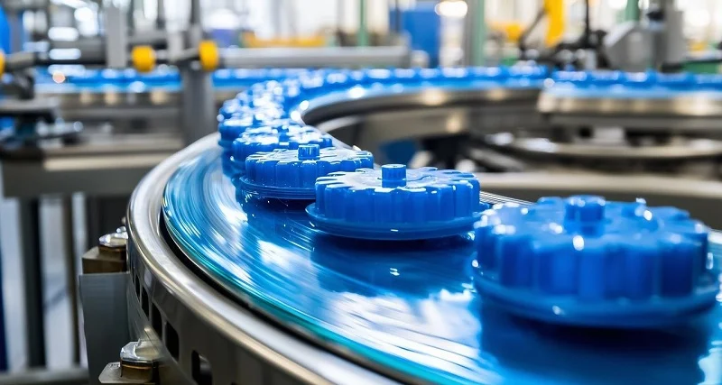
Injection molding forces hot plastic into a steel or aluminum mold. The process repeats thousands of times with the same quality. It is the standard way to make large numbers of diagnostic devices.
High-Volume Cost Efficiency
Once the mold is paid for, the cost per part drops a lot. A single mold can make millions of parts. The cycle time for a typical cartridge is under 30 seconds. This speed makes injection molding the cheapest option for large runs. The cost per part can go below a few cents. This low cost is key for commercial diagnostics that sell in high volumes. The numbers favor molding when you make over 100,000 parts per year. Making each part the same across millions of cycles is a big plus. Each part matches the next within tight tolerances.
Tooling Investment and Lead Times
The upfront cost is the main downside. A multi-cavity mold for a complex part can cost $50,000 to $200,000 or more. Lead times range from 8 to 16 weeks to make the tool. This investment requires you to be sure of the design. Changes after starting the mold are expensive. Designing for manufacturability is very important at this stage. The material choice must also fit the molding process. Some plastics flow better than others. Shrinkage rates vary and affect final sizes. Careful planning reduces these risks. The mold phase needs a full commitment to the design. This method works best when the diagnostic device is final and tested.
3D Printing for Rapid Prototyping
3D printing builds parts layer by layer from a digital model. It removes many limits of traditional manufacturing. This freedom makes it great for early development.
Stereolithography (SLA) and Micro-SLA
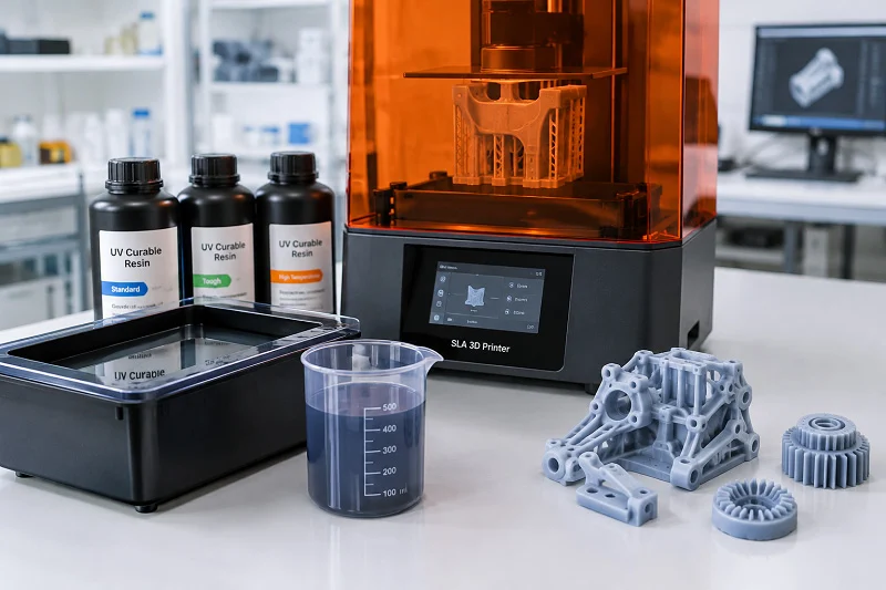
SLA uses a laser to harden liquid resin into solid layers. Micro-SLA pushes this detail to the micron scale. Channel widths below 100 µm are possible. This ability is useful for lab-on-a-chip prototypes. Engineers can test fluid behavior in realistic shapes before paying for production molds. Turnaround time is measured in days. This speed speeds up the design cycle. Teams can test many versions in a single week. The method supports quick exploration of microfluidics designs.
Material Limitations and Post-Processing Needs
The main limit is material choice. Most SLA resins do not have the chemical resistance and biocompatibility of injection-grade plastics. They may absorb water or leak uncured monomers. These issues affect test results in real diagnostics. Post-processing adds extra steps. Parts need cleaning, UV curing, and support removal. Surface finish is rougher than machined or molded parts. This roughness can change flow patterns in microfluidics. For functional testing, these limits matter. For checking shape and fit, they are okay. The technology is getting better. New resins offer better properties. But for production, molding is still the standard. 3D printing serves as a bridge between idea and production.
Common Materials for IVD Fluidic Components
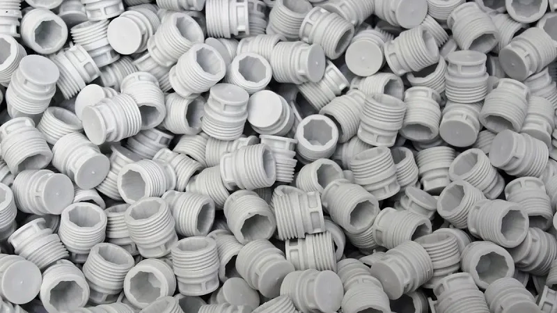
Material selection drives both performance and manufacturing scale. The chosen polymer, elastomer, or metal determines which fabrication process works best. It also affects cost per unit and production volume. Custom tubing, filters, and closures must align with the same material strategy. A mismatch between material and process leads to defects, delays, and failed validation runs.
Polymers: The Industry Standard
Polymers dominate IVD fluidic components because they offer design freedom, optical clarity, and cost efficiency. They mold well at scale and resist common reagents. Most commercial diagnostic cartridges rely on thermoplastic polymers for these reasons.
Cyclic Olefin Copolymer (COC) and Cyclic Olefin Polymer (COP)
COC and COP deliver exceptional optical clarity and low autofluorescence. These properties matter for fluorescence-based detection systems. They also exhibit low water absorption, which keeps dimensional stability tight in humid environments. Both materials resist acids, bases, and alcohols commonly used in extraction protocols. COC and COP flow well during injection molding, allowing thin walls and fine channel features. Their glass transition temperatures are high enough for PCR thermal cycling. This combination makes them the preferred choice for microfluidics chips and optical cuvettes.
Polycarbonate (PC) and Polymethyl Methacrylate (PMMA)
Polycarbonate offers high impact strength and heat resistance. It withstands repeated autoclaving cycles without warping. PC works well for housings, manifolds, and structural frames. Its optical clarity is good, though slightly lower than COC. PMMA provides excellent transparency and surface hardness. It machines easily and polishes to a smooth finish. PMMA suits low-cost, single-use devices where budget constraints dominate. Both materials bond well with adhesives and laser welding. However, PC resists some solvents poorly, and PMMA can crack under stress. Designers must verify chemical compatibility with assay reagents early.
Elastomers for Flexible Components
Elastomers provide the flexibility needed for moving parts. They seal, bend, and compress without permanent deformation. These materials enable valves, pumps, and gaskets to function reliably over thousands of cycles.
Silicone and Thermoplastic Elastomers (TPE)
Silicone offers broad temperature resistance and biocompatibility. It remains flexible from freezing to autoclave temperatures. Silicone also resists oxidation and many chemicals. TPEs combine rubber-like elasticity with thermoplastic processing. They mold faster than silicone and require no curing step. TPEs recycle easily and bond well to rigid plastics through overmolding. Both materials suit high-volume production. Silicone works best for compression seals and diaphragms. TPEs excel in integrated valve structures molded directly onto cartridges.
Role in Valves, Seals, and Diaphragms
Valves rely on elastomer compression to open and close fluid paths. Seals prevent leakage between mating surfaces. Diaphragms transfer pressure without allowing fluid contact with actuators. Each function demands a specific durometer and compression set rating. A soft silicone diaphragm provides sensitive pressure response. A firmer TPE seal maintains integrity under higher backpressure. Material choice directly affects the device’s reliability and lifespan. Testing under repeated actuation is essential before finalizing the design.
Metals and Glass for Specialized Applications

Some IVD fluidic components require properties that polymers cannot provide. Metals handle extreme pressure and temperature. Glass offers unmatched chemical inertness and optical purity. These materials serve niche but critical roles.
Stainless Steel for High-Pressure Environments
Stainless steel withstands high pressures and aggressive chemicals. It resists corrosion and maintains dimensional stability under stress. HPLC fittings, syringe needles, and pump pistons commonly use stainless steel. CNC machining produces these parts with tight tolerances. Electropolishing creates a smooth, clean surface that prevents sample carryover. Stainless steel also survives repeated sterilization without degradation. Its higher cost limits use to components where performance outweighs price.
Glass for Optical and Chemical Inertness
Glass provides superior optical transmission and chemical resistance. It does not absorb reagents or leach contaminants. This inertness makes glass ideal for precision cuvettes and reference standards. Glass capillaries enable precise flow control in microfluidics research. However, glass is brittle and difficult to machine. Manufacturing costs run higher than polymer alternatives. Glass suits applications where optical accuracy or chemical purity is non-negotiable. For most commercial diagnostic products, polymers offer a more practical balance.
IVD Fluidic Components Production Considerations

Regulatory Compliance and Quality Management
ISO 13485 and Design Controls
ISO 13485 sets the quality rules for making diagnostic devices. Every maker of fluidic parts must follow design control steps. These steps cover planning, input, output, review, checking, validation, and handoff. Design controls make sure each part meets user needs and rules. The maker must write down every step. Traceability links design choices back to user needs. This paperwork becomes part of the approval package for regulators. Without it, the device cannot be sold.
Validation and Traceability Requirements
Process validation proves that a manufacturing method always makes parts that meet specs. For injection molding, validation includes installation checks, operation checks, and performance checks. Each stage confirms that the machine, the process, and the output meet set standards. Traceability rules cover every batch of raw material. Lot numbers, process settings, and inspection results must link to each finished part. This trace chain helps when defects show up. It also satisfies auditors who check the quality system.
Cost Analysis and Budgeting
Estimating Total Cost of Ownership (TCO)
Total cost of ownership includes tooling costs, per-part costs, and hidden costs like validation runs and inventory storage. For a diagnostic cartridge at 50,000 units per year, the numbers are clear.
| Scenario | Mold Cost | Molded Part Cost | CNC Part Cost | Crossover Volume |
| Simple plastic housing | $5,000 | $0.80/pc | $15/pc | ~350 pcs |
| Medium-complex enclosure | $20,000 | $1.50/pc | $45/pc | ~460 pcs |
| Multi-cavity connector | $35,000 | $0.50/pc | $25/pc | ~1,430 pcs |
| High-precision part | $60,000 | $2.00/pc | $35/pc | ~1,820 pcs |
At 50,000 units, injection molding total cost runs from $95,000 to $160,000 based on complexity. CNC machining for the same volume goes past $2 million. The crossover point for all cases sits below 2,000 parts. Above 5,000 pieces per year, injection molding always wins on cost. This data directly guides manufacturing process choices.
Balancing Quality, Speed, and Cost
Early product development favors speed over cost. Prototyping with CNC machining or 3D printing allows fast design changes. The trade-off shows up later. A rushed move to production tooling can lock in flaws that cost a lot to fix. The right balance depends on the project timeline and risk tolerance. A step-by-step review process helps teams make smart choices. Each review checks design readiness, process ability, and cost readiness before moving forward. Product teams must weigh these trade-offs all the time.
Tooling and Process Development
Transitioning from Design to Production
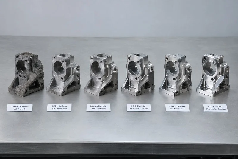
A case study of a diagnostic cartridge shows the key steps. The team used prototype injection molding tools to fix design issues before buying production tools. These prototype parts were assembled using the real manufacturing methods, including ultrasonic welding and laser welding. Fluidic tests were run on the prototypes. Test issues led to several mold changes. Channels, reservoirs, and valve assembly features were adjusted. All issues were fixed before investing in multi-cavity, hardened steel production tools. This method ensures repeatability in the final product.
The following steps guide a successful transition:
- Define target production volumes and costs early. Set a clear path from the start. Manufacturing limits tie directly to early cost choices.
- Select materials with end-production in mind. Find low-volume prototyping methods that let you test the final material. Avoid changing materials between stages.
- Engage manufacturers early for Design for Manufacturability. Bring them in during prototyping. Learn design rules for gate placement, draft angles, and wall thickness.
- Use intermediate-scale tooling as a bridge. Use soft tooling for near-production validation. This reveals hidden material issues before buying hardened steel tools.
- Plan for backend process automation. Backend processes often drive cost and speed. Build and test these processes early.
Ensuring Repeatability and Quality
Repeatability depends on process control. Statistical process control tracks key parameters during production. Temperature, pressure, and cycle time must stay within set limits. Regular sampling and measurement confirm that parts meet specs. Capability indices like Cpk measure process performance. A Cpk above 1.33 shows a capable process. Above 1.67 shows excellent control. These numbers assure that every device leaving the line works as intended.
Decision Framework for IVD Fluidic Components Manufacturing
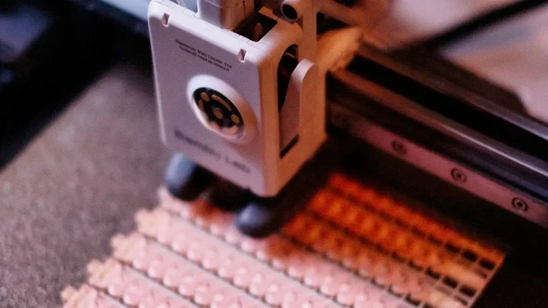
Choosing a way to make parts needs a clear plan. Going by gut feeling alone leads to expensive errors. This guide shows three simple steps. Each step builds on the last one. Together they turn a rough idea into a smart choice based on facts.
Define Your IVD Fluidic Components Requirements and Specifications
First, you must be clear. You cannot pick a manufacturing method without knowing what you need. This step makes you write down every need. It also helps you tell apart must-haves from nice-to-haves.
Creating a Detailed Part Specification Sheet
A detailed part spec sheet is the one source of truth. Every choice comes from this document. It stops your team and partners from misunderstanding each other. The sheet must include more than just sizes. It must include:
- Rules for material approval
- Settings for key sizes
- Rules for surface smoothness
- Standards for part cleanliness
- Needs for consistent assembly
- Checks for first production run
- Rules for tracking each part
- Steps for handling design changes
Each item on this list matters. Material approval makes sure the plastic or metal meets safety rules. Key size settings show which features need exact measurements. Surface smoothness rules set the allowed roughness. Part cleanliness standards stop contamination of patient samples. Assembly consistency makes sure every unit works the same. First production run checks verify the start of making. Production tracking links each part back to its raw material batch. Change management controls how design updates move through the system.
Prioritizing Needs (Must-Haves vs. Nice-to-Haves)
Not every need is equally important. Some features cannot be given up. Others can change without breaking the device. Make two lists. The first list has must-haves. These include meeting rules, being safe for the body, and key size limits. The second list has nice-to-haves. These might be a certain look or faster cycle times.
This sorting matters when talking about cost. A nice-to-have that adds 30% to tooling costs may not be worth it. A must-have that makes sure the test works right is always worth the money. Write down the reason for each priority. This paperwork helps when talking to making partners. It also helps when unexpected trade-offs come up during product development.
Evaluate and Shortlist Potential Processes
The second step matches your written needs against what each making method can do. Each method has different strengths. The check must be orderly.
Matching Requirements to Process Capabilities
Make a comparison table. List your must-haves across the top. List possible methods down the side. Score each method against each need. CNC machining is very good at exact sizes and working with many materials. Injection molding wins on cost when making many parts. 3D printing is fast but has limits on materials. The table shows which method fits your priorities.
Think about how many parts you need. The point where machining and molding cross over is below 2,000 parts. Above 5,000 parts per year, injection molding is always cheaper. These numbers help you make a short list. A low-volume lab device may never need a mold. A commercial test cartridge for millions of units needs molding from the start.
Conducting Feasibility Studies and Prototyping
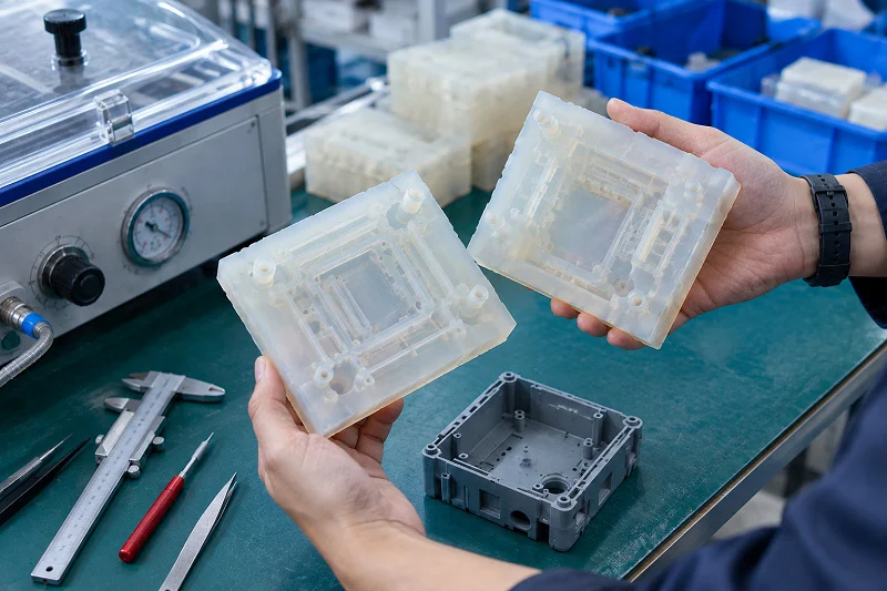
Making test parts checks your ideas before spending money on expensive molds. Enplas describes a microfluidics method where key features are made and tested in as little as two weeks. This happens before spending on a full test mold. The method checks real-life performance and stops costly fixes later.
Protoshop shows a case study of an IVD cartridge that needed a valve part. The challenge was how to put it together: fasteners, ultrasonic welding, or laser welding. Test injection molding checked both the main function and how easy it was to make. This approach helps check if IVD fluidic designs can be made. It finds problems early. It also confirms the chosen method before full-scale investment.
Partner with a Manufacturing Expert
The third step brings in outside help. A contract maker has experience from many projects. That experience saves time and money.
The Value of Early Collaboration
Working with a maker early shortens the start-up time. It lowers later costs and saves time. Design flexibility grows when experts review designs before they are final. The partner makes sure the part works with the whole device. Fluidics and other systems can be developed at the same time. Technical problems get found and fixed early.
A making partner also knows about rules. They know what paperwork inspectors expect. They understand validation steps. They have seen common failure modes in many diagnostic products. This knowledge stops you from repeating mistakes others have already solved.
Requesting Quotes and Evaluating Proposals
Ask for quotes from several partners. Give each one the same spec sheet. This makes sure you can compare proposals. Look at more than just price. Look at lead times, quality systems, and how fast they reply to questions. Ask about their experience with similar diagnostic systems. Ask if they can handle your expected volume.
Check the proposal against your must-have list. Does the partner have the needed certifications? Can they meet your tracking needs? Do they have experience with your chosen material? The cheapest quote rarely gives the best result. The right partner balances cost, quality, and trust. This choice shapes the whole IVD system design. Choose wisely.
Partnering with NOBLE for Your IVD Fluidic Components Project

NOBLE is a top Chinese manufacturer known for great service and skilled processing. The company helps customers move from fast prototyping to full production. This teamwork lowers risk and speeds up timelines for IVD fluidic components development.
Full Capabilities in Metal and Plastic Processing
From Design and Engineering to Assembly
NOBLE offers many services. The team starts with design review and engineering help. They check your part specs against real manufacturing limits. This early teamwork finds issues before tooling starts.
The company also handles assembly. Complex IVD fluidic components often need several parts joined together. NOBLE manages ultrasonic welding, laser welding, and adhesive bonding in-house. This setup removes the need for many vendors. It also cuts down on handling damage and quality control gaps.
Skills in CNC Machining, Injection Molding, and More
The factory has CNC machining centers for prototypes and small production runs. These machines hold tolerances down to ±5 µm for key features. Injection molding presses handle large production runs with ease. The team also does extra steps like surface treatment and cleaning.
This dual skill matters for product development. Teams can test designs with machined parts. They then switch to molded parts without changing suppliers. The same engineers who know your design watch over both processes. This consistency keeps the design intent and lowers miscommunication.
Certifications and Quality Assurance
ISO 9001:2015 and ISO 13485:2016 Certified
NOBLE holds two key certifications that matter for diagnostic device makers:
- ISO 9001:2015 – Focuses on ongoing quality improvement and customer satisfaction.
- ISO 13485:2016 – Keeps a strong quality system for medical device safety and regulatory compliance.
The FDA QMSR Final Rule confirms the value of ISO 13485. As of February 2, 2026, this standard is officially part of 21 CFR Part 820. This change confirms its regulatory importance for IVD manufacturing.
The ISO 13485 quality system is actively used to ensure proper quality control for microfluidic structures, sensor builds, and cleanroom work – all critical elements in IVD fluidic component manufacturing. The certified shop applies these standards at every production step, including factory setup testing, project risk control, and full component traceability.
Commitment to Regulatory Compliance
The quality team tracks changing rules across global markets. They prepare documents that support your regulatory submissions. This includes material certificates, inspection reports, and process validation records. Each batch of parts has full traceability back to raw materials.
This commitment cuts your workload. You get complete documentation packages ready for auditors. The team also supports design control activities required by ISO 13485. They join design reviews and risk assessments when needed.
A Full-Service Partnership from Concept to Production
Supporting Every Stage of Development
The partnership starts with concept talks. Engineers review your needs and suggest material options. They recommend process choices based on volume forecasts and tolerance needs. This guidance helps you avoid costly mistakes.
During prototyping, NOBLE makes test parts quickly. You check fluid flow, chemical compatibility, and assembly methods. Feedback loops stay short. Design changes move through the system without delays. This speed speeds up product development cycles a lot.
Ensuring a Smooth Path to Market
The move from prototype to production goes smoothly. The same team handles both phases. Tooling designs use lessons learned from prototype testing. Process validation follows set protocols. First article inspections confirm that production parts match approved specs.
NOBLE manages the whole supply chain. Material sourcing, inventory management, and logistics all sit under one roof. This single-point accountability lowers coordination overhead. Your team focuses on assay development and clinical validation. NOBLE handles manufacturing complexity.
The result is a smooth path to market. IVD fluidic components arrive on time, within budget, and fully compliant with regulatory rules. This partnership model turns manufacturing from a risk into a competitive edge.
Material choice, dimensional precision, production volume, cost, and regulatory rules shape the manufacturing decision for IVD fluidic components. Each factor connects to the others. A material with excellent optical clarity may require a process that raises unit cost. Tight tolerances demand tooling that increases lead time. The correct process depends on the specific requirements of the IVD system design. No single method works for every diagnostics project. A structured approach prevents costly mistakes. Early collaboration with a manufacturing partner catches issues before tooling starts. This teamwork saves time and money. Contact NOBLE for a consultation. Discuss your project and receive tailored guidance on process selection.
FAQ
What is the cost crossover point between CNC machining and injection molding?
The crossover point is below 2,000 parts for most shapes. If you make more than 5,000 parts per year, injection molding is always cheaper. A simple plastic housing crosses over at about 350 parts. High-precision parts cross over near 1,820 parts.
What tolerances can CNC machining hold for IVD fluidic components?
CNC machining can hold tolerances down to ±5 µm for important features. Standard fine turning or milling gives surface finishes of Ra 0.4 µm. Precision grinding reaches Ra below 0.1 µm. Mirror grinding and polishing reach Ra 0.05 µm for optical surfaces.
Which polymers work best for optical detection in diagnostic devices?
COC and COP give excellent optical clarity with low autofluorescence. These materials work well for fluorescence-based detection systems. Polycarbonate offers good clarity with higher impact strength. PMMA provides great transparency at lower cost. Each polymer flows well during injection molding for thin-wall channel features.
How does ISO 13485 certification affect IVD fluidic components manufacturing?
ISO 13485 sets quality rules for making diagnostic devices. The FDA QMSR Final Rule adds this standard to 21 CFR Part 820 starting February 2, 2026. Certified makers keep design controls, process validation, and full traceability from raw materials to finished parts.
When should I use 3D printing instead of injection molding?
Use 3D printing for early prototypes and design testing. Micro-SLA can make channel widths below 100 µm. Turnaround takes days instead of weeks. However, SLA resins lack the chemical resistance and biocompatibility of injection-grade plastics. Save 3D printing for form and fit checks, not functional testing.
What surface finish do patient-contact IVD fluidic components require?
Patient-contact surfaces usually need Ra 0.4 µm with electropolishing or passivation per ASTM standards. Standard machining can reach this value. Smoother finishes below Ra 0.1 µm need precision grinding. Mirror finishes at Ra 0.05 µm need mechanical polishing plus electropolishing.
How early should I engage a manufacturing partner?
Engage a manufacturing partner during prototyping. Early teamwork shortens startup time and lowers costs. Partners review designs before finalization, catching manufacturability issues early. They know regulatory expectations and common failure modes. This teamwork prevents expensive redesigns after tooling begins.
What backend processes drive IVD fluidic components production costs?
Bonding, surface changes, and reagent deposition often cost more than polymer molding. Electrode printing can add up to 10 times the original molding cost. Plan for backend process automation early. These steps often determine overall production speed and total cost per device.