Introduction
Have you ever encountered this situation: The program runs smoothly, the toolpath is correct, and measurements taken on the machine tool meet specifications. However, once the part is removed from the machine, one corner curls up, and the center section bends. The workpiece ends up having to be scrapped.
This guide will analyze the root causes: which shapes are most susceptible, which materials are most likely to cause problems, and, most importantly, which solutions are truly effective in real-world shop floor operations.
The 5 Root Causes of Warping in CNC Machining
Why do CNC parts warp? Five reasons. Let’s go through them.
1. Residual Stresses from Material Manufacturing
The stock material comes with hidden baggage. Rolling, forging, extrusion—these processes lock internal stresses into the metal or plastic. The forces balance each other inside the block. The part sits flat.
When CNC machining begins and material is removed, this balance is disrupted. Residual stresses are released. The part begins to move. It will warp and bend.
CNC machining acts as a stress-release event. The part simply responds to what was already there.
2. Heat-Induced Expansion (Thermal Effects)
Cutting generates heat. This heat is distributed unevenly and is difficult to predict.
The tool rubs. The chip carries heat away—or does not.
Different parts of a component heat up at different rates. Materials at high temperatures expand, while those at low temperatures do not. This difference in expansion creates internal stress.
The situation is even worse in thin-walled sections. These areas contain less material and are unable to effectively absorb and dissipate heat. As a result, they heat up faster, expand more dramatically, and experience more severe deformation.
3. Clamping/Workholding Forces
The part was placed flat in the vise and clamped securely. Everything looked normal during CNC machining.
After machining was complete, the clamps were released. The workpiece sprang back to its natural shape. At this point, the shape was no longer flat.
This is elastic deformation. During the cutting process, the clamping force causes the workpiece to bend. The CNC machine processes this bent shape. When the clamping force is removed, the workpiece returns to its original non-flat state. Over-clamping a thin ring is a classic example. It is circular when removed from the machine, but immediately springs back into an elliptical shape.
4. Low Workpiece Rigidity
Some parts are just floppy. Long thin walls. Large flat floors with no support. The cutting tool pushes down. The material pushes back, but not hard enough. It deflects.
The tool cuts out this deformed shape. Then the tool continues to move. The material springs back into place. At this point, the bottom surface is no longer flat, and the side walls are no longer straight.
The key lies in this ratio: stiffness divided by cutting force. If this value is low, warping is almost inevitable in CNC machining.
5. Improper Toolpath & Cutting Strategy
Improper programming can cause workpiece deformation; after all, a CNC machine is not a human—it simply follows instructions.
Excessive cutting depth increases cutting forces. Up-cut versus down-cut milling—the wrong choice can increase stress. A lack of buffer cuts means the workpiece has no chance to stabilize. The rough-machined surface is uneven. Finishing removes material from only one side. Stress imbalances become immediately apparent.
These five causes do not act in isolation but compound one another. When stressed material is machined at high temperatures, clamped too tightly, and the workpiece itself is prone to warping—all compounded by poor path planning? Such a workpiece is doomed to fail. This is why
8 Shapes That Are Prone to Deformation
Some shapes are particularly prone to warping during CNC machining. Designers should therefore avoid these shapes from the outset.
| Shape | Primary Failure Mode | Quick Fix |
| Thin Walls & Ribs | Bowing, vibration marks | Support tabs, reduced radial engagement |
| Thin Floors & Pocket Bottoms | Cupping, spring-up | Leave stock, finish in steps |
| Long Slender Parts (High L/D ratio) | Twisting, banana shape | Flip part, stress relief cycles |
| Large Flat Thin Plates | Doming, edge lift | Vacuum fixture, climb milling only |
| Asymmetric C-Shape or U-Shape Parts | Legs spreading or closing | Clamp after roughing, rest passes |
| Thin Flanges & Overhangs | Droop, chatter | Back up with soft jaws, reduce stickout |
| Thin-Walled Tubes & Cylinders | Ovaling, tapered walls | Mandrel support, balanced cuts |
| Parts with Deep Pockets | Floor warping, wall lean | Helical ramping, rest finishing |
Now let’s look at each shape in more detail. Understanding which CNC shapes are prone to warping helps catch problems before programming starts.
Thin Walls & Ribs
Such structures are common in aerospace housings and electronic enclosures—tall walls with relatively thin walls. Cutting forces push them sideways, causing vibration and bending.
Thin Floors & Pocket Bottoms
When a tool cuts a groove, the base at the bottom is thin and has no support beneath it other than air. Cutting forces act downward, causing the base to flex. After the tool passes, the base springs back to its original position. The result is that the base is no longer flat.
Long Slender Parts (High L/D Ratio)
Imagine a long shaft or a slender beam. During machining, the part bends under its own weight. It deflects away from the tool. The material removal is less in the middle than at the ends. The finished part ends up looking like a banana.
Large Flat Thin Plates
A large, flat sheet may seem simple, but it is not. Residual stresses in the raw sheet or blank are released unevenly. The edges may curl up, the center may bulge, and eventually the entire workpiece may warp.
Asymmetric C-Shape or U-Shape Parts
These shapes are open on one side. The two “legs” are not connected at the open end. Clamping force pushes the two “legs” inward to complete the cut. When the clamping force is released, the legs spring back, altering the dimensions at the opening.
Thin Flanges & Overhangs
This feature protrudes outward and is supported on only one side. Cutting forces apply downward pressure on the free end, causing the flange to sag, resulting in chatter and extremely poor surface finish.
Thin-Walled Tubes & Cylinders
Thin-walled circular parts are deceptive. After the outer surface is machined, stress is released, causing the circle to stretch and deform into an ellipse, or, due to the part flexing away from the tool, the wall thickness becomes uneven.
Parts with Deep Pockets
Deep cavities result in a long tool overhang. While the tooltip may flex, the real issue lies with the remaining bottom and side surfaces. Uneven cutting causes imbalance, leading to warping of the bottom surface and tilting of the side walls.
Recognizing these shapes early is the first defense against CNC machining warping. Each one needs a different strategy. The quick fixes in the table get started.
Materials That Demand Extra Attention
Some are stable. Some are not. Knowing which materials warp in CNC machining saves a lot of scrap.
Aluminum (6061-T6, 7075-T6) – Rolling Stress
The rolling process generates internal stresses in aluminum. As the aluminum sheet is squeezed between the rollers, the surface is subjected to tensile stress, while the core remains under compressive stress. At this point, the workpiece is flat. Subsequently, machining removes material from one side of the workpiece. The balance breaks. The part warps immediately.
Stainless Steel Sheets (304, 316) – Work Hardening
This material hardens when it is cut. The surface layer stiffens. The core does not. This differential hardness creates differential stress. Thin stainless steel parts are notorious for twisting off the machine.
Titanium (Grade 5) – Low Stiffness + Spring-Back
Titanium has a low modulus of elasticity. That is a fancy way of saying it bends easily and springs back hard. Cutting pressure deflects the part. The tool cuts the deflected shape. Then the part springs back to a new, wrong shape. CNC machining with titanium is a daily battle.
Hardened Tool Steels – Heat-Induced Phase Change
Heat from cutting can change the microstructure. The surface transforms. The volume changes slightly. That small change creates large stress. The part pulls. It twists. Hardened steel does not announce this problem. It just shows up as a warped block after finishing.
Brass & Free-Cutting Copper – Extrusion Stress
These materials are often extruded. The extrusion process locks in a grain direction and internal stress. Machining breaks that stress unevenly. The part moves. Sometimes it moves a lot.
Plastics (Nylon, Acetal, UHMW) – Heat & Creep
Plastics are worse than metals. They conduct heat poorly. The cutting zone gets hot. The surrounding material stays cool. That temperature difference creates stress. Then the part creeps over time. It sits on the inspection table. It measures fine. An hour later, it is warped. This is why CNC parts warp in plastic more often than operators expect.
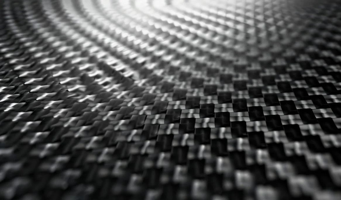
Carbon Fiber Composites – Anisotropic Stress
The fibers go in one direction. The matrix holds them. Stress in the part is not the same in all directions. Machining cuts through fibers. The remaining structure reorganizes its stress. Thin composite parts twist in unpredictable ways.
Magnesium Castings – Non-Uniform Cooling Stress
The casting cools. The outside solidifies first. The inside solidifies last. The core pulls against the skin. That locked-in stress waits for machining. Remove enough material, and the balance tips. The casting warps.
An unstable one requires stress relief, different toolpaths, or both. Ignore the material properties, and CNC machining warping becomes inevitable.
How to Prevent Warping – Practical Strategies
Not only is repairing warped parts troublesome, but it is also costly. Taking steps to prevent problems before they arise can help us save time and effort. Here is how to stop CNC warping at each stage of the job.
Before Machining: Material Prep
Materials typically arrive with residual stresses. These stresses must be relieved before cutting.
The thermal stress relief method involves placing the workpiece in an oven. It is heated, held at a constant temperature, and then slowly cooled. This allows the internal stresses to be released. The vibration stress relief method involves subjecting the workpiece to vibrations. The amplitude is small, just enough to allow the atoms to rearrange themselves. Cryogenic treatment utilizes extremely low temperatures. The material contracts uniformly, thereby balancing the residual stresses.
Controlling the rough machining dimensions of the blank also helps relieve stress. A large blank is rough-machined to near-final dimensions, allowed to rest for a period to undergo natural deformation, and then finished. This deformation occurs during the resting period of the blank, rather than during the machining of the finished product.
Workholding & Fixturing
Clamping force is a double-edged sword. If the clamping force is too low, the workpiece will shift during machining; if it is too high, the workpiece will undergo elastic deformation. When the clamping force is released, the workpiece will spring back and become warped.
Low-force clamping is the solution. Apply only enough force to secure the workpiece—never more than necessary.
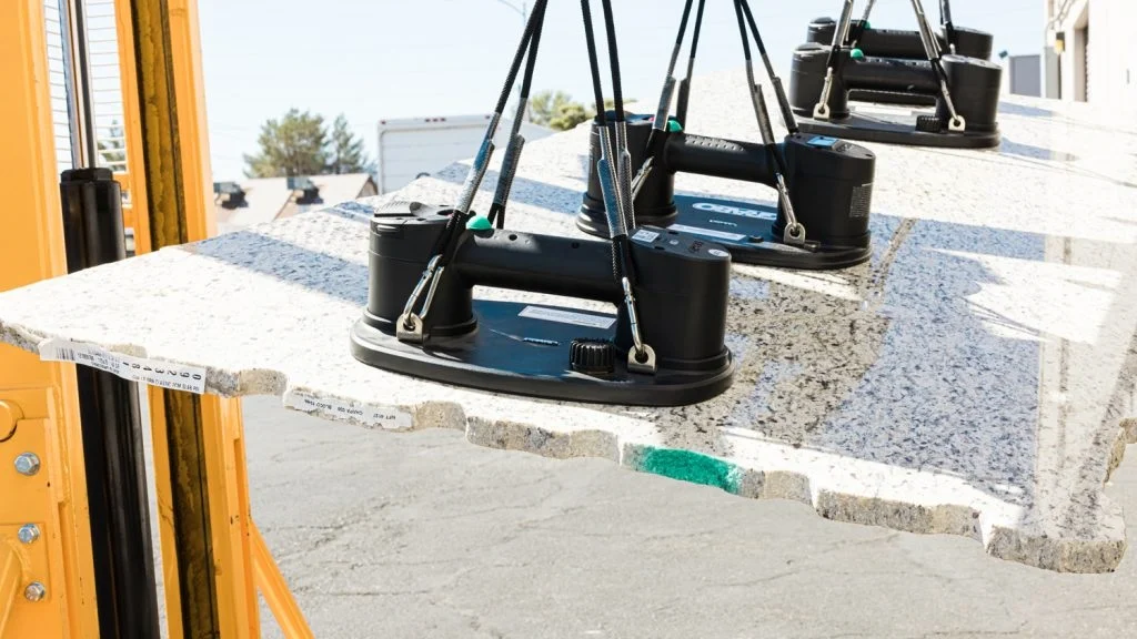
Vacuum cups are suitable for flat workpieces. They provide uniform suction without creating localized pressure points. The soft suction lips conform to the shape of the workpiece, distributing the force over a larger area. Embedding wax is suitable for precision or irregularly shaped workpieces. The workpiece is embedded in the wax and held in place by it, eliminating the need for any clamping force.
Toolpath Strategies
The sequence matters more than the individual cuts.
Rough the part first. Leave stock on all surfaces. Then, stress relieve the part. Then finish it. The roughing releases the bulk of the internal stress. The stress relief step handles the rest. The finishing cut removes only a thin layer. That layer does not carry enough stress to cause CNC machining warping.
Adaptive or trochoidal milling changes the game. The tool takes a light radial cut. It moves in a circular path. Chip thickness stays constant. Cutting forces stay low. Heat stays low. The part does not deflect.
Climb milling versus conventional milling? Climb milling pushes the tool into the part. Conventional milling pulls the tool away. For warping prevention, climb milling wins. Cutting forces go downward, into the table. Not sideways, into the thin wall.
Cutting Parameters & Cooling
Coolant removes heat. It also creates thermal shock. The cutting zone gets hot. The coolant hits it. The surface cools fast. The core stays hot. That temperature difference creates stress. An air blast removes chips and provides some cooling without the shock.
Avoid thermal cycling. Do not let the part heat up, cool down, heat up again. Each cycle adds stress. Keep the cutting conditions steady from start to finish.
Multi-Step Machining
Two setups are better than one when CNC parts warp from uneven material removal.
Flip-cut strategies balance the stress. First, rough-machine one side, then flip the workpiece and rough-machine the other side. Flip it again. Alternate material removal between the two sides at each step. This keeps the stresses balanced.
Sacrificial supports are temporary. Add ribs or lugs to thin-walled areas before machining. Remove the supports during the final pass. The workpiece remains rigid during machining. The supports are cut away, leaving no trace.
These strategies work together. Material pre-treatment reduces initial stress. Proper workpiece clamping prevents elastic rebound. Intelligent toolpaths minimize cutting forces. Adequate cooling controls heat buildup. A multi-step machining sequence balances material removal. Combine them all. That is how to stop CNC warping for good.

NOBLE – Precision CNC Machining & Plastic Machining
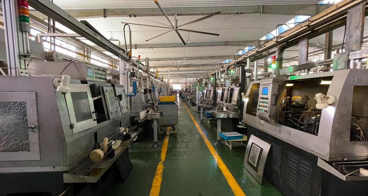
Our Core Processing Capabilities
The shapes and materials from the previous sections? We handle them daily.
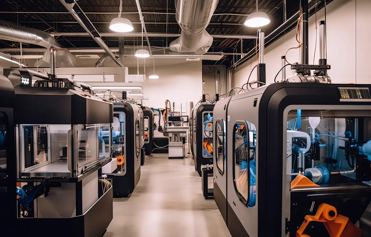
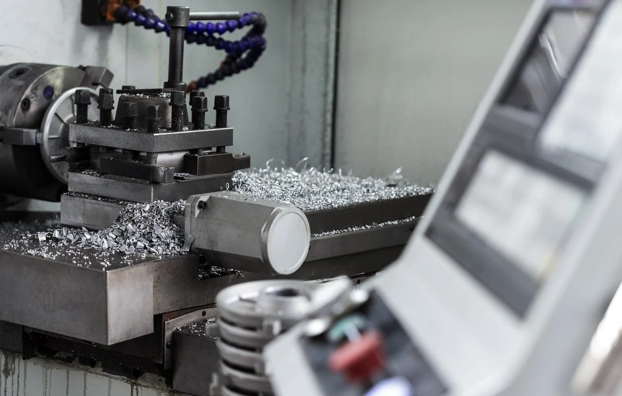
CNC Machining Services
- 3-axis, 4-axis, and 5-axis CNC milling
- CNC turning with live tooling
- Mill-turn for complex one-hit geometries
- Prototyping through full production runs
Plastic Machining Services
- CNC machining of engineered plastics: PEEK, POM, ABS, Nylon, UHMW, PTFE
- Plastic injection molding for higher volumes
- Post-processing: deburring, heat setting, surface finishing
Quality Certifications – Your Assurance Against Warping
| Certification | Scope | What It Means for You |
| ISO 9001:2015 | Quality management system | Consistent processes, documented stress-relief protocols, and traceable inspection |
| ISO 13485:2016 | Medical device quality management | Rigorous process control – critical for implantable instruments and surgical tools where micron-level deformation is unacceptable |
FAQ
Can you fix a warped CNC part after machining?
Sometimes. Press straightening or heat straightening works for ductile metals. But fixing CNC parts that warp after the fact is always more expensive than preventing it in the first place.
Does annealing always prevent warping?
No. Annealing reduces residual stress but does not eliminate it. Uneven material removal after annealing can still cause CNC machining warping.
Is warping worse for 5-axis vs 3-axis machining?
Not inherently. The machine type matters less than the process strategy and stress balance during material removal. Poor toolpath planning causes CNC parts to warp on any machine.
What is the thinnest wall I can reliably machine without warping?
There is no universal number. It depends on material, wall height, cutting forces, and tolerance requirements. For aluminum, a safe starting rule is 1mm thickness for every 20mm of height.