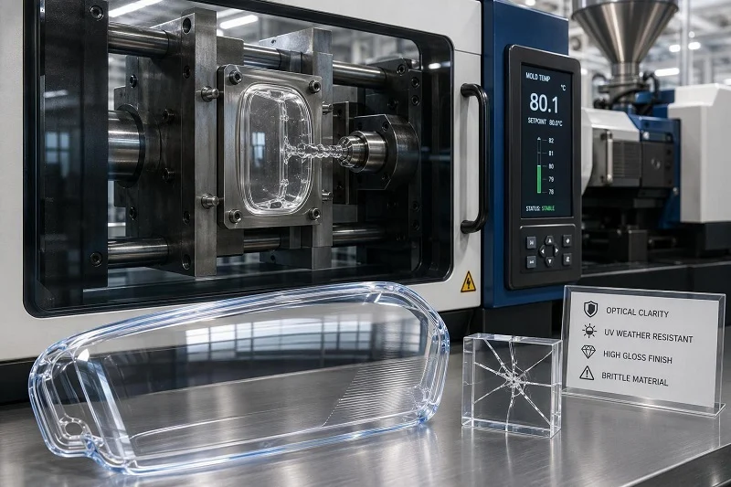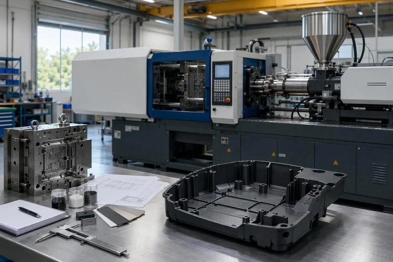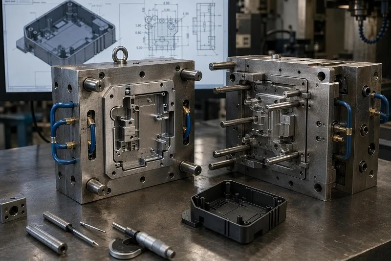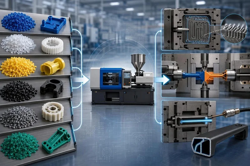
Injection molding is not one process but a family of them. Every member of the family shares the same basic move — a feedstock is plasticized, forced into a closed cavity, and solidified into the shape of that cavity — yet the feedstock chemistry, the machine configuration, the tooling, and the number of materials or stages involved can differ so much that two projects described as “injection molding” may share almost nothing on the shop floor. That is why a useful guide to the types of injection molding process has to organize them along more than one axis.
This guide uses two. The first is material: what is being injected determines how it melts, how it sets, what it does to the screw and barrel, and what happens after the part leaves the mold. The second is technique: some types of injection molding process are defined not by feedstock but by how many materials, inserts, or stages a single part requires. Together the two axes cover the ground a product developer, design engineer, or sourcing team needs in order to narrow a project to a shortlist of candidate processes before any tooling is quoted.
What Are the Types of Injection Molding Process?
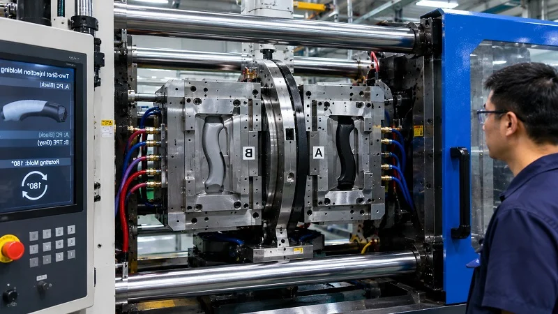
Every type of injection molding process begins the same way. Pellets, granules, or a liquid component are fed into a heated barrel, where a reciprocating screw or a plunger plasticizes the material and builds a shot. The shot is injected under pressure into a closed, cooled or heated cavity, held while the material packs and solidifies, and then the mold opens and the part is ejected. What changes across the types of injection molding process is everything around that core: the temperature of the tool, the chemistry of solidification, the number of injection units, and the post-molding steps the part still needs.
Classification matters because the choice is rarely free. Material chemistry sets the processing window and the tool steel. Part geometry — wall section, flow length, feature size — sets the injection speed and clamp force the machine must deliver. Production volume sets how much tooling investment can be amortized. And the need for multiple materials or embedded components pushes a project toward a special technique rather than a different resin. A process that is ideal at one million parts per year can be uneconomic at five thousand, and a process that handles a micron-scale feature can be the wrong tool for a large housing.
The sections below take the two axes in turn. The material-based classification covers thermoplastics, thermosets, elastomers and liquid silicone rubber, metal and ceramic powders, and composites. The special-process classification covers techniques defined by multi-material or multi-stage construction, from two-shot molding to reaction injection molding. Later sections address how volume, tooling, automation, and part requirements narrow the choice further.
How Types of Injection Molding Process Are Classified by Material
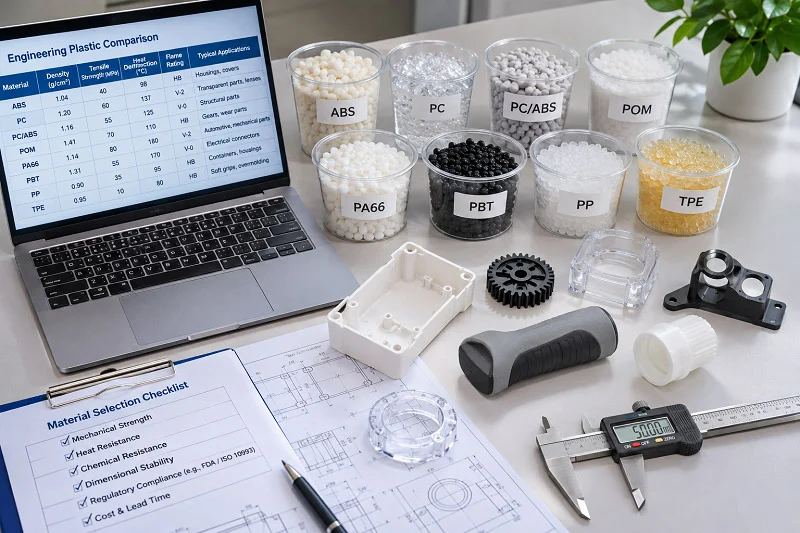
Material is the first-order decision because it constrains everything downstream. Feedstock chemistry determines the machine configuration (screw geometry, barrel and nozzle temperatures, drying requirements), the tooling metallurgy and surface treatment, the cycle profile, and the post-processing steps. The same press can in principle run very different feedstocks, but rarely without changes to the screw, the barrel, the temperature control zones, and the mold steel — and sometimes not at all, as with liquid silicone rubber, which needs metering and mixing equipment a standard thermoplastic press does not have.
The five material families below cover the feedstock landscape for the types of injection molding process. Within each family, grades differ in processing window and properties, but the fundamental mechanism of forming the part stays the same.
Thermoplastic Injection Molding
Thermoplastics are the dominant category and the one most people mean when they say injection molding. The feedstock is a semi-crystalline or amorphous polymer that melts when heated and re-solidifies when cooled, reversibly. The cycle is melt, inject, pack, cool, eject, and the part can in principle be reground and re-molded, though properties degrade with repeated thermal history and the number of safe cycles varies by material.
Shrinkage and warpage are the practical concerns that dominate thermoplastic part and tool design. Differential shrinkage — where shrinkage in the flow direction differs from shrinkage across it — is a primary cause of built-in stress and warpage, and it is driven by material choice, part design, gate location, and processing. Amorphous resins generally shrink less and more isotropically than semi-crystalline ones, which is why they are often preferred when tolerances are tight. Commodity, engineering, and high-performance grades differ in processing window, temperature resistance, and cost, not in the fundamental process.
Thermoset Injection Molding
Thermosets cross-link irreversibly. The feedstock does not freeze on cooling; it cures, usually in a heated mold, and once set it cannot be re-melted or reshaped. That single difference changes the process in several ways. The tool is heated rather than cooled, cycle times are governed by cure kinetics rather than by heat removal, and scrap cannot be reground back into the feed — a cured runner or a rejected part is waste.
The payoff is performance. Cross-linked networks give thermosets their resistance to high heat and aggressive chemicals, which is why they appear in electrical components, high-temperature housings, and chemically exposed parts. The distinction from thermoplastics is worth stating explicitly because it drives tooling and scrap economics: a thermoplastic project can often absorb a bad start-up shot by regrinding it, while a thermoset project cannot.
Elastomer and Liquid Silicone Rubber Injection Molding
Rubber and liquid silicone rubber form a distinct material family with its own equipment. Liquid silicone rubber is a high-purity, platinum-cured silicone with low compression set and stability across extreme temperatures, and because it is thermosetting it requires special handling: intensive distributive mixing while the material is kept cold, then injection into a heated cavity where it vulcanizes.
A typical liquid silicone rubber setup uses metering units that pump the two components — base and catalyst — at a constant ratio, a static mixer that blends them homogeneously, and a cooled metering section on the injection unit. In a cold-deck arrangement, the mixed compound travels through cooled sprue and runner systems into the heated cavity, which minimizes material loss and allows parts with nearly zero valve-gate waste, though a cold runner tool is expensive relative to conventional hot-runner tooling. The combination of purity, biocompatibility, and resistance to bacteria growth is why liquid silicone rubber suits medical, sealing, and other high-purity applications.
Metal and Ceramic Powder Injection Molding
Powder injection molding uses a feedstock of metal or ceramic powder compounded with a multi-component binder. The feedstock is injected into a mold to produce a “green” part, the binder is removed in a debinding step to leave a “brown” part, and the part is then sintered to develop its final density and mechanical properties. The molding step looks familiar; the debinding and sintering steps do not, and they are what make powder injection molding a different proposition in tooling, lead time, and shrinkage control.
The process splits by injection pressure. High-pressure powder injection molding uses feedstocks with viscosities in the range of 100 to 1,000 Pa·s and injection pressures of roughly 20 to 200 MPa, and it has historically been tied to mass production. Low-pressure powder injection molding uses low-viscosity feedstocks built on low-molecular-weight polymers; research has demonstrated it on metals, ceramics, and carbides — including 316-L stainless steel, Inconel 718, alumina, and cemented tungsten carbide — and near-net-shape ceramic parts in the range of 100 to 10,000 units. Low-pressure powder injection molding can therefore serve low or large batch production rates, not only mass production, and it brings a smaller injection machine, fewer debinding steps, and lower manufacturing cost, at the price of a more delicate binder system and more demanding debinding control.
Composite and Fiber-Reinforced Injection Molding
Short-fiber and particulate composites are processed on standard reciprocating-screw presses, but the filler changes the process in ways that matter. Fiber loading raises viscosity, increases wear on the screw, barrel, check ring, and tooling, and introduces anisotropy: shrinkage and mechanical properties differ along the flow direction and across it, which complicates tolerance control. Screw design, back pressure, and screw recovery speed all affect how much fiber length survives the journey to the cavity, and fiber attrition in turn affects the properties of the molded part.
Reinforced reaction injection molding is a related but distinct route: glass or mica fillers are added to a reactive mixture and the result is used for rigid panels, typically in automotive applications. The reinforcement strategy, the machine, and the chemistry differ from compounding fibers into a thermoplastic pellet, so the two should not be treated as interchangeable.
Special Types of Injection Molding Process for Multi-Material and Multi-Stage Parts
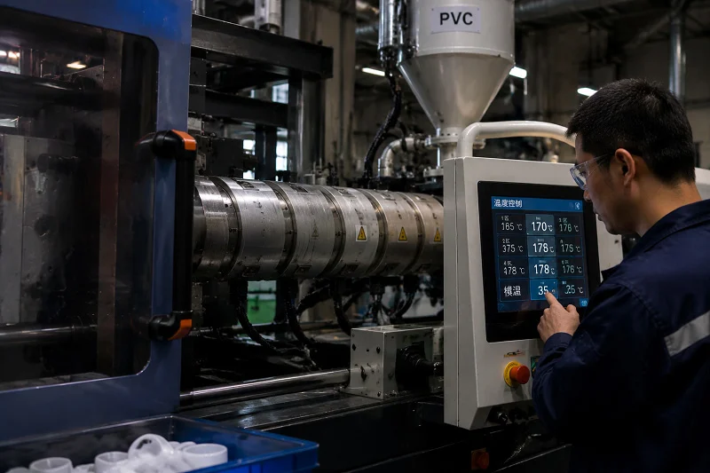
The second axis is defined not by what is injected but by how many materials, inserts, or stages a part involves. These techniques exist because single-shot molding of one material cannot always deliver what a design needs: a soft grip on a rigid housing, a metal thread encapsulated in plastic, a regrind core hidden under a virgin skin, or a micron-scale feature that freezes before it fills. Each special type of injection molding process solves one of those conflicts, and each adds tooling cost, process complexity, or both.
Two-Shot and Multi-Material Molding
Two-shot and multi-material molding inject two materials in sequence on a single machine, with the mold opening, indexing or rotating between shots so the second material is molded against the first. The result is a multi-material part with a chemical or mechanical bond at the interface, produced without a separate assembly step.
The economics decide the choice. Two-shot molding favors large production volumes — typically over 10,000 parts — and certainty about the design and materials for the entire run, because the tooling is costly and changes are expensive. At modest volumes, or when the design may still change, pick-and-place overmolding on a separate press is usually the more sensible route. Bond strength is not guaranteed by the process alone: for some overmolding materials there can be a significant difference in bond strength between multi-shot and insert molding, so material pairing and process route have to be evaluated together.
Insert Molding
Insert molding injects resin around a pre-placed insert, typically metal, so that the insert is encapsulated in the molded part. The approach eliminates secondary insertion steps such as heat staking or ultrasonic welding, and it is generally more controllable and gives better encapsulation than those methods. Molded-in inserts also remove a secondary installation process from the routing, saving time and cost.
The tooling requirement is the catch: the mold must locate and hold the insert against injection pressure so that the resin flows around it without shifting or damaging it. Insert placement is an extra step in the cycle, and automation reduces its impact compared with manual loading. Beyond metal, insert molding can accommodate ceramic inserts for heat resistance and electrical insulation, magnetic components, and electronic modules such as sensors and circuit boards.
Overmolding
Overmolding bonds a second plastic layer onto a molded substrate to add soft-touch grip, sealing, or aesthetic accents. It differs from insert molding in that the substrate is typically plastic rather than a preformed insert, and overmolding itself can be run as two-shot molding in a single machine or sequentially on a separate press with pick-and-place handling.
Bond strength is the central design problem. Acceptable bonding is achieved through a combination of part design, material selection, mold design, and molding process, and the two layers may bond chemically at the interface, mechanically through the interface geometry, or both. Moisture is a quiet failure mode: the moisture level of both the overmold grade and the substrate can adversely affect adhesion, so hygroscopic materials need to be dried before molding. Colorants matter too, since an incompatible carrier in a color concentrate can seriously degrade adhesion.
Co-Injection Molding
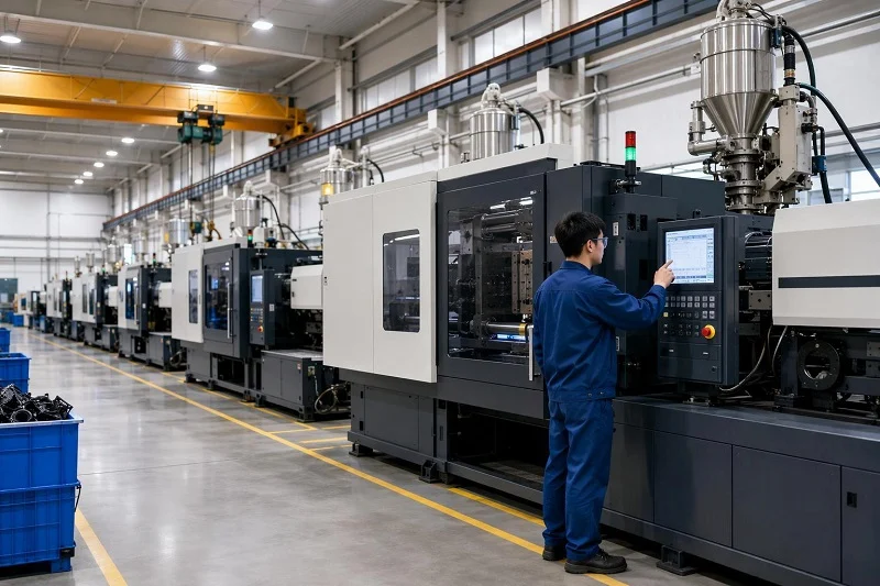
Co-injection molding, sometimes called sandwich molding, injects two dissimilar materials sequentially through two barrels and one nozzle. The skin plastic goes in first, the core plastic follows and displaces the skin at the hot core, and a final skin injection purges the core from the sprue. Fountain flow does the rest: as the cavity fills, plastic at the melt front moves from the center line to the cavity walls and freezes there, leaving the core material in the middle of a sandwich structure.
The rationale is performance per unit cost. Regrind can be used as the core under a virgin skin that preserves surface finish; a thermally more stable core can raise the thermal resistance of the part; a high-melt-flow core can reduce overall clamp force. The process-control challenge is keeping the core from breaking through the skin, which is why co-injection analysis is used to optimize the process strategy before the tool is cut.
Micro Injection Molding
Micro injection molding is built for parts measured in milligrams and features measured in microns — microneedle patches, micro gears, optical connectors, microfluidic chips with channels tens to hundreds of microns wide. Machines based on plunger, reciprocating-screw, and multi-stage designs exist, and the process differs from conventional molding in more than scale: melt and mold temperatures are higher, and injection speed and pressure are higher.
The difficulty is control at very small shot weights. A 1 mg shot needs roughly a 0.0056 mm stroke on a 14 mm screw, and smaller-diameter screws can struggle to maintain injection pressure and feed pellets. Conventional machines are sometimes adapted by making the sprue and runner system around 100 times larger than the micro part so the metering size can be controlled, but that wastes resin, lengthens the cycle, and hides the effect of machine parameters on the part. Variotherm mold heating is the standard answer to premature freeze-off: it reduces viscosity and makes high-aspect-ratio filling feasible, with aspect ratios up to 10 at 40 µm feature thickness demonstrated using a variotherm system.
Gas-Assisted and Water-Assisted Injection Molding
Gas-assisted and water-assisted molding both inject a fluid into the melt to core out thick sections, pack the part, and reduce warpage and weight. Gas-assisted molding allows controlled filling and more uniform distribution of plastic, which reduces deformation, stress, and shrinkage and gives parts with higher dimensional precision and better shape stability.
Water-assisted molding pushes the same idea further. Water has roughly 40 times the thermal conductivity of gas and about four times its heat capacity, and it has brought cooling cycle times down by as much as 70% compared with gas assist, while also producing smoother internal walls — valuable in parts designed to transport fluids or gases. The drawback is that fast cooling against maintained pressure can create voids in the part wall or break through the skin. Materials such as nylon with a fast crystallization rate set up quickly when cold water meets hot melt, so the melt becomes less fluid and less able to accommodate the incoming, incompressible water; the result can be punctured walls, cold slugs, or a marred inner surface. Grades with slower crystallization and higher hydrolysis resistance have been developed for water-assisted molding, and the trade-off is clear: cycle-time and quality gains against added process complexity and control equipment.
Foam and Microcellular Injection Molding
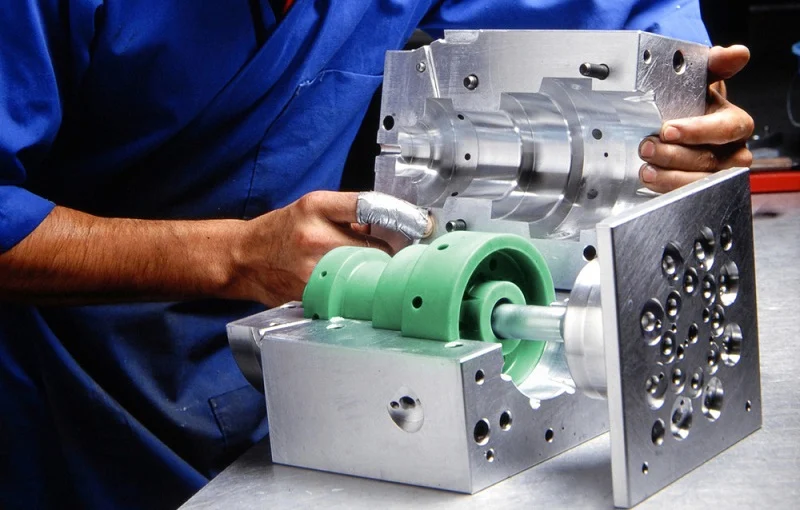
Foam and microcellular molding mix a physical blowing agent — typically a supercritical fluid — into the melt. The dissolved gas reduces melt viscosity, and on injection the pressure drop nucleates a large number of small cells. The microcellular process is reported to allow 30% to 40% material reduction while yielding parts with higher impact strength and an internal structure of small bubbles in the 2 to 10 µm range.
The molded part typically has a sandwich structure of solid skin and foamed core. Mold temperature and cavity pressure are the key factors governing surface quality: a low mold temperature suppresses cell growth near the wall and forms the solid skin, and skin thickness is also influenced by flow rate and cavity depth. Because surface finish is the usual weakness of foamed parts, gas counter-pressure and dynamic mold temperature control are used to improve it, and cavity temperature and pressure sensors support in-line monitoring. The process is sensitive to shot volume, mold temperature, gas dosage, and injection velocity, and cell size can vary region to region within a single part, so mechanical properties can vary with it.
Thin-Wall Injection Molding
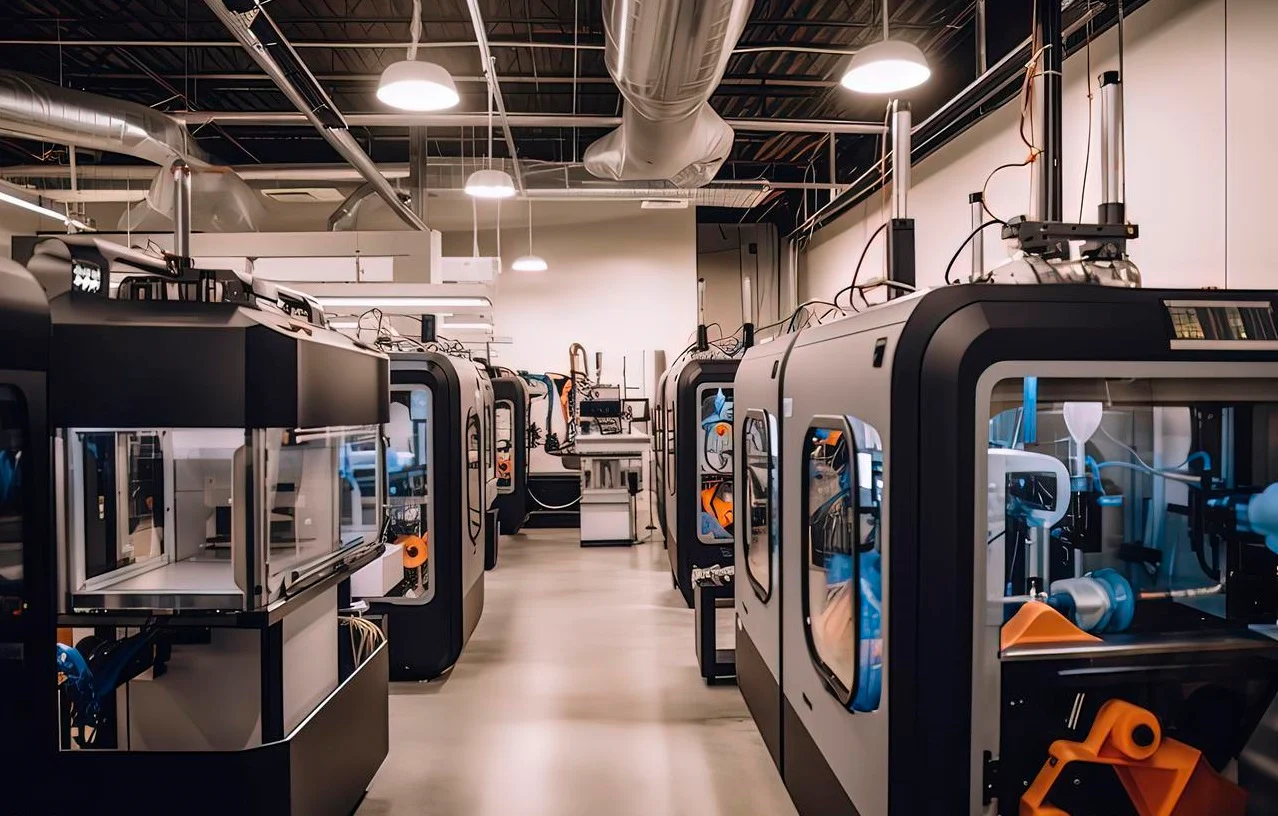
Thin-wall molding is less a separate machine than a regime. A part is generally classified as thin-wall when its nominal wall thickness is under 1.0 mm (0.040 in), or when its flow-length-to-wall-thickness ratio exceeds 150:1 even at a wall of 1.0 to 1.2 mm on a large housing. Filling such a cavity before the melt freezes requires high-speed injection — on the order of 300 to 1,000 mm/s — specific injection pressures around 180 to 280 MPa, and clamp force in the range of 1.0 to 1.5 tons/cm².
The tooling has to be robust enough for that pressure, and gate design has to be chosen so the melt reaches the extremities before the frozen layer closes them off. Thin-wall molding also interacts with micro features: when a cavity has both thick and thin regions, melt hesitates at the entrance of the micro features until the thicker substrate fills, and if the hesitation time exceeds the critical cooling time of the feature, the polymer solidifies at the stagnation point before the feature is full.
In-Mold Labeling
In-mold labeling places a printed label or decorative film, flat or preformed, into the mold — often robotically — so that the injected resin backs it up and fuses it into the part surface during molding. The label becomes an integral part of the part rather than an applied sticker, which gives durable, integrated graphics without a secondary decorating step.
The technique has a long history in standard injection molding, starting with woodgrain automotive interior trim and expanding into preprinted foils and dry-paint films for interior and exterior parts, handheld electronics, and major appliances. The tooling and handling requirements are the practical constraint: the label must be placed and registered precisely, and the handling system has to keep pace with the molding cycle.
Reaction Injection Molding
Reaction injection molding is a distinct chemistry rather than a distinct solid. Two low-viscosity reactive components are impinged and mixed, then injected into a mold where they polymerize. Polyurethane is the most common system, but polyureas, polyisocyanurates, polyesters, polyphenols, polyepoxides, and nylon 6 can also be processed this way.
Because the mixture is much less viscous than a molten thermoplastic, large, lightweight, and thin-walled parts can be molded, and the lower viscosity requires less clamping force — which means smaller equipment and lower capital expenditure. RIM foam also forms a high-density skin over a low-density core. Reinforced reaction injection molding adds glass fibers or mica to produce rigid foam panels, typically for automotive use. Tooling can be machined steel or aluminum, cast aluminum, silicone rubber, epoxy resin, or nickel, and machine size scales with the part.
How Production Volume and Tooling Shape the Choice Among Types of Injection Molding Process
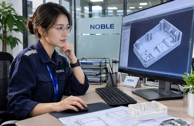
Process selection is also an economic decision, and the tooling is where it shows up. The Plastics Industry Association — formerly the Society of the Plastics Industry — defines five mold classes that give a common language for tooling life. Class 101 is built for over one million cycles; Class 102 for 500,000 to one million; Class 103 for under 500,000; Class 104 for less than 100,000; and Class 105 for prototype work at fewer than 500 cycles. The classes differ in materials and hardness as well as life: Class 101 uses high-grade steel with cavities and cores hardened to a minimum of 48 R/C, while Class 105 is often cast metal and is the least expensive of the five. These classifications are guidelines for quoting and ordering, and they do not by themselves guarantee workmanship.
Cavity count is the second lever. Below roughly 50,000 parts per year, one- or two-cavity tooling is the usual starting point, because a higher cavity count rarely pays back in the short run. The break-even point at which a multi-cavity mold recovers its extra investment over a single-cavity tool usually lies between 50,000 and 200,000 parts, depending on part size, material cost, and machine rate. Those figures are typical guidance, not universal rules: a large part with expensive resin and a high machine rate can justify multi-cavity tooling at a different volume than a small commodity part.
Volume also interacts with the material and special-process choices above. A thermoset project cannot regrind its start-up scrap, so low-volume runs carry a different cost structure than a thermoplastic run of the same size. A two-shot tool carries a higher up-front cost that only a large, design-stable program can absorb. And a Class 105 prototype tool is the natural way to prove a design before committing to a Class 103 production tool.
How Automation and Process Control Differ Across Types of Injection Molding Process
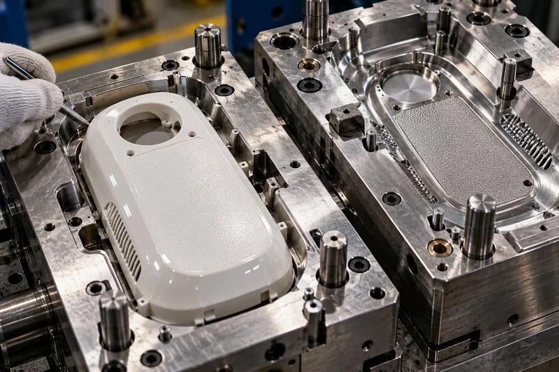
The control and automation layer varies as much as the process itself. Conventional molding relies on closed-loop injection and clamp control, cavity-pressure sensing, and mold temperature control; the special processes add control axes on top of that. Variotherm systems heat and cool the mold on a controlled cycle to manage filling and surface quality. Gas and water injection require dedicated control units that time the fluid injection, hold, and relief. Liquid silicone rubber needs metering and mixing control to hold the two-component ratio. Insert molding and in-mold labeling need robotic placement and registration that keeps pace with the cycle.
The common thread is that sensor data supports in-line monitoring and validation of simulation. Cavity pressure and temperature sensors placed in the mold provide the data to check that the process is running as modeled, and simulation tools are used to optimize mold design and process settings before the tool is cut. The limits are worth knowing: current microcellular simulation tools cannot accurately capture the entire injection process because of large pressure variations, high cooling rates, and complex nucleation, and they assume uniform cell nucleation, so cell shape and its effect on anisotropy are not captured. Simulation narrows the search; it does not replace the trial.
How to Select the Right Type of Injection Molding Process for Your Part
A practical selection sequence moves from part requirements to process in a fixed order, because each step constrains the next.
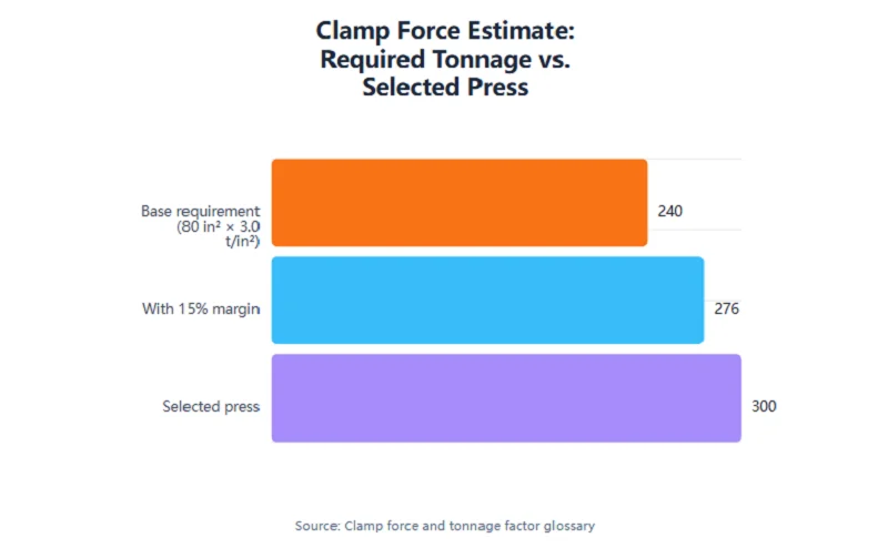
Worked clamp-force screening estimate for an ABS-class part: 80 in² projected area (parts, runners and sprue) × 3.0 tons/in² empirical factor = 240 tons, plus a 15% margin = 276 tons, pointing to a roughly 280–300 ton press. The factor is a screening value for general engineering resin and must be validated with cavity-pressure data or mold-flow analysis.
Start with the material family. Thermoplastic, thermoset, elastomer or liquid silicone rubber, metal or ceramic powder, and composite each point to a different machine and tooling set, and the choice is usually driven by temperature, chemical exposure, purity, or mechanical requirements rather than by the molding process itself.
Then look at geometry and wall section. Thin walls, long flow lengths, and micro features push toward high-speed, high-pressure regimes and variotherm tooling; thick sections may point toward fluid-assisted or foam processes that core out the interior.
Then ask whether the part needs more than one material or an embedded component. A soft grip on a rigid housing, an encapsulated metal thread, or a hidden regrind core each points to a different special technique, and the volume and design certainty decide between two-shot and pick-and-place routes.
Then apply volume and tooling budget. The mold class and cavity count follow from the annual volume and the expected program life, and the tooling cost has to be weighed against the piece price.
Finally, check surface and tolerance requirements. Amorphous thermoplastics are generally chosen over crystalline resins when tight tolerances are required because of their lower and more isotropic shrinkage; foamed parts need counter-pressure or dynamic mold temperature control to reach a good surface; and textured surfaces require additional draft.
The table below summarizes the main types against material, typical volume regime, tooling complexity, and key trade-off. It is qualitative where the sources do not give numbers, and the volume figures are typical guidance rather than rules.
| Type of injection molding process | Material | Typical volume regime | Tooling complexity | Key trade-off |
| Thermoplastic | Semi-crystalline and amorphous polymers | Low to very high | Moderate to high, depending on class | Shrinkage and warpage control |
| Thermoset | Cross-linking resins | Low to high | Heated tool; scrap cannot be reground | Heat and chemical resistance versus scrap cost |
| Elastomer / liquid silicone rubber | Platinum-cure silicone, rubber | Low to high | Metering and mixing plus cold-deck tooling | Purity and sealing performance versus equipment cost |
| Metal / ceramic powder | Powder plus binder | Low (LPIM) to mass production (HPIM) | Mold plus debinding and sintering | Net-shape metal or ceramic versus extra process steps |
| Composite / fiber-reinforced | Short-fiber and particulate compounds | Low to high | Wear-resistant screw, barrel, and tooling | Stiffness versus anisotropy and fiber attrition |
| Two-shot / multi-material | Two polymers | Typically over 10,000 parts | Single machine with indexing or rotating mold; costly tool | Bonded multi-material part versus tooling investment |
| Insert molding | Resin plus metal or other insert | Low to high | Insert location and holding features | Eliminated assembly versus cycle-time addition |
| Overmolding | Substrate plus overmold resin | Modest to high | Separate press and handling | Soft-touch or sealing versus bond control |
| Co-injection | Skin and core polymers | Medium to high | Two barrels, one nozzle; process control | Cost or performance core versus breakthrough risk |
| Micro injection molding | Engineering polymers | Medium to high | Small screws, precise shot control, variotherm | Micron features versus shot-weight control |
| Gas-assisted / water-assisted | Thermoplastics | Medium to high | Fluid injection control units | Weight and warpage reduction versus process complexity |
| Foam / microcellular | Thermoplastics plus supercritical fluid | Medium to high | Gas dosing and mold temperature control | 30–40% material reduction versus surface quality |
| Thin-wall | Thermoplastics | High | Robust tooling, high-speed press | Wall reduction versus pressure and freeze-off |
| In-mold labeling | Thermoplastics plus label or film | Medium to high | Robotic placement and registration | Integrated graphics versus handling complexity |
| Reaction injection molding | Polyurethane and other reactive systems | Low to medium | Steel, aluminum, silicone, epoxy, or nickel tooling | Large thin parts at low clamp force versus chemistry control |
Choose NOBLE to Support Your Injection Molding Project
NOBLE is a premier manufacturing company in China and a Sino-British joint venture, recognized by the government as a National High-tech Enterprise. With more than 10 years of professional manufacturing and rapid prototyping experience, NOBLE specializes in projects supporting services including parts machining and manufacturing under its “Smart Manufacturing” business direction.
For an injection molding project, that experience matters at both ends of the program. NOBLE’s service capability and professional processing capability help customers move efficiently from prototyping to mass production — proving a design, validating a material, and then carrying the part through to volume production without handing the project between disconnected suppliers. The team works to realize customer requirements fully, with standardized management for strict quality control of parts and products and a reasonable workflow that keeps cost down at the same quality.
The quality system is certified to ISO 9001:2015 and ISO 13485:2016, so projects with medical-device quality expectations can be supported within a documented management system. NOBLE offers a full set of services from design to assembly — not just production — and carries out an efficient, accurate, and cost-effective process in-house, which means rapid prototyping and rapid manufacturing work does not depend on outsourcing. Comprehensive CNC software and experienced engineers support rapid lead times, a professional quote can be offered within 24 hours of an RFQ with the information needed, and a full set of inspection equipment and an overall quality control system help ensure prototypes and components are created with high accuracy.
NOBLE’s mission is to turn concepts into reality by providing outstanding on-demand manufacturing services, producing simple and complex prototypes and end-use parts that meet strict tolerance criteria and quality standards. To discuss an injection molding project, submit an RFQ with the part information needed and the team will respond with a quote and a recommended route from prototype through production.
FAQs of Types of Injection Molding
Which injection molding process fits my part material and geometry?
Start with the material family, because it constrains the machine and tooling before geometry is considered. Then look at wall section and feature size: thin walls, long flow lengths, and micro features push toward high-speed, high-pressure regimes and variotherm tooling, while thick sections may favor fluid-assisted or foam processes. Finally, ask whether the part needs more than one material or an embedded insert; if it does, the special-process section above is the place to start.
How do I choose between two-shot molding, insert molding, and overmolding for a multi-material part?
Two-shot molding injects two materials sequentially in one machine and suits large production volumes — typically over 10,000 parts — where the design and materials are settled for the run. Insert molding encapsulates a pre-placed insert, usually metal, in resin and eliminates secondary insertion steps such as heat staking or ultrasonic welding. Overmolding bonds a second plastic layer onto a plastic substrate for soft-touch grip, sealing, or aesthetics, and can run either as two-shot molding in one machine or sequentially on a separate press. The three are related but not interchangeable, and bond strength can differ between routes for the same material pair, so the choice should be validated with the material supplier and the molder.
At what production volume does dedicated injection molding tooling become worthwhile?
There is no universal threshold, because tooling economics depend on part size, material cost, and machine rate. As typical guidance, one- or two-cavity tooling is usual below roughly 50,000 parts per year, and the break-even point at which a multi-cavity mold recovers its extra investment over a single-cavity tool usually lies between 50,000 and 200,000 parts. For very low volumes, prototype tooling in the Class 105 range — fewer than 500 cycles — is the natural choice to prove a design before committing to production tooling.
How do metal and ceramic powder injection molding differ from plastic injection molding in tooling and post-processing?
Powder injection molding adds two post-molding steps that plastic injection molding does not have: debinding, which removes the binder from the green part, and sintering, which densifies the brown part and develops its properties. Feedstock preparation is also more involved, since powder and binder must be compounded into a homogeneous feedstock. Within powder injection molding, high-pressure molding has historically been tied to mass production, while low-pressure molding with low-viscosity feedstocks has been demonstrated for low and large batch production rates, including near-net-shape ceramic parts in the range of 100 to 10,000 units.
What tooling and machine differences should I expect for micro injection molding versus conventional molding?
Micro injection molding uses smaller-diameter screws, precise shot control, and higher melt and mold temperatures, and it often adds variotherm mold heating to prevent premature freeze-off in micro features. The central difficulty is controlling very small shot weights: a 1 mg shot needs roughly a 0.0056 mm stroke on a 14 mm screw, and small screws can struggle to maintain injection pressure and feed pellets. Conventional machines are sometimes adapted with sprue and runner systems around 100 times larger than the micro part, but that wastes resin, lengthens the cycle, and hides the effect of machine parameters on the part.
How do gas-assisted, water-assisted, and foam molding reduce warpage or weight, and what do they cost me in process complexity?
Gas-assisted molding injects gas into the melt to core out thick sections, pack the part, and reduce deformation, stress, and shrinkage, giving better dimensional precision and shape stability. Water-assisted molding does the same with water, which has roughly 40 times the thermal conductivity of gas and about four times its heat capacity; it has cut cooling cycle times by as much as 70% compared with gas assist and gives smoother internal walls, but fast cooling against high pressure can create voids or break through the skin, particularly in fast-crystallizing materials such as nylon. Foam and microcellular molding use a supercritical fluid to create a fine cell structure, with the microcellular process reported at 30% to 40% material reduction, but surface quality depends on mold temperature and cavity pressure and often needs gas counter-pressure or dynamic mold temperature control. All three trade process simplicity for weight, warpage, or cycle-time gains.
What does NOBLE provide across prototyping and mass production, and which certifications apply?
NOBLE provides one-stop custom manufacturing from design to assembly — not just production — and supports customers from prototyping through mass production. NOBLE is a Sino-British joint venture recognized as a National High-tech Enterprise, with more than 10 years of professional manufacturing and rapid prototyping experience, and its quality system is certified to ISO 9001:2015 and ISO 13485:2016. In-house capabilities, inspection equipment, and a professional quoting process support rapid lead times and accurate parts.