Injection mold parts are shaped twice: once by the geometry you draw, and again by the tool that forms them and the melt that fills it. A wall that looks reasonable on screen can be impossible to fill, a boss that solves an assembly problem can print a sink mark on the opposite face, and a tolerance copied from a metal drawing can sit outside what any molder can hold. This guide works through the design points that decide whether a part molds well — wall thickness and transitions, draft, ribs and bosses, gate and cooling layout, defect prevention, tolerances — and then follows the design through manufacturability review, trial shots and production validation. Each section stands on its own, but the decisions are connected, and the earlier ones constrain the later ones.
What Makes Injection Mold Parts Design Different

A machined part is limited mainly by the cutter and the material. An injection molded part is limited by the cavity and core that form its outer and inner surfaces, the line of draw along which the tool opens, the melt that has to travel from the gate to the last point of fill before it freezes, and the shrinkage that occurs as it cools. Those constraints are set early. Once steel is cut, changing a wall, a draft angle or a gate position means reworking or rebuilding the tool; changing fill speed, packing pressure or mold temperature happens at the press within the process window.
That split should drive how you spend design effort. Geometry decisions — nominal wall, draft, rib proportions, boss placement, undercut strategy — deserve the most scrutiny before the tool design is released, because they are the expensive ones to reverse. Process settings are adjustable and should be treated as the tuning layer that compensates for the normal variation a tool leaves in place.
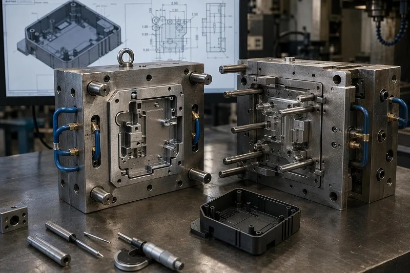
The vocabulary used throughout is worth fixing now. The cavity is the mold surface that forms the part’s outside; the core forms its inside. The line of draw is the direction the tool opens, and any feature not parallel to it needs side action, a lifter or a redesign. Shrinkage is the dimensional change between the cavity and the cooled part, and it is not a single number for a given resin. The cycle is the full sequence from mold close to part ejection, and its length is dominated by cooling — which is why wall thickness, not just strength, sets production cost.
Wall Thickness and Transitions in Injection Mold Parts
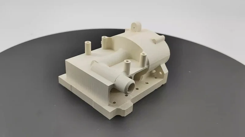
Wall thickness is the design variable with the widest reach. It determines how far melt can travel before it freezes, how long the part must cool, how much it shrinks and how unevenly, how much clamp force the tool needs, and whether sink marks appear on visible surfaces. Treat nominal thickness, heavy sections and transitions as one system: a part with a well-chosen nominal wall but an uncored heavy boss still has a thickness problem.
Choosing a Nominal Wall
Nominal wall is set at the intersection of three requirements: the structural load the part must carry, the flow length from gate to the farthest point, and the rheology of the chosen resin. A wall thick enough to fill but too thin for the load will deflect in service; a wall thick enough for the load but too thin to fill will short shot before the cavity is full.
The practical preference is a single uniform value across the part rather than a range. Uniform walls cool and shrink at similar rates, which keeps the part flat and dimensionally consistent. Where a range is unavoidable, keep the variation small and localize it away from cosmetic surfaces.
The chosen value propagates directly into cost. Thicker walls cool more slowly, so cycle time rises and clamp requirements grow with the projected area and cavity pressure. A part designed at the minimum thickness that satisfies structure and fill is usually the most economical version of itself.
Why Thick Sections Cause Sink and Voids
A heavy section holds more melt than its neighbors, so it stays molten longer. As it solidifies, it shrinks, and because the surrounding thinner walls have already frozen, the shrink has to come from somewhere: the surface pulls away from the mold wall and leaves a sink mark on the show face, or the interior pulls apart and forms a void. The mechanism is local mass plus late cooling, and it is why mass concentration — a thick boss, a solid corner, a heavy rib intersection — is the design decision to avoid rather than the sink mark itself.
Designing Gradual Transitions
Where thickness must change, step or taper it rather than jumping from thin to thick. A gradual transition spreads the shrinkage gradient between adjacent sections over a longer distance, which reduces the stress concentration at the junction and gives the melt a smoother flow path. Sharp steps do the opposite: they create a hot spot at the thick end and a flow restriction at the thin end.
Transition geometry also interacts with flow direction and gate location. A taper aligned with the flow fills more evenly than one that runs across it, and a transition placed near the gate sees hotter melt than the same transition at the end of fill. Decide transitions alongside gate position, not after.
Coring Heavy Sections
Coring removes material from heavy regions while preserving stiffness, converting a solid mass into a wall of controlled thickness. It is the primary remedy for sink and voids, and it shortens cycle time by reducing the mass that must cool.
The tooling consequence depends on orientation. Cores parallel to the line of draw are simple and economical. Cores at an angle to the draw usually require side action, lifters or loose cores loaded by hand, each of which adds cost and maintenance. Where a heavy section can be cored in the draw direction, do it; where it cannot, consider whether the geometry can be reoriented before accepting the side action.
Draft Angle Requirements for Injection Mold Parts
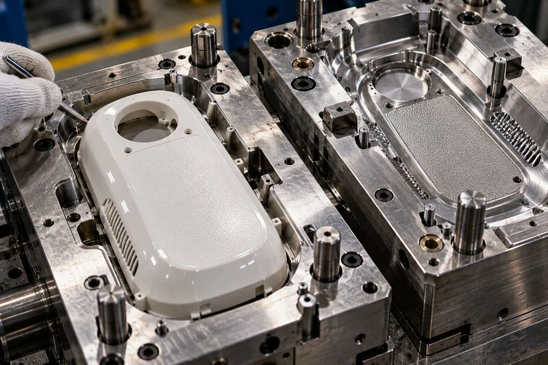
Draft is a moldability requirement, not a cosmetic allowance. It is the taper applied to walls parallel to the line of draw so the part releases cleanly, and omitting it is one of the most common reasons a design that looked finished fails at first shot.
Why Draft Is Required
As the part cools, it shrinks onto the core and grips it, while the outer surface presses against the cavity. Without taper, ejection has to overcome that grip by dragging the part along the mold surface, which scratches polished finishes, scuffs textured ones, and can bend or crack the part. In severe cases the part will not release at all, and forcing it damages the tool.
Prototypes can hide the problem. Additive and subtractive processes build the shape directly and have no ejection step, so an undrafted wall machines or prints without complaint. The deficiency only appears when the tool is cut, which is the most expensive moment to discover it.
How Much Draft Is Needed
There is no single angle for all designs. Wall thickness, resin, shrink rate, surface finish, feature depth and mold construction all shift the answer, and the practical rule is to apply as much draft as the geometry allows rather than the bare minimum. A common starting point is about 1° of draft per inch of cavity depth, adjusted for the factors above.
Depth-based guidance is more useful than a flat number. Shallow features can work with less draft; deep draws need more, because the contact area and the distance over which drag accumulates both grow with depth. Some molders accept draft as low as 0.25°–0.5° in favorable geometry and resin, but that is a case-by-case judgment, not a default.
Draft for Textured Surfaces
A textured cavity adds resistance to ejection, so textured walls need more draft than smooth ones. Texture depth and texture type both scale the additional allowance: light bead-blast textures call for roughly 3°, while medium and heavy textures generally need 5° or more. A common working figure is about 1.5° of extra draft per 0.001 in. (0.025 mm) of texture depth, and deep textures on deep draws compound the requirement.
Draft and Wall Parallelism
Inside and outside walls should be drafted in parallel so the mold avoids deep, narrow ribs between them. Deep ribs are hard to vent, hard to polish, hard to eject from and slow to manufacture. A core-cavity approach — designing the part so the core and cavity open up around the walls — keeps the tool accessible for finishing and generally makes molding easier. Where walls must converge, check that the resulting rib is wide enough to survive.
Ribs, Bosses and Snap Features in Injection Mold Parts

Ribs, bosses and snap features are where thickness control and draft converge. Each one reintroduces local mass or a local undercut, so each has to be reconciled with the wall and draft rules rather than designed in isolation.
Rib Design Rules
A rib adds stiffness without adding a thick wall, but its base is a local mass increase. As a rule, rib base thickness should be a fraction of the adjacent wall — commonly around half to two-thirds — so the rib does not create a sink mark on the opposite face. Where more stiffness is needed, multiple thinner ribs usually beat one thick rib: they distribute load and keep each base below the sink threshold.
Ribs need draft, typically at least 0.5° per side, and a base radius to avoid a sharp notch at the junction. Draft reduces the rib’s top thickness, so check that the tip still meets the minimum wall you need. Ribs should connect smoothly to side walls, bosses and mounting pads rather than ending abruptly.
Boss Design Rules
A boss is a local protrusion used for mounting or fastening. Its wall thickness should not exceed the main wall — a common guideline is no more than about 60% of the nominal wall — and its outside diameter is usually set at roughly twice the inside diameter of the hole, so the boss can carry the hoop stress a screw or insert imposes.
Hole dimensions must account for shrinkage: a hole molded to nominal will come out smaller after cooling, so specify the hole size with shrink in mind. Bosses should be located where structure is needed and connected to surrounding walls with ribs or gussets, which spreads load and reduces the chance of a sink mark on the face opposite.
Snap-Fit and Undercut Considerations
Snap features and undercuts introduce tooling complexity. An undercut that cannot release along the line of draw needs side action, a lifter or a hand-loaded core, each of which adds cost and maintenance. Where a redesign can eliminate the undercut, that is usually the best option.
For cantilever snap-fits, the flexing member needs adequate strain allowance for the resin, and the joint needs draft like any other feature. A common minimum thickness for the snap arm is about half the wall thickness. Design the snap so the tool can release it: the return angle, lead angle and undercut depth all determine whether the feature strips cleanly or requires side action.
Gate, Runner, Venting and Cooling Layout
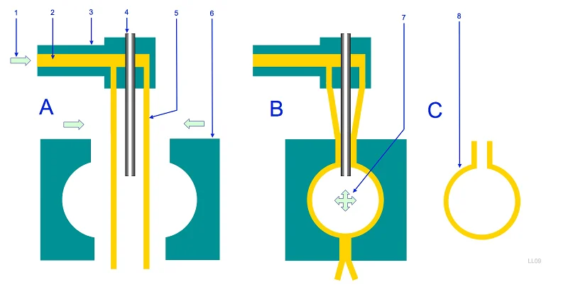
Part geometry decides what the part looks like; the feed and thermal system decides how it fills, where weld lines land, how much pressure is required and how uniformly it shrinks. Gate position, runner sizing, vent placement and cooling layout are design decisions, not afterthoughts.
Gate Location and Its Effect on Part Quality
Gate position sets flow direction, which in turn sets shrinkage orientation, fill pressure and the location of weld lines. A gate placed at one end of a long part pushes melt the full length, raising pressure and orienting shrinkage along the flow; a gate placed centrally shortens the flow but may put a weld line on a visible face.
Because gate location and wall thickness interact so strongly, decide them together. A gate chosen after the geometry is frozen often forces a compromise on thickness or finish that could have been avoided.
Runner and Venting Design
Runners deliver melt from the sprue to the gate at adequate pressure and temperature. Undersized runners raise pressure loss and shear; oversized runners add material that must be cooled and reground. Balance runner lengths across a multi-cavity tool so each cavity fills at the same rate.
Vents release the air displaced by incoming melt. Inadequate venting causes burning at the end of fill, weak weld lines, blisters, short shots, high melt and mold temperatures, slow fill rates and reduced process windows. Place vents at the last points to fill and at any feature that traps air — ribs, bosses, deep pockets — and size them so air escapes faster than the melt can seal them.
Cooling Channel Layout and Warpage
Cooling channels remove heat from the part, and their spacing, distance from the part surface and balance between cavity and core sides determine whether the part cools evenly. Uneven cooling creates temperature gradients, and temperature gradients translate into differential shrinkage: the hotter side shrinks more, and the part warps toward it.
Design cooling with consistent spacing and distance from the cavity surface, and balance the two mold halves. On challenging parts, separate controllers for each half may be needed to keep the temperature differential small — a common target is within about ±2 °C between halves to prevent directional warp.
Preventing Common Defects in Injection Mold Parts
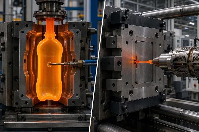
Most molding defects trace back to a design or process decision made earlier. Reading a symptom back to its cause tells you whether the fix belongs in the part model, the tool or the press.
Sink Marks and Short Shots
Sink marks originate in local mass and packing: a heavy section cools last, shrinks, and pulls the surface away from the mold. The design levers are coring, thinner ribs and bosses, and gradual transitions; the process lever is packing pressure and time.
Short shots originate in flow restriction, pressure loss or trapped air: the melt freezes before the cavity is full. The design levers are wall thickness, gate size and location, runner sizing and venting. The two defects are often confused because both leave an incomplete-looking part, but sink is a mass problem and short shot is a flow problem.
Warpage and Differential Shrinkage
Warpage is the visible result of unequal shrinkage across a part, appearing as twisting, bending or dimensional inaccuracy after ejection. The most common design cause is wall thickness variation: thick and thin sections cool at different rates and create shrinkage gradients. Cooling channel layout, fiber orientation in filled grades and packing pressure all contribute.
The design responses available before process adjustment are to balance wall thickness, improve cooling uniformity near thick areas, adjust gate location and rib placement to control flow direction, and consider post-mold annealing where residual stress is a concern. Process adjustment — balancing mold temperature, holding pressure and time — comes after the geometry has been corrected.
Weld Lines and Their Structural Effect
A weld line forms where two flow fronts meet and fuse: behind a hole or core pin, between multiple gates, or around an insert or boss. If the fronts have cooled skins when they meet, they do not fully blend, and the seam is often weaker than the surrounding material — especially in glass- and mineral-filled grades, where fibers do not cross the seam.
Weld lines cannot be eliminated from a part with a hole or multiple gates, but they can be moved and strengthened. Gate location determines where the seam lands; venting at the meeting point lets trapped air escape so the fronts press together; higher melt and mold temperature and faster fill keep the fronts hot. Place weld lines away from cosmetic surfaces and load-bearing areas, and test the seam where it carries load.
Drag, Scuffing and Ejector Marks
Insufficient draft and inadequate ejection produce surface damage. Drag and scuffing appear as scratches along the draw direction where the part rubbed the mold; ejector marks appear where pins pushed on the part.
Plan ejection so force is distributed: place ejector pins on hidden or non-cosmetic surfaces, size pads so they do not puncture or distort the part, and use stripper plates or rings where pins alone would mark the surface. Draft and polished tooling reduce the ejection force needed in the first place.
Setting Tolerances for Injection Mold Parts
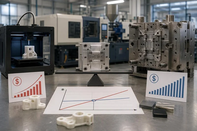
Tolerance is a negotiated outcome of shrinkage, geometry, tool capability and inspection method — not a number copied from a title block. Setting it well means understanding what each dimension must do and what the process can hold.
Shrinkage and Material Selection
Datasheet shrinkage values are references, not predictions. They are typically derived from a standard test bar — for example, a 5 in. × 1/2 in. × 1/8 in. bar edge-gated on the end — and a real part with different thickness, flow length and gate will shrink differently. Processing parameters such as melt temperature, mold temperature, fill time, hold time, hold pressure and cooling rate all shift the result.
Material class matters. Semi-crystalline resins can shrink roughly 1–3%, while amorphous resins typically shrink less than 0.7%, and filled grades shrink less and more anisotropically because fibers orient with flow. Material choice therefore constrains the tolerance band before the tool is designed.
Realistic Tolerance Bands
Tolerance feasibility scales with dimension length and feature type. Shrinkage grows with length, so a band that is easy on a small feature can be out of reach on a long one. Check the long dimensions first.
Critical functional dimensions — those that control fit, assembly, sealing or motion — warrant individual tolerances. Non-critical dimensions can rely on general tolerances. Discuss capability with the molder before the tool is cut: at a capability index of 1.00, a centered process fills the whole band and about 0.27% of parts fall outside it, so a band that looks generous on paper may still leave no room for normal variation.
Drawing and GD&T Practices
Datum-referenced geometric tolerancing communicates functional intent more precisely than tightened plus-or-minus values, because it states what a feature must do relative to the features it mates with. Designers, molders and inspectors then read the same requirement.
Plan critical dimensions steel-safe: leave extra steel or an insert so the tool can be adjusted after first sampling rather than welded or recut. Put that adjustment and resampling cost on the mold quote up front. Plastic parts also need their own tolerance framework — metal tolerance standards cannot simply be adopted for plastics, and standards such as ISO 20457:2018 address molded-part tolerances and acceptance conditions specifically.
From DFM Review to Production Validation
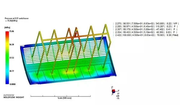
A design passes through a sequence of stages before it becomes a stable production part. Each stage confirms something different, and knowing what remains adjustable at each point prevents expensive surprises.
The DFM Review Stage
A design-for-manufacturability review examines the part model for wall thickness, draft, undercuts, gate and vent placement, ejection and tolerance feasibility. Findings that require a design change — an undrafted wall, a heavy boss, an undercut that forces side action — are cheapest to fix before the tool design is released. Findings that can be accommodated in tooling or process — a slightly thin wall, a gate position that can be adjusted — are noted and carried forward.
The review is most valuable early, when the part model is still fluid. A DFM review after the tool is cut can only confirm what is already committed.
Trial Shots and First Article Inspection
Trial shots reveal actual shrinkage, weld line position, ejection behavior and cooling performance — the things simulation predicts only approximately. Measure the trial parts in both directions and at various depths, and compare the measured shrinkage with the value used to cut the cavity.
First article inspection compares measured parts against the drawing and the qualification plan. It confirms whether critical dimensions are in tolerance, whether the process is stable, and whether any steel-safe adjustments are needed. If non-critical dimensions come out of spec but remain functional, revise the drawing to the new nominal rather than tightening the process.
Scaling to Stable Production
Before production, lock the process window, the inspection method, the acceptance conditions and change control. The qualified process — fill time, packing pressure, mold temperature, cooling time — should be documented and maintained across runs, and any change to resin, tool or process should trigger revalidation. Stable production is not a single good run; it is a process that holds its capability over many runs.
Choosing NOBLE to Support Your Injection Mold Parts Project

NOBLE is a China-based contract manufacturer with strong service and machining capability, supporting customers from prototype through volume production of injection mold parts and the tooling and fixtures around them. We are certified to ISO 9001:2015 and ISO 13485:2016, and our scope covers the full path from design to assembly — not molding alone.
That breadth matters for injection mold parts because the part is rarely the whole project. A design may need prototype iterations before the tool is cut, machined inserts or fixtures alongside the molded components, and assembly and inspection before shipment. NOBLE’s engineering and machining resources let those steps run under one roof, so a design change found at trial shot can be addressed in the part model, the tool and the surrounding hardware together rather than across separate suppliers.
If you are planning an injection mold parts project, send us the part model and the functional requirements. We will review the design for manufacturability and quote the path from prototype to production.
FAQs About Injection Mold Parts
How much draft should injection mold parts have?
There is no single angle. A common starting point is about 1° per inch of cavity depth, with more for deep draws, textured surfaces and certain resins. Textured walls need roughly 3° for light textures and 5° or more for medium and heavy textures. Apply as much draft as the geometry allows.
What wall thickness should I use?
Use the minimum uniform wall that satisfies structural load and flow length for your resin. A single uniform value cools and shrinks more evenly than a range. Thicker walls raise cycle time and clamp requirements, so avoid mass concentration.
How thick should ribs and bosses be?
Rib bases are commonly around half to two-thirds of the adjacent wall, and multiple thinner ribs usually beat one thick rib. Boss wall thickness is often kept to about 60% of the nominal wall, with outside diameter roughly twice the hole diameter.
How does gate location affect part quality?
Gate position sets flow direction, fill pressure, shrinkage orientation and weld line location. Decide it alongside wall thickness, not after the geometry is frozen.
Why do my parts warp?
Warpage comes from unequal shrinkage, most often caused by wall thickness variation or unbalanced cooling. Balance walls, improve cooling uniformity and adjust gate location before tuning the process.
Are weld lines a structural problem?
Often, yes. Weld lines form where flow fronts meet and are weaker than the surrounding material, especially in filled grades. Move them away from load-bearing and cosmetic surfaces, and test the seam where it carries load.
How realistic are my tolerances?
Tolerance feasibility depends on dimension length, feature type, resin and tool capability. Datasheet shrinkage is a reference, not a prediction. Discuss capability with the molder before the tool is cut, and leave critical dimensions steel-safe.
What is the validation sequence?
DFM review, tool construction, trial shots, first article inspection and production qualification. Each stage confirms something different, and the earlier stages are where design changes are cheapest.