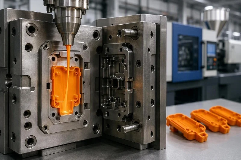
Özel plastik enjeksiyon kalıplama is the design and manufacture of a mold built around one specific part geometry, then the injection of molten thermoplastic into that cavity to produce repeatable parts. The word “custom” is the whole distinction: a catalog or stock molding operation reuses an existing tool for a part that already exists, while a custom program starts with your CAD model and ends with a tool that exists for no other product.
That distinction has a commercial consequence you feel for the life of the program. The mold is a fixed upfront investment tied to a single design, so every decision made before steel is cut — wall structure, draft, gate location, resin grade, cavity count — sets your unit cost, your achievable tolerance, your lead time, and how expensive it will be to revise the part six months after launch.
If you are a product developer or a buyer holding a CAD model and a launch date, this guide is organized around the decisions you actually have to make: what custom molding commits you to, how tooling shapes the economics, which design rules most often force a tool rework, how resin and shrinkage limit the tolerances you can specify, what to send in an RFQ, what quality certification does and does not tell you, and how the prototype-to-production path should be gated. It draws on published engineering references, polymer technical literature and standards documentation, and NOBLE’s own service scope is described in a dedicated section.
Hangi Özel Plastik Enjeksiyon Kalıplama Aslında şu anlama geliyor:

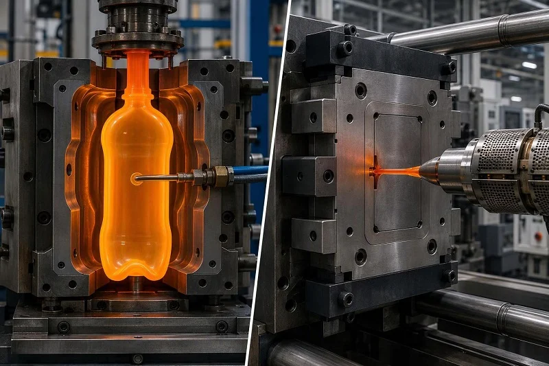
Custom plastic injection molding itself is a cycle: melt the resin, inject it under pressure into the cavity, pack and hold to compensate for shrinkage as the polymer solidifies, cool the part to dimensional stability, then open the mold and eject. What makes a project görenek is the mold. A purpose-built tool is designed and machined for your geometry alone; standard molding reuses a tool that already exists for a catalog part, which is why stock molding carries no tooling charge and no design freedom.
Within a custom program, the attributes open to specification include:
- Part geometry and wall structure — the shape, wall thickness, ribs, bosses and radii that define the part.
- Resin grade and color — the specific polymer, grade, colorant and any additive package.
- Insert and overmold features — metal inserts placed in the cavity before injection, or a second resin shot bonded over a substrate.
- Yüzey — set by the mold surface and classified under the SPI standards.
- Gate and ejector placement — where the melt enters and where the part is pushed out, both of which leave marks.
- Cavitation count — how many parts the tool produces per cycle.
“Custom” does not mean unlimited freedom. Custom plastic injection molding still imposes its own physics: vertical faces need draft to release, wall thickness should stay as uniform as the design allows, and every dimension in the cavity has to be cut oversize to allow for shrinkage. A design that ignores these constraints is still manufacturable in principle, but the tool becomes more expensive and the part more likely to be reworked.
The economic consequence follows directly. Tooling cost is fixed and independent of the number of parts you run, so custom molding rewards designs that will not change. A design revision after the tool is cut means welding, re-machining or replacing cavity details — work that buys you no additional parts.
Why Custom Plastic Enjeksiyon Kalıplama Takımları Changes the Economics of a Part
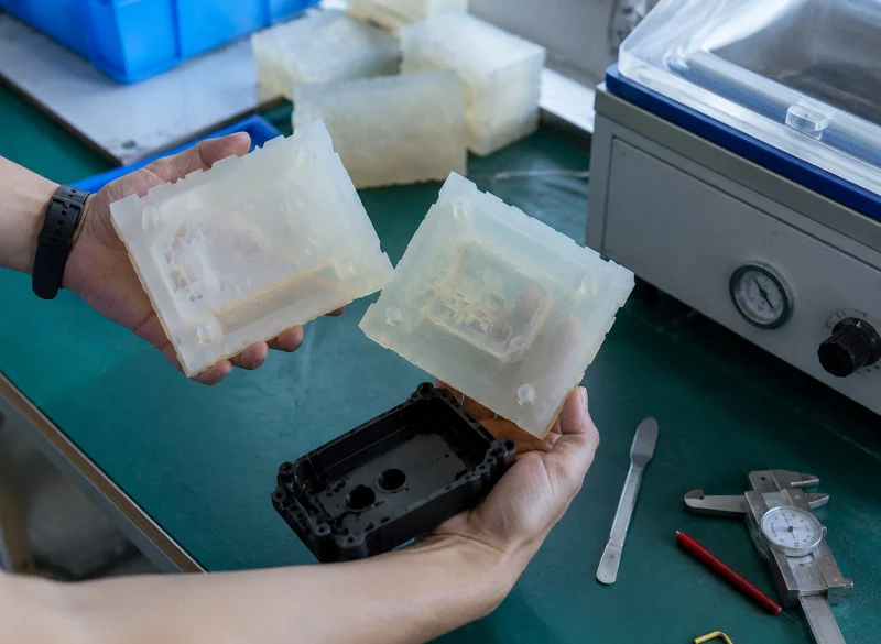
Three costs drive an custom plastic injection molding quote: tooling, material and machine time. Tooling is determined by the total cost of designing and machining the mold. Material cost is driven by the volume of resin used and its price per kilogram. Production cost is driven by the total time the machine is occupied.
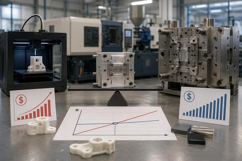
The structure matters because only one of the three is fixed. Published engineering guidance puts tooling costs as constant — starting at roughly $3,000 to $5,000 — and independent of the total number of parts manufactured, while material and production costs scale with volume. That is why the same part can quote at a painful unit price for 300 pieces and a comfortable one for 300,000: the tooling is spread across a very different denominator.
The same reference suggests about 500 units as the point where economies of scale begin to offset the relatively high initial tooling cost, and gives a typical cycle time of 15 to 60 seconds depending on part size and mold complexity. Compare that with CNC'de işleme or 3D printing, which may need minutes to hours for the same geometry, and the volume logic becomes obvious.
The trade-off you accept is time. Custom molding carries longer lead times than the alternative processes because the tool has to be built first — the reference gives a typical turnaround of 6 to 10 weeks, of which 4 to 6 weeks is mold manufacture and 2 to 4 weeks is production and shipping. Design changes extend that. A desktop 3D printer can deliver overnight; industrial 3D printing typically runs 3 to 5 days; CNC machined parts are commonly delivered within about 10 days.
The practical conclusion is a fork in the road. At low volume, favor a simple tool, a low cavity count, or a prototyping route that avoids committing to production tooling at all. At high volume, the fixed tooling cost is amortized into irrelevance, and hardened tool steel with higher cavitation becomes the cheaper choice per part — provided the design is genuinely frozen.
Design Rules That Decide Whether a Custom Part Molds Well
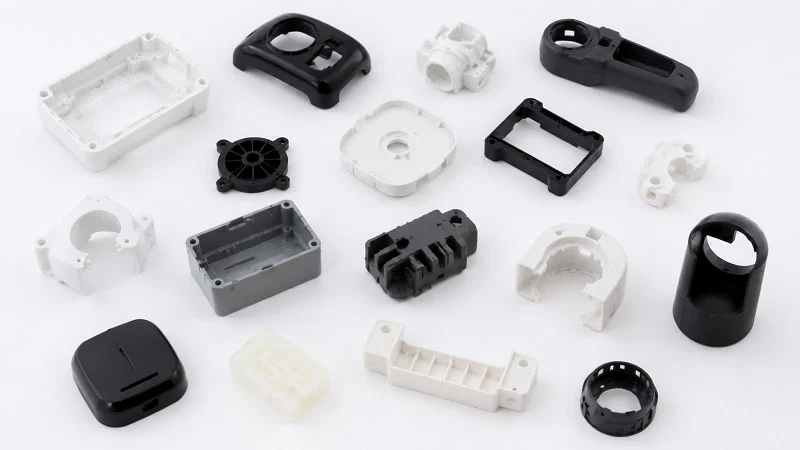
Most tool reworks trace back to a small set of design decisions. Checking them against your CAD model before you send it out is cheaper than checking them after T1.
Duvar kalınlığı
Keep the nominal wall as thin and as uniform as the part allows. Thick sections stay molten longer than the surrounding material, which produces sink, warpage and internal stress, and they lengthen the cooling portion of every cycle. Where sections of different thickness cannot be avoided, transition between them with a chamfer or fillet rather than a step. Where you need stiffness, ribs and gussets add it without adding bulk — a 10% increase in wall thickness buys roughly 30% more stiffness, but at the cost of cycle time and defect risk. Bosses deserve particular care: a solid boss with walls as thick as the main wall is a classic sink-mark generator, while a cored boss with gussets cools evenly and holds a screw without cracking.
Taslak - Draft
Every vertical face that runs parallel to the direction of mold opening needs draft, or the part will drag and scrape on ejection. One degree is the usual baseline for smooth, untextured surfaces. Textured surfaces need more — commonly 3° to 5°, depending on the depth and pattern of the texture — because the texture itself resists release.
yarıçaplar
Round internal and external edges wherever the design permits. Sharp corners concentrate stress and impede melt flow; generous fillets at the base of ribs, bosses and snap-fits are standard practice.
Undercut'lar
Any feature that cannot be released in the straight pull direction requires moving mold components — slides, lifters or cams. These are a documented cost driver: one design reference puts side-action cores and similar in-mold mechanisms at 15% to 30% added tooling cost, or roughly $1,000 to $1,500 minimum. Avoid them unless the function genuinely requires the feature, and consider whether the undercut can be stripped, placed on the parting line, or eliminated by a small geometry change.
These are principles, not a substitute for a tool design. A DFM review is where each rule gets checked against the specific parting line, gate position, ejection layout and steel plan for your part — and where a designer can tell you which of your features will cost you money.
Material Choice and Shrinkage: Why Tolerances Are Not Free
The mold cavity is cut larger than the finished part, because the resin contracts as it cools. How much it contracts depends first on the polymer family.
Amorphous Thermoplastics
ABS, polycarbonate, polystyrene, PPO — cool from a disordered molecular structure and shrink comparatively little, across a narrow range. Published comparative values put ABS at 0.004–0.009 in./in., polycarbonate at 0.005–0.007, and polystyrene at 0.004–0.007.
Semi-Crystalline Thermoplastics
Polypropylene, polyethylene, nylon, acetal — do something extra. As they cool, crystals form, and the crystalline regions shrink more than the amorphous ones and at different rates. That imbalance adds contraction on top of ordinary thermal cooling and makes the result sensitive to machining conditions. The same reference gives polypropylene 0.010–0.025 in./in., polyethylene 0.015–0.040, nylon 6-6 0.007–0.018, and acetal 0.018–0.025 — wider ranges, sitting higher.
That spread is why tolerances are not free. A semi-crystalline resin does not have a single shrinkage value you can dial into the tool; it has a range, and where in that range your part lands depends on melt temperature, cooling rate, part thickness and gate dimensions. Covestro’s technical treatment of shrinkage makes the same point from the other direction: thicker walls cool more slowly, reach a higher degree of crystallization, and therefore shrink more, so a part with mixed wall thicknesses can shrink differently in different regions and warp as a result.
The source’s own caution is worth repeating plainly: shrinkage data obtained under controlled laboratory conditions and simple mold geometries should be used only for comparison and should not be applied directly to actual tool design. The number in a data sheet is a starting point for a mold flow analysis, not a dimension you can trust blind.
The design consequence is that you should specify tolerance from what the application actually needs — the fit, the sealing surface, the assembly interface — rather than copying a generic table. If a dimension does not matter functionally, loosening it costs you nothing and may save the toolmaker real effort. If it does matter, say so explicitly and expect the tool design and process window to be built around it.
Prototype, Pilot Run and Volume Production: Choosing the Right Stage
There is a three-stage path from CAD model to volume parts, and each stage exists to keep you from spending the next stage’s money too early.
Stage One: Prototype Before Committing To Tooling
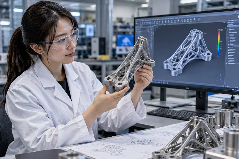
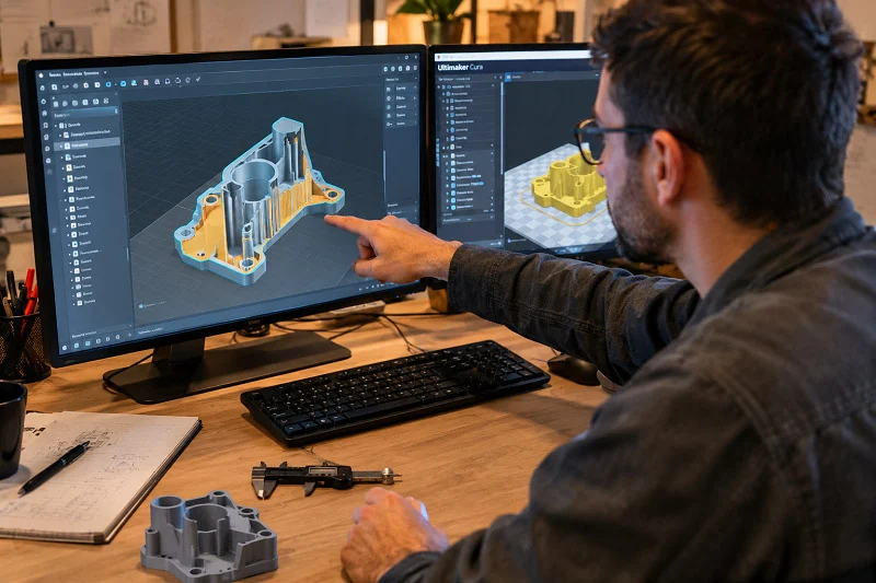
Test form and function while change is still cheap. The engineering reference lists three routes: 3D printing (SLS, SLA or material jetting), CNC machining in plastic, and low-run custom plastic injection molding using 3D-printed molds. Each trades realism against cost and speed. 3D printing is the cheapest and fastest, and designs optimized for molding print easily, but not every molding resin is available and printed parts are typically weaker. CNC machining gives material properties identical to the molded part with excellent accuracy, at higher cost and longer lead time. Low-run molding simulates the actual process and mold design most faithfully, and is the most expensive of the three.
Stage Two: Pilot Run
Aluminum molds are relatively easy to manufacture and lower in cost — the reference gives about $3,000 to $5,000 — and withstand roughly 5,000 to 10,000 injection cycles. Typical cost per part at this stage runs $1 to $5 depending on geometry and material, with a lead time of 6 to 8 weeks. Critically, the reference states that parts from pilot aluminum molds have physical properties and accuracy identical to parts from full-scale tool steel molds. This is the stage where you validate the design in the real process, run fit and function testing on real resin, and lock the drawing.
Üçüncü Aşama: Hacim Üretimi
For 10,000 to 100,000+ units, molds are CNC machined from tool steel and can withstand very high cycle counts — the reference cites 100,000+ cycles for full-scale production tools.
One terminology trap is worth flagging. “Pilot run” does not mean “not real production.” If your program only needs a few thousand parts, the aluminum pilot tool is your final production step, and you should plan and approve it as such rather than treating it as a temporary stage.
Each stage should end with an approval gate: prototype sign-off on form and function, pilot sign-off on dimensional report and cosmetic acceptance, and only then a commitment to production tooling. Skipping a gate is how programs end up welding a steel tool because a fit problem surfaced after the mold was cut.
Tolerances, Surface Finish and Inspection Expectations
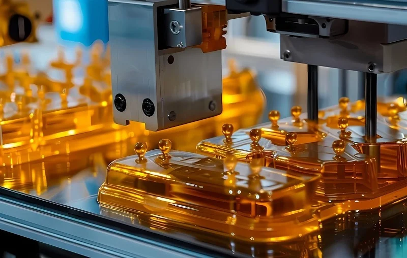
Custom plastic injection molding typically produces parts with tolerances of ±0.500 mm (0.020 in.). Tighter tolerances are feasible in certain circumstances — down to ±0.125 mm (0.005 in.), and in exceptional cases tighter still — but they increase cost drastically. The reference also notes a practical workaround for small production runs under 10,000 units: a secondary operation such as drilling can improve accuracy on specific features, which is often cheaper than building the precision into the tool.
Surface finish is set by the mold surface, not by the resin. Cavity surfaces can be polished to a very high degree to produce mirror-like parts, or bead blasted to create a texture, and the SPI standards define the levels that can be achieved. Two consequences follow. First, cosmetic requirements must be documented before the tool is cut, because polishing or texturing is applied to the steel. Second, gate and ejector locations leave visible marks — a gate vestige, an ejector witness — so the cosmetic zones of your part need to be mapped against where the tool will physically have to gate and eject. A cosmetic surface that sits directly over an ejector pin is a design conflict, not a production surprise.
The defects you are most likely to encounter each have a design or process cause you can act on:
- Lavabo — a surface depression over a thick section or a poorly designed rib or boss. Cause: thick walls and slow local cooling.
- Sürükleme izleri — scraping on ejection as the shrinking part grips the mold. Cause: vertical walls with insufficient draft.
- Örgü hatları — hairline discoloration and a weak seam where two melt fronts meet. Cause: abrupt geometry changes or holes that split the flow.
- Kısa çekimler — an incomplete part where trapped air or thin walls prevented the cavity from filling.
Inspection criteria belong in the purchase specification, agreed before the tool is built, not in a conversation after the first shipment. Define which dimensions are critical, which surfaces are cosmetic, what defect criteria apply, and what report you expect with each lot.
What to Put in an RFQ for an Accurate Quote and Timeline
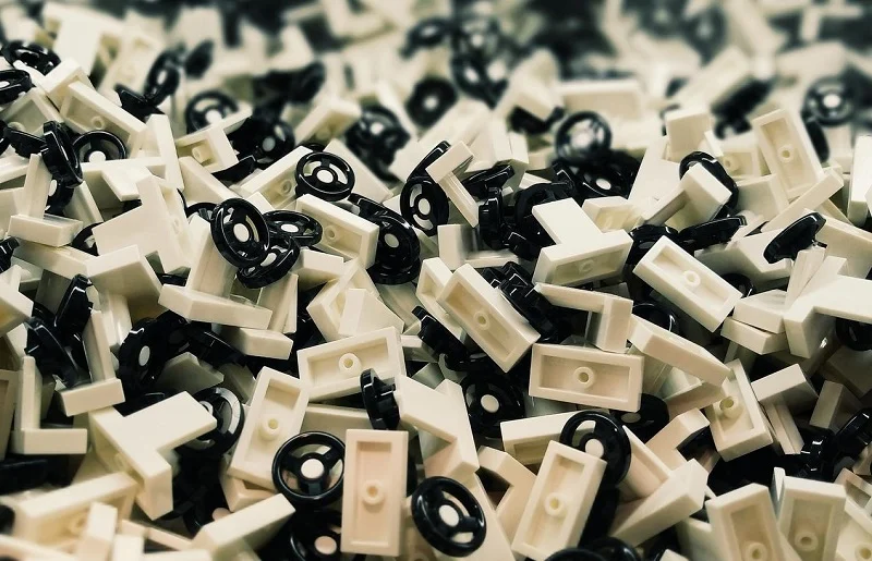
An incomplete RFQ produces a quote that has to be revised, which costs you calendar time you probably do not have. The submission package below is what a molder needs to quote firmly and comparably.
- 3D CAD modeli in a neutral format. STEP is the most broadly useful starting point; Parasolid, IGES or a native format may be acceptable depending on the engineering team’s software.
- 2B çizim with tolerances, datums and critical dimensions marked. The model tells the supplier what the part looks like; the drawing tells them what failure means.
- Resin specification — the exact grade, not just the polymer family. Grades within the same family differ in shrinkage, viscosity, impact strength, heat performance, flame rating, UV stability, glass-fiber content and regulatory documentation, and those differences change mold design, steel selection, venting, gating and unit cost.
- Hacimler — expected annual demand plus the first order quantity and any growth scenario. Volume determines cavitation and tool steel selection, which are two of the largest line items in the quote.
- Cosmetic and surface finish requirements — the SPI finish, the cosmetic zones, the color standard, and the defect criteria. “Perfect” is not an inspection specification.
- Insert, overmold or assembly requirements, including any secondary operations such as machining, painting, pad printing, ultrasonic welding or final assembly.
- Regulatory or documentation needs — first-article inspection reports, material certificates, PPAP-style packages, or traceability records, depending on your industry.
- Zamanlama — target launch date and the milestones you need: DFM, T1 sample, approval, production.
Two items belong in the quoted scope rather than in a later conversation. First, a DFM incelemesi before steel is cut, with the supplier classifying critical dimensions and flagging risk areas. Second, a trial-shot plan — what will be sampled at T1, how it will be inspected, and what the correction loop looks like. Ask explicitly what happens to the tool if the design changes after it is cut, and who owns the tool. Tool ownership, transfer terms and change-control obligations should be in writing before the purchase order, not negotiated during a dispute.
How NOBLE Supports Custom Plastic Injection Molding Programs
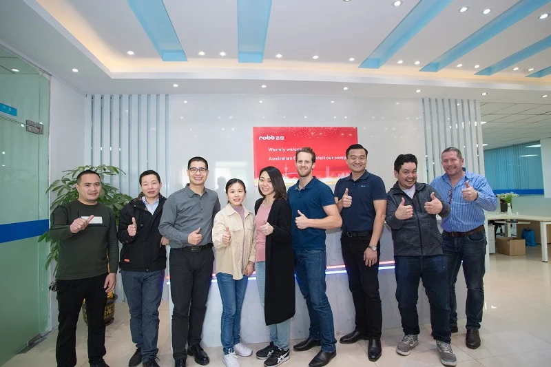
NOBLE is a China-based contract manufacturer that works inside exactly this workflow. We are a Sino-British joint venture, recognized by the government as a “National High-tech Enterprise,” with more than ten years of experience providing one-stop custom manufacturing from prototyping through production.
For a custom plastic injection molding program, that means the scope covers the full chain rather than molding alone: design support, prototyping, tooling and molding, machining, finishing and assembly. A program does not have to be split across several vendors, with the tolerance drift and handoff risk that splitting introduces. When your part later needs inserts, secondary machining, polishing, painting, pad printing, ultrasonic welding or final assembly, those operations sit within the same manufacturing relationship.
How ISO 9001:2015 and ISO 13485:2016 Certification Should Be Read
NOBLE holds both ISO Kalite Yönetim Sistemi hem de ISO Kalite Yönetim Sistemi certification, so the questions below are ones we can answer directly for a custom plastic injection molding program. The two certificates answer different questions, and it helps to know which is which before you weigh them in a sourcing decision.
ISO Kalite Yönetim Sistemi is the general quality management system standard. It addresses custom plastic injection molding control, document control, corrective and preventive action, management review and continual improvement. It tells you that the supplier operates a documented, audited system for controlling how work is done and how problems are corrected — across all of its manufacturing, not just molding.
ISO Kalite Yönetim Sistemi is the medical-device-specific quality management system standard. It adds requirements around risk management, traceability, validation and regulatory documentation that general manufacturing standards do not impose. Its weight has increased for U.S. device programs: the FDA’s Quality Management System Regulation, effective February 2, 2026, amended the device current good manufacturing practice requirements of 21 CFR Part 820 and incorporated ISO 13485:2016 by reference. In other words, the international standard is now part of the U.S. regulatory framework for device quality systems, which is why a supplier holding it is materially easier to qualify for medical work.
Now the limit, stated plainly: certification confirms that a documented quality management system is in place and has been audited. It does not confirm that your specific part will meet your specific tolerance. Those are different claims, and conflating them is how buyers get surprised.
What to verify yourself, regardless of certificates:
- The certificate’s scope and issuing body — which sites and which activities are actually covered.
- The inspection report for your part — the actual dimensional results on the actual parts, not a statement of capability.
- İlk makale onayı — a documented sign-off on the first parts produced from the production tool, against the drawing you released.
- The change-control process — what happens, and who approves it, if the resin supplier, tool, machine, cavity configuration or process window changes during the program.
A supplier that welcomes those questions is usually the one whose system will hold up under them — and with both certificates in hand, NOBLE can answer them against your specific part rather than in general terms.
If you have a CAD model and a launch date, the most useful first step is to send the RFQ package described in the previous section. We will identify any remaining questions before confirming the quotation scope, so that a custom plastic injection molding program starts from a quoted scope everyone agrees on.
FAQs about Custom Plastic Injection Molding
What does “custom” change in custom plastic injection molding versus standard molding?
Standard molding reuses an existing tool for a catalog part, so there is no tooling charge and no design freedom. Custom plastic injection molding builds a purpose-made mold for your geometry, which means you can specify part geometry and wall structure, resin grade and color, insert and overmold features, SPI surface finish, gate and ejector placement, and cavity count. The cost of that freedom is a fixed tooling investment tied to one design.
How do I choose between prototype molding, low-volume and high-volume production?
Match the tool to the volume and to how frozen the design is. Below roughly 500 units, tooling rarely repays itself — use 3D printing or CNC machining. From about 500 to 10,000 parts, an aluminum pilot tool (roughly $3,000–$5,000, good for 5,000–10,000 cycles) produces parts with properties and accuracy comparable to steel-tool parts, and may be your final production step. Above 10,000 parts and into the 100,000+ range, CNC-machined tool steel with higher cavitation is the economic choice. The deciding question is not only volume but design maturity: if the design may still move, a soft tool is cheaper to change.
Which design features drive tooling cost and delay?
Undercuts are the biggest single driver, because they require slides, lifters or cams — documented at 15% to 30% added tooling cost, or roughly $1,000 to $1,500 minimum. Beyond that: thick or highly non-uniform walls (longer cooling, sink and warp risk), insufficient draft on textured faces (drag marks and rework), sharp corners, and cosmetic requirements that conflict with gate and ejector placement. Each of these is cheaper to fix in CAD than in steel.
How do material and shrinkage limit the tolerances I can realistically specify?
Amorphous resins such as ABS, polycarbonate and polystyrene shrink little and across a narrow range (roughly 0.004–0.009 in./in.). Semi-crystalline resins such as polypropylene, polyethylene, nylon and acetal shrink more and across a wider range, because crystallization adds contraction on top of thermal cooling. Within that range, melt temperature, cooling rate, wall thickness and gate dimensions all shift the result. Published shrinkage values are for comparison and should not be applied directly to tool design. Specify tolerance from the application’s real requirement, and expect the tool to be built around a mold flow analysis rather than a data sheet number.
Teklif talebine (RFQ) neler eklemeliyim?
A neutral-format 3D model (STEP is a good default), a revision-controlled 2D drawing with tolerances and critical dimensions, the exact resin grade with color and additive requirements, annual and first-order volumes, cosmetic and surface finish requirements, insert or assembly requirements, any regulatory or documentation needs, and your target milestones. Ask for the DFM review and trial-shot plan to be included in the quoted scope, and settle tool ownership and change-control terms in writing before the order.
What do ISO 9001:2015 and ISO 13485:2016 actually certify?
They certify that a documented quality management system is in place and audited — ISO 9001:2015 for general manufacturing quality management, ISO 13485:2016 for medical-device-specific requirements including risk, traceability and regulatory documentation. Since February 2, 2026, the FDA’s QMSR incorporates ISO 13485:2016 by reference into 21 CFR Part 820, which is why the medical certificate carries weight for U.S. device programs. Neither certificate guarantees that your specific part will meet your specific tolerance. Verify the certificate’s scope and issuing body, review the inspection report for your parts, and require first-article approval.
What does the realistic prototype-to-production path look like?
Three stages, each ending in an approval gate. First, prototype with 3D printing, CNC-machined plastic or low-run molding to prove form and function while change is cheap. Second, pilot run in an aluminum tool to validate the design in the custom plastic injection molding process and lock the drawing. Third, volume production in tool steel once the design is frozen. Expect 6 to 10 weeks for a typical custom molding turnaround, of which 4 to 6 weeks is mold manufacture — and plan for design changes to extend it.