Introduction
A shaft does three jobs. It supports rotating parts. It transmits power. It keeps everything spinning true. That is the basic function. Fail at any one, and the whole system stops. Bad shaft design has consequences.
Here is the purpose of this article. Catch problems before metal gets cut. That is an efficient mechanical shaft design. And when it is time to make the part, CNC machining of shafts demands its own set of rules. This guide covers both.
Category 1: Stress Concentration & Fatigue Strength in Mechanical Shaft Design
The shaft will continuously rotate, stop, rotate again, and stop. Each cycle increases the stress. Eventually, it will break. Our core objective is simple: to improve fatigue life and prevent premature failure.
Smooth the transitions
An abrupt change in diameter is a crack waiting to happen. The stress piles up right at the corner. The fix is boring but essential. Use proper fillet radii. Keep the corner round, not sharp. This is not cosmetic. It is structural.
Relieve the press-fit zones
An interference fit locks a bearing or a gear onto the shaft. The fit itself creates stress. The edge of the fit zone is where things get bad. Add a relief groove at the end of the fit. Or lower the stiffness at the fit ends. The stress backs off. The shaft lasts longer.
Fix the keyway
Keyways are necessary. They are also stress concentrators. The sharp inside corner of a keyway is a fracture origin. Use end radii on the keyway floor. Break every sharp edge. A small radius costs nothing in machining time. It pays back in reliability.
Make the surface stronger
Fatigue cracks start at the surface. A rough surface has microscopic notches. A smooth surface does not. Roller burnishing compresses the surface layer. Polishing removes the machining marks. Shot peening adds compressive stress. All three methods boost fatigue strength significantly. Good shaft design accounts for surface finish as a structural variable, not just an aesthetic one.
In mechanical shaft design, the details matter. A fillet here. A groove there. A polished surface. These are not extra steps. They are what separates a shaft that runs for years from one that snaps in the field. And during CNC machining of shafts, these features must be programmed from the start. Adding a radius after the fact is too late. The toolpath either includes it or does not. Plan it early.
Category 2: Assembly & Manufacturing Feasibility in Mechanical Shaft Design
A shaft that breaks is bad. A shaft that cannot be assembled is worse. The core goal here is simple: make it machinable, make it assemblable, make it serviceable. And stop damaging parts during installation.
Help the interference fit go together
Pressing a bearing onto a shaft is not a joke. Too much force, and something gets damaged. Add a lead-in taper at the start of the fit zone. The taper guides the part on. It centers everything. Also, pick the right interference level. Not every fit needs to be a hammer fit. Some just need to be snug.
Stop the edges from digging in
Sharp starting edges are trouble. They go to the mating part. They scratch the surface. Use chamfers. And make sure the mating surfaces do not start at the exact same spot. Offset the starting positions. One feature engages first, then the next. No binding. No galling.
Let the air out
Blind holes trap air. Push an interference-fit shaft into a blind hole, and the air has nowhere to go. The pressure builds. The shaft stops halfway. The fix is simple. Add a vent hole through the bottom. Or cut axial grooves along the shaft. The air escapes. The shaft seats fully.
Spread the keyways around
Multiple keyways on the same cross-section weaken the shaft. A lot. Three keyways stacked together leave almost no material in between. The solution? Space them evenly. One hundred twenty degrees for three keyways. One hundred eighty degrees for two. The load spreads. The shaft stays strong.
Make the keyway cuttable
A keyway is a CNC machining operation. Some keyways are easy. Some are nightmares. Prefer disc cutters over end mills. Disc cutters produce a clean, radiused root. End mills leave a sharp corner. That sharp root notch is a crack starting point. Avoid it. Good shaft design anticipates the cutter before the programmer gets the job.
Avoid long, slender, deep holes
Drilling a deep, thin hole is slow. The drill wanders. The hole comes out crooked. Consider an off-axis hole instead. Or break the long hole into shorter, segmented holes. The part gets easier to make. The cost goes down.
Give the lock washer a place to sit
A lock washer needs something to lock against. A tab slot. A locating shoulder. Without these, the washer just spins. It does nothing.
Do not load the retaining ring
Elastic retaining rings are for positioning. They hold a component in place axially. They are not for carrying heavy loads. Do not use a retaining ring as a force closure. It will fail. The ring pops out. The part moves.
During CNC machining of shafts, these features are either in the model or they are not. Adding a chamfer after programming starts is a change order. Adding a vent hole after the shaft is made is a redesign. Get them into the mechanical shaft design early. The machinist will thank you. The assembly tech will thank you.
The customer will never know—which is exactly the point.
Category 3: Load & Deformation Optimization in Mechanical Shaft Design
A shaft bends under load. Too much bend, and seals leak. Bearings wear out. Gears misalign. The core goal is straightforward: lower the peak stresses, cut down the deformation, and make the whole thing stiffer.
Put bearings close to the load
This is basic, but people get it wrong. The load goes in the middle. The bearings go near it. Not at the far ends. A long overhang is a lever. The lever multiplies the bending moment. Keep the overhang short. The shaft stays straight.
Share the load
One gear takes all the torque? That gear tooth bends. The shaft twists. Use two smaller gears instead. Or add multiple parallel load paths. The load splits. Each path carries less. The stiffness goes up. The stress goes down.
Drive from the center
Here is a common problem. Power comes in at one end. It travels to the other end. The near end twists. The far end lags. The angular difference causes binding. Drive from the center instead. The torque splits evenly. Both ends see the same twist. No differential deformation.
Keep hollow shafts thick under the keyway
A hollow shaft is light. A hollow shaft with a keyway is weak at that spot. The wall collapses inward. The keyway splits open. Make the wall thick enough under the keyway. Or use a shallower keyway. Or fill the hollow section with a solid plug at the keyway location. Do not ignore this. A collapsed shaft stops a production line.
Define the fit zones clearly
Press-fit. Transition-fit. Clearance-fit. They are not the same. Do not blend them. A press-fit zone needs a different diameter than a clearance-fit zone. Specify the dimensions. Call out the tolerances. The machinist needs to know which part of the shaft gets pressed and which part gets greased.
Avoid zero reaction support
A bearing with no load is a bearing that rattles. The shaft vibrates. The bearing skids. The cage fails. Always ensure every support point carries some reaction force. Even a small preload is better than zero. A constrained shaft is a happy shaft.
In mechanical shaft design, these choices drive the final shape. Bearing placement determines the length. Load sharing determines the diameter. The center drive determines the symmetry. And during CNC machining of shafts, these features become toolpaths. A short overhang means less material to remove. A thick wall under a keyway means a different cutter pass. Good shaft design considers both the physics and the machining. They are the same problem, looked at from two sides.
Category 4: Positioning & Connection Design in Mechanical Shaft Design
If you see shaft displacement, that’s a sign of damage to the shaft. This will cause the bearings to lose their preload, the gears to come out of mesh, and the whole thing to eventually disintegrate due to vibration. The main goals are to make sure it’s well-positioned and connected securely, and to stop components from loosening because of vibrations.
Use shoulders first, rings second
A shaft shoulder is a step in the diameter. The mating part butts against it. That is solid. That is reliable. A retaining ring or a screw is weaker. The ring can pop out. The screw can back off. Prioritize shoulders or collars for positioning. Use retaining rings only when a shoulder is impossible.
Lock the threads
A rotating shaft spins its nuts loose. It is not a question of if, but when. Fine threads hold better than coarse threads. A lock washer adds friction. Double nuts jam against each other. Use at least one of these methods. Better yet, use two. A loose nut on a rotating shaft is a projectile waiting to happen.
Leave room for heat
Shafts, bearings, and housings get hot. Not at the same rate. Not by the same amount. A shaft expands more than a cast iron housing. A steel bearing expands differently than an aluminum housing. Account for thermal expansion in the clearances. A design that fits perfectly at room temperature may seize at operating temperature. Or it may rattle. Neither is acceptable.
Do not stub a small shaft into a big one
A small-diameter shaft bolted directly to the end of a large-diameter shaft creates a stiffness jump. The small shaft bends. The large shaft does not. The connection point sees a massive bending moment. Cracks start at the joint. Use a flange instead. Or a flexible coupling. The stiffness transitions gradually. The bending moment spreads out. The assembly lasts.
In mechanical shaft design, positioning is not an afterthought. It is the difference between a shaft that runs for years and one that needs service every month. A shoulder is cheap. A retaining ring is cheap. A loose nut is expensive. During CNC machining of shafts, these features add machining time. A shoulder requires a turning pass. A groove for a retaining ring requires a separate tool. That time is worth it. Good shaft design pays for itself in reduced field failures. A part that stays put never needs a warranty. That is the goal.
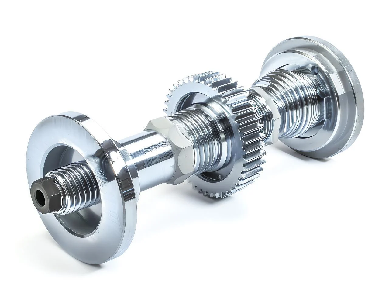
Category 5: Special Operating Conditions & Dynamic Behavior in Mechanical Shaft Design
A shaft that runs fine at low speed can tear itself apart at high speed. The core goal is simple. Avoid resonance. Keep things stable at speed. Manage the critical speeds before they manage you.
Stay away from the natural frequency
Every shaft has a natural frequency. It is the speed at which the shaft wants to vibrate. Run the shaft at that speed, and the vibration grows. It feeds on itself. The amplitude jumps. The shaft hits the housing. Things break. Keep the operating speed away from that natural frequency. Calculate the critical speeds early. Change the diameter. Change the bearing span. Shift the frequency. Do not guess.
Put the coupling close to the bearing
A high-speed shaft with a coupling hanging off the end is a problem. The overhang acts like a lever. Any imbalance in the coupling gets magnified. The shaft whips. Position the flexible coupling as close as possible to the bearing. The overhang length gets shorter. The unbalanced response gets small. The shaft stays smooth.
Add damping and balance the assembly
A high-speed shaft needs two things. First, balance. The mass distribution around the centerline must be even. A heavy spot creates a once-per-revolution force. That force excites vibration. Spin the assembly on a balancing machine. Add or remove weight until it runs true.
Second, damping. The bearing supports need to absorb energy, not reflect it into the shaft. Oil films help. Elastomeric materials help. Without damping, a small unbalance grows into a large whirl. The shaft orbits inside the housing. It touches. It heats up. It fails.
In mechanical shaft design, dynamic behavior is not optional. A static calculation that ignores speed is incomplete. A shaft that works at 500 RPM may explode at 5,000 RPM. During CNC machining of shafts, the critical details are runout and surface finish. A shaft with high runout is unbalanced from the start. A rough surface creates unpredictable damping. Good shaft design includes the dynamics. The machinist delivers the geometry. The engineer checks the speed. Both matter.
Category 6: Material Utilization & Surface Treatment in Mechanical Shaft Design
Material costs money. Heavy shafts cost more to ship and are harder to handle. A shaft that wears out early costs even more in downtime. The core goal is efficiency: save material, cut weight, and make the wearing surfaces tough.
Go hollow
A solid shaft is strong. A hollow shaft of the same diameter is almost as strong in torsion. The material near the center does very little work. Drill it out. Save the weight. A hollow shaft has lower rotating mass. It accelerates faster. It stops faster. The torsional stiffness stays high because stiffness comes from the outer diameter, not the solid core.
But there is a limit. Make the wall too thin, and the shaft collapses under radial loads. A good starting rule? The wall thickness should be at least ten percent of the outer diameter. For a 100mm shaft, the hole should not exceed 80mm. That leaves a 10mm wall. That wall carries the stress.
Harden the journals
The journal is where the bearing rides or the oil seal touches. Soft metal wears. It grooves. It scratches. The seal leaks. The bearing loses fit. Hard metal does not.
Specify sufficient hardness on journal surfaces. Case hardening works for low-carbon steel. Induction hardening works for medium-carbon steel. Through-hardening works for alloy steel. The method depends on the material and the depth required.
A hardness of 50-55 HRC is typical for bearing journals. For oil seals, a slightly lower hardness around 40-45 HRC is acceptable. The seal lip wears before the shaft does. That is the design intent. The seal is cheap. The shaft is not.
During CNC machining of shafts, a hollow feature requires drilling and boring operations. A deep hole needs specialized tooling and coolant-through drills. Hardened journals require finishing operations after heat treatment. Grinding replaces turning. The sequence changes. Rough turn. Heat treat. Grind the journals. That order is mandatory. Grinding a soft shaft wastes time. Turning a hard shaft destroys tools.

About NOBLE
NOBLE is a precision CNC machining company. Two core services: CNC machining and injection molding. The customers need quality mechanical shaft design work, housings, and custom parts.
Core Manufacturing Capabilities
CNC Machining
- Turning, milling, drilling, and multi-axis machining
- Capable of producing precision shafts, flanges, coupling hubs, and complex rotational parts
- Materials: steel, stainless steel, aluminum, brass, and engineering plastics
Injection Molding
- Custom mold design and production
- High-volume and low-volume runs of plastic parts
- Suitable for gears, bearing cages, housings, and lightweight structural parts
Quality Certifications
ISO 9001:2015 – Quality management systems for general industrial manufacturing
ISO 13485:2016 – Quality management systems for medical device parts
Why This Matters for Shaft Design
The machining capabilities support good shaft design—precise radii, keyway tolerances, surface finishes. Injection molding offers plastic alternatives for low-load or high-speed applications. Certified processes mean consistency and traceability.
FAQ
-
What is the most common cause of shaft failure in rotating machinery?
Fatigue failure due to stress concentration, often at keyways, fillets, or interference fit edges. Proper shaft design with adequate radii and surface treatment significantly reduces this risk.
-
How can I reduce stress concentration in a stepped shaft?
Use generous fillet radii at diameter changes, avoid sharp corners, and consider undercuts or relief grooves near interference fit zones.
-
When should I use a hollow shaft instead of a solid shaft?
Hollow shafts are preferred when weight reduction is critical (e.g., aerospace, high-speed rotating machinery) and torsional stiffness is the main requirement. They save material with minimal loss of strength.
-
Why is assembly considered a key part of shaft design?
Poor assembly design leads to installation damage, misalignment, and early failure. Features like lead-in tapers, chamfers, vent holes, and proper keyway placement directly affect manufacturing yield and service life.
-
How do I avoid resonance in a high-speed shaft?
Calculate the shaft’s natural (critical) speeds and ensure operating speeds are at least 15–20% away from them. Adjust bearing spacing, shaft diameter, or material if needed.
-
What is the best way to secure a part on a rotating shaft?
Prefer a shaft shoulder or collar for axial positioning. Use keys, splines, or shrink fits for torque transmission. Avoid relying on retaining rings or set screws alone.
-
Does NOBLE manufacture shafts to these design guidelines?
Yes. We follow ISO 9001:2015 and ISO 13485:2016 standards, offering CNC machining and injection molding. We can produce shafts, keyways, grooves, and custom features exactly as described in the checklist above.
-
Can you provide design-for-manufacturing (DFM) feedback on my shaft design?
Absolutely. We review fillet radii, keyway positions, tolerances, and assembly features to ensure your design is both functional and manufacturable.
-
What surface finishes do you recommend for fatigue strength?
Polishing, roller burnishing, or shot peening. These methods improve surface quality and introduce compressive residual stress, significantly increasing fatigue life.
-
Do you support low-volume prototyping or only mass production?
Both. We provide prototypes for design validation as well as full-scale production runs.