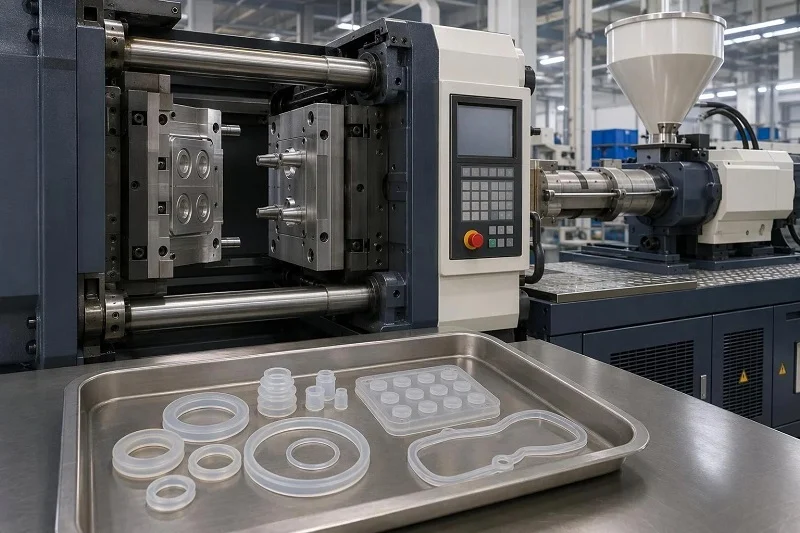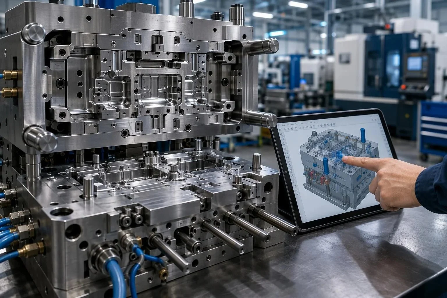
Injection molding tool design is the engineering of the mold itself — cavity and core, feed system, cooling, ejection, venting, side actions, steel and structure — so that a specified part can be produced repeatedly at target cost and quality. It sits between the part on the drawing and the machine on the floor, and it largely decides how well the two meet.
The decisions made during injection molding tool design govern part quality, cycle time, tool life, tooling cost and launch risk. A generous wall section, a gate in the wrong place or a cooling line that cannot reach a hot corner will show up as sink marks, warpage, long cycles or rejected parts long after the steel is cut. This guide separates those decisions into two groups: the part-facing details the tool must accommodate, and the tool-facing details that determine how it performs. It then follows the program through steel selection, mold trials, cost and launch risk, and closes with practical answers to the questions buyers ask most often.
Readers new to the subject can treat the first two sections as the foundation and skip ahead to tooling and production. Readers already reviewing mold designs will find the checklists and decision logic in the core tool, steel and trial sections most immediately useful.
What Is Injection Molding Tool Design?
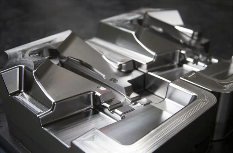
Injection molding tool design is the discipline of translating a defined part into a mold that can fill, pack, cool and eject it reliably, shot after shot, at the volume and quality the program requires. It covers the cavity and core that form the part surfaces, the feed system that delivers melt, the cooling circuit that removes heat, the ejection system that releases the part, venting, side actions for features outside the opening direction, and the steel and structure that hold it all together.
How Tool Design Differs from Part Design and Process Development
Part design sets the geometry: wall thickness, draft, ribs, bosses, hole positions and tolerances. Tool design converts that geometry into steel — deciding parting lines, gate locations, cooling layout, ejection points and side actions. Process development then finds the operating window on the machine: fill speed, transfer point, pack pressure and cooling time.
The three are sequential but not independent. A part feature that is easy to draw may be impossible to eject; a gate location chosen for cosmetics may constrain the process window. Responsibility usually sits with the part designer for geometry, the tool designer for mold construction, and the molder for process settings — but the handoffs are where misunderstandings become change orders, so each party should see the others’ decisions before they are frozen.
Why Tool Design Decisions Are Front-Loaded
The cost of a change rises steeply as a program advances. A draft angle adjusted during design review costs a conversation. The same adjustment after the cavity block is machined and heat-treated can mean re-cutting, re-polishing and re-testing the tool, with schedule consequences that dwarf the engineering time.
This is why injection molding tool design deserves attention before steel is ordered rather than after the first trial. Many of the defects that appear on trial day — drag marks, short shots, sink, warpage, flash — trace back to decisions made in the design phase: insufficient draft, an unbalanced runner, a cooling line placed too far from a hot core. Reviewing those decisions early is the cheapest quality intervention available to a program.
How Part Design Details Determine Moldability
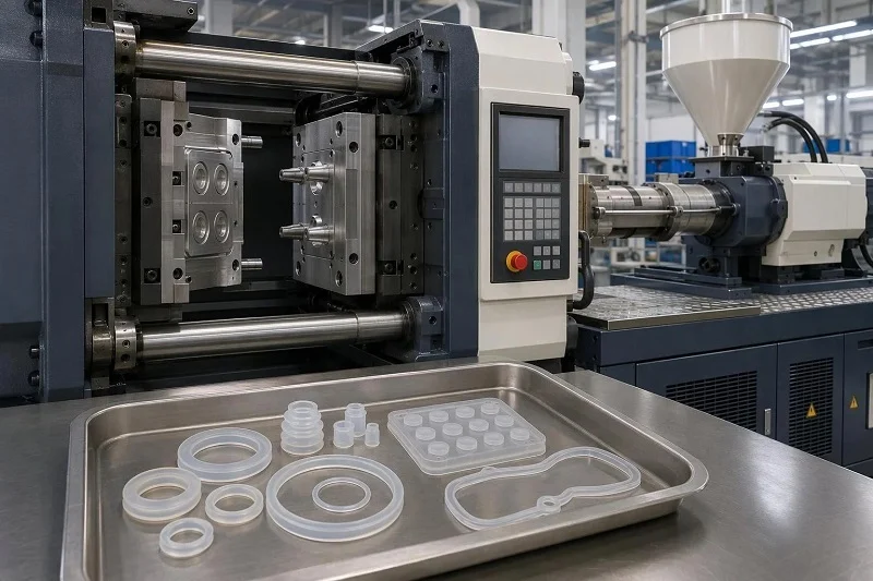
Before the tool can be designed, the part must be moldable. The details below are the part-side conditions the mold must accommodate; each carries a practical range, a mechanism that explains why the range exists, and conditions under which the range can be relaxed.
Wall Thickness and Uniformity
Cooling time scales with the square of wall thickness, so the nominal wall is the single largest lever on cycle time. Most thermoplastics mold well between roughly 1.0 and 3.5 mm, with high-flow resins such as polypropylene reaching thinner sections and low-flow polycarbonate wanting more. Where thickness must change, blend the transition over several times the step rather than jumping abruptly. Uniformity matters more than the absolute number: a part with one thick section will cool unevenly and warp regardless of how thin the rest is.
Draft Angle Requirements
Draft is the taper applied to faces that would otherwise be parallel to the direction of mold opening. Without it, the part drags and scuffs against the cavity as it shrinks onto the core, damaging the surface finish and sometimes the mold itself. A default of 1–2° per side works for most untextured surfaces; shutoffs and very shallow features can go lower, while ribs and internal bosses typically need 0.5–1.5°. Textured surfaces need substantially more — roughly 3° for light textures and 5–7° for heavy grain. Draft should be designed in from the prototype stage even when 3D printing or machining does not require it, because adding it later can change fit, form and appearance.
Radii, Ribs and Bosses
Sharp internal corners concentrate stress and are a common cause of field cracking; an internal radius of at least half the nominal wall keeps the stress concentration moderate, with the external radius set to the internal radius plus the wall so thickness stays uniform through the corner. Ribs stiffen a part far more efficiently than thick walls, so keep the rib base at roughly 0.5–0.6 times the wall and the height under about three times the wall. Bosses follow similar logic: an outside diameter of two to two-and-a-half times the screw diameter, a wall of 0.5–0.6 times the nominal wall, and a rib or gusset rather than a direct blend into a side wall. Above those ratios the junction holds enough heat that the opposite face sinks as it cools.
Holes, Undercuts and Threads
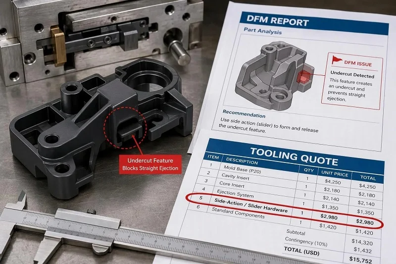
Keep hole-to-hole and hole-to-edge spacing at roughly twice the hole diameter, and watch core pin aspect ratio: a blind pin is usually kept under about 3:1 length-to-diameter, while a pin shut off at both ends can run to about 5:1 before it deflects and the hole comes out tapered. Undercuts require a side action, lifter or unscrewing core unless the resin is flexible enough to bump off a shallow feature. External threads split cleanly across the parting line; internal threads need an unscrewing or collapsible core. Every side action adds tooling cost, maintenance and a tolerance stack, so each one should be challenged at design review.
Core Tool Design Details: Cavity, Feed, Cooling and Ejection
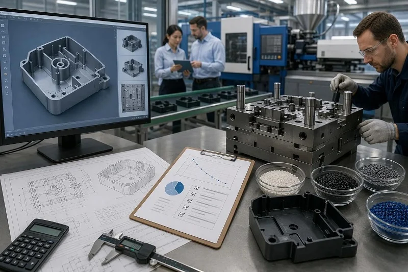
With the part established, the tool subsystems follow in a logical sequence. Each decision below has consequences that reach into cycle time, part quality and maintenance, so the guidance is framed around how the choice is made rather than a single correct answer.
Cavity and Core Layout and Cavity Count
Cavity count follows annual volume, cycle time, machine size, tolerance requirements and tooling budget. As a rough guide, single-cavity tools suit low and prototype volumes, one to four cavities cover most mid-volume programs, and higher cavitation becomes attractive once annual demand reaches the tens of thousands. More cavities reduce machine hours per part but raise tool cost and make balanced fill harder to achieve. Runner layout — H-pattern, star or naturally balanced — should be chosen so all cavities fill at the same time and pressure, because an unbalanced tool produces parts that differ from cavity to cavity.
Feed System: Sprue, Runner and Gate Design
The feed system delivers melt from the nozzle to the cavity. Cold runners are simpler and cheaper but generate scrap; hot runners eliminate runner waste at higher tooling cost and add thermal control complexity. Gate type and location affect fill patterns, packing, weld line position and cosmetic appearance: a gate placed on a visible surface leaves a mark, while one placed to fill a long section from the thick end improves packing. Gate freeze-off sets the maximum useful pack time, because once the gate seals, additional hold pressure no longer reaches the cavity. Feed system design is often where tool design and process development meet, so gate decisions should be made with the molder in the room.
Cooling System Design and Conformal Cooling
Cooling typically accounts for 50–80% of the molding cycle, and it also drives warpage and dimensional stability, because uneven cooling means uneven shrinkage. Cooling line diameter, depth from the part surface and pitch between lines should follow established guidelines so heat is removed uniformly. Tall cores, deep pockets and confined spaces are the classic problem areas, where straight drilled lines cannot get close enough and hot spots develop. Conformal cooling, built by additive manufacturing so channels can follow the part profile, shows the most benefit exactly in those cases and little advantage on simple, flat, well-cooled parts. Simulation can predict hot spots before steel is cut and is a practical way to decide whether conformal cooling is worth the investment.
Ejection System Design
Ejection strategy follows part geometry. Ejector pins suit flat, robust surfaces; sleeves suit cylindrical bosses; stripper plates suit thin-walled containers and parts where pin marks are unacceptable; lifters handle undercuts on the moving half. The design question is where force can be applied without leaving visible marks, pushing through the part or distorting it. Ejection marks, pin push-through and distortion are design issues, not just process issues: a part with insufficient draft or an ejection point on a thin wall will struggle no matter how the press is set.
Venting and Side Actions
Air trapped in the cavity must escape as the melt arrives, or it compresses, heats and leaves burn marks, or blocks fill and causes short shots. Vents belong at the last points to fill, along parting lines and at the top of deep features, and they must be shallow enough to let air out without letting melt in. Side actions — slides, lifters and split cavities — form features that lie outside the opening direction. Each one adds tooling cost, maintenance and a tolerance stack, and each should be challenged at design review: sometimes a small geometry change removes the need for a slide entirely.
Tool Steel, Mold Class and Construction Standards
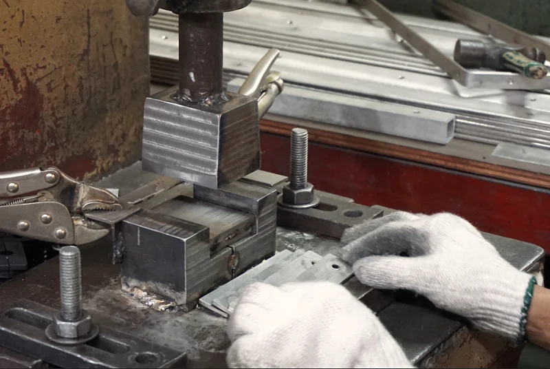
Steel and construction decisions set tool life and tooling cost, and they should be matched to the program rather than chosen by habit. A prototype tool and a high-volume production tool are built to different standards, and the classification systems below exist to make that expectation explicit between customer and toolmaker.
Choosing Mold Steel by Resin, Volume and Finish
The right mold steel balances production volume, resin abrasiveness, corrosion risk, required surface finish and tooling budget. P20, pre-hardened to roughly 28–32 HRC, is a cost-effective general-purpose choice for unfilled commodity resins and lower-to-medium volumes, with typical tool life in the range of about 100,000 to 500,000 shots. H13, heat-treated to about 48–52 HRC, suits high-volume and abrasive or high-temperature resins, with typical life from about 500,000 shots upward. S136, also about 48–52 HRC after heat treatment, is chosen for corrosive resins, optical parts and mirror finishes, where its corrosion resistance and polishability justify the higher cost. Critical zones such as gates, inserts and hot-runner areas may warrant a higher grade than the mold body.
SPI Mold Classes and What They Mean for Your Program
The SPI classification system runs from Class 101, built for a million-plus cycles with hardened cavities and cores, guided ejection, wear plates and parting-line locks, down to Class 105, a prototype tool rated for a few hundred shots. Classes 102 through 104 step down in hardness and features between those poles. Choose the class from lifetime volume, resin abrasiveness, tolerance and budget, then write it into the purchase order so customer and toolmaker share one expectation.
Construction Details That Affect Tool Life
Durability usually fails at the details rather than the cavity. Confirm mold base hardness, guided ejection, wear plates on slides, corrosion protection around cooling channels, parting-line locks, and lifting and pry-bar provisions at design review. Cooling-channel corrosion is the quiet one: it can reduce cooling efficiency over the mold’s life, potentially affecting part quality and increasing cycle time.
Production Considerations Before and During Mold Trials

Design approval is a milestone, not the finish line. Between sign-off and production ramp, the tool must be quoted against complete inputs, sampled under a structured process, and documented well enough that a different shift or press can reproduce the approved part.
Information a Toolmaker Needs at RFQ Stage
An accurate quote needs 3D CAD, 2D drawings with tolerances and datum schemes, the resin and grade, annual and lifetime volumes, finish and texture requirements, color and cosmetic criteria, assembly context, documentation or regulatory needs, and the target timeline. Missing inputs force the toolmaker to pad the price against unknowns or to issue change orders once the gaps surface.
Mold Trials, Sampling and Validation
Trial shots prove the tool and develop the process. A structured sampling run includes a short shot study to confirm balanced fill, a viscosity curve to find the speed range where the process is insensitive to small shifts, a gate seal study that weighs parts against increasing pack time, and a cooling time study. Together they define a documented window, which is what separates a tool that made a good part on trial day from a process that holds in production.
Documentation and Sign-Off Before Ramp
Before release, the file should hold the approved mold design, steel types and hardness records, trial reports, dimensional and cosmetic approval, the documented process window with its upper and lower boundaries, and a maintenance and spare-parts plan. This is risk reduction: when a dimension drifts months later, the baseline exists to trace it.
How Tool Design Drives Cost, Cycle Time and Launch Risk

The earlier sections describe individual decisions. This one ranks them, because injection molding tool design choices do not carry equal weight in the business case.
Where Cost Actually Accumulates
Tooling is a capital item; per-part cost is machine rate times cycle time divided by cavity count, plus material, scrap and maintenance. The largest levers are wall thickness, side-action count, cavity count and finish specification. Polishing to a mirror grade is among the most expensive line items on a mold quote, and adding a slide brings its own tooling and maintenance cost, while a slightly thinner wall cuts both cycle and material at once.
Cycle Time Levers in the Tool
Wall thickness dominates, because cooling time scales with its square. Cooling design then determines how close the tool gets to that theoretical floor, and gate seal sets how long pack must run. Ejection and mold-open time are small by comparison, so effort spent chasing them rarely pays back the way a cooling or wall-thickness change does.
Reducing Launch Risk Through Design Review
A working agenda covers draft and ejection, cooling and predicted hot spots, feed and gate location, every side action and whether it can be designed out, tolerances and datum scheme, steel and finish, and the trial plan. The review is the cheapest hour in the program: a change there costs a drawing revision, while the same change after steel is cut costs rework and schedule.
Conclusion about Injection Molding Tool Design
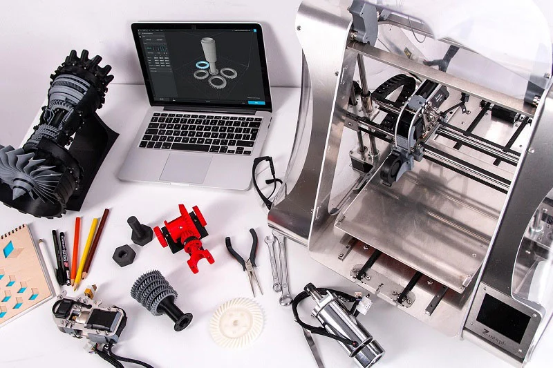
Injection molding tool design is where part quality, cycle time, tool life and launch risk are largely settled. Wall thickness sets the cooling floor, draft and ejection decide whether parts release cleanly, the feed system governs packing and weld lines, and steel and mold class fix how long the tool survives. Almost all of these choices are cheap at the design review and expensive once steel is cut, which is why the discipline rewards front-loaded attention rather than late correction.
A short prioritized action list for your next program:
- Lock part geometry, nominal wall and draft before tool design starts, and design draft in even while prototyping by 3D printing or machining.
- Review cooling layout and feed system together, with simulation where hot spots or long flow paths are likely.
- Match steel grade and mold class to lifetime volume, resin abrasiveness and required finish, and confirm the construction details that protect tool life.
- Challenge every side action and ask whether the undercut can be redesigned away.
- Insist on documented trials with a process window, dimensional and cosmetic approval, and a maintenance and spare-parts plan before ramp.
Where a single partner covers design support, prototyping, tooling and production, those handoffs happen inside one quality system rather than across several suppliers, which reduces the risk of design intent being lost between stages.
Selecting NOBLE to Support Injection Molding Tool Design

NOBLE is a China-based contract manufacturer and Sino-British joint venture, recognized by the government as a National High-tech Enterprise, with more than 10 years of manufacturing and rapid prototyping experience. Its service capability and machining expertise support customers through prototyping and volume production, and its scope runs from design to assembly rather than production alone.
Design-to-Assembly Service Scope
The chain covers design support and manufacturability input, prototyping, tooling support, production, finishing, and assembly. Keeping those steps under one roof removes the handoffs where a design intent, a tolerance callout or a finish requirement tends to get reinterpreted by a new supplier.
Quality Systems and Certification
NOBLE holds ISO 9001:2015 and ISO 13485:2016 certification. The first signals a documented quality management system; the second provides a framework suited to medical device work. Certification alone does not guarantee a specific part’s outcome, but it supports the inspection discipline and documentation practices this guide describes.
From Prototype to Volume Production
Prototyping and manufacturing capabilities under one provider let a design move from validation samples into production tooling without restarting the supplier relationship. Customers can engage by submitting CAD files and an RFQ with the inputs listed earlier, so the response reflects the real scope.
FAQs about Injection Molding Tool Design
Short answers to the questions that come up most often during injection molding tool design reviews.
What draft angle should I specify?
Use 1–2° per side on untextured surfaces as a default, with 0.5° strongly advised on vertical faces and about 3° minimum at metal-on-metal shutoffs. Textured surfaces need more: roughly 3° for light texture and 5° or more for heavy grain. Final values depend on material, depth, shrink and finish.
How many cavities should a tool have?
Cavity count follows annual volume, cycle time, machine capacity, tolerance and budget. As guidance rather than a rule: a single cavity suits low and pilot volumes, one to four cavities covers roughly 1,000 to 100,000 parts, and above that a hardened high-cavitation tool usually wins on unit cost.
Which mold steel should I choose?
Match steel to lifetime volume, resin aggressiveness and required finish. P20 (roughly 28–32 HRC) suits general-purpose, unfilled commodity resins at lower volumes; H13 (about 48–52 HRC after heat treatment) handles high-volume, abrasive or high-temperature resins; S136 (similar hardness) is chosen for corrosive resins, optical parts and mirror finishes. Gates, inserts and hot-runner zones may justify a higher grade than the mold body.
When is conformal cooling worth it?
Conformal cooling earns its cost where straight drilled lines cannot reach the hot zones: deep pockets, tall slender cores and confined spaces. On simple, flat, well-cooled parts it usually adds little over conventional channels. Cooling simulation is the practical way to decide, because it predicts hot spots and lets you compare layouts before steel is cut.
What information do I need to provide for a tooling quote?
Supply 3D CAD and 2D drawings with tolerances and datum scheme, the resin and grade, annual and lifetime volume, surface finish and texture requirements, color and cosmetic criteria, assembly context, any regulatory or documentation needs, and your target timeline. Missing inputs force the toolmaker to pad the quote or price change orders later.
How are mold trials and validation documented?
A structured trial records short-shot, viscosity, gate-seal and cooling-time studies, dimensional and cosmetic approval, and the resulting process window with its upper and lower limits. The documentation should let another press or shift reproduce the process, not just repeat a single setpoint sheet that happened to work on trial day.