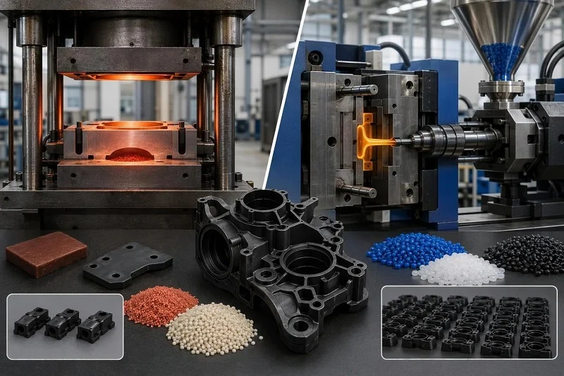
The compression molding vs injection molding decision rarely turns on a single property. It turns on whether a part geometry, a material family and a production volume can all be satisfied by the same process at a cost that works. A part that is easy to mold in one process may be impossible in the other, and a material that is routine in one may be unavailable in the other at any sensible price.
This comparison works through process flow, materials, processing parameters, tooling, design rules, applications and volume economics in that order, so the reasoning builds rather than jumping to a verdict. Compression molding is treated here primarily as a thermoset and composite process built around sheet molding compound (SMC) and bulk molding compound (BMC). Injection molding is treated primarily as a thermoplastic process that also runs BMC in specialized automated setups. The two are not interchangeable substitutes at the same specification, and the sections below say where each one wins and where it loses.
Compression Molding vs Injection Molding at a Glance
| Dimension | Compression Molding | Injection Molding |
| Process type | Open-mold, charge-placement, high-volume thermoset process | Closed-mold, metered-shot process, most commonly thermoplastic |
| Material familiesa | SMC and BMC: polyester resin with chopped glass, fillers and additives | Filled thermoplastics such as glass-filled nylon; BMC in specialized automated setups |
| Typical cycle time | SMC cures in about 30–150 s; overall cycles as low as 60 s | Injection speeds of 1–5 s; full cycle dominated by cooling |
| Tooling | Expensive but very durable metal dies; forged steel dies can run as many as 200,000 SMC parts | Closed mold with cavity, runner, gating, cooling and ejection; cost scales with cavity count |
| Pressure range | About 24.5–172.4 bar (500–2,500 psi) for SMC | About 5,000–12,000 psi for BMC injection |
| Geometry limits | Charge must reach all sections; complex undercuts need side actions or post-machining | Gate location and flow-length-to-thickness ratio govern fill |
| Volume sweet spot | Described as appropriate above roughly 10,000 parts | Wide range; per-part cost falls as cavity count and volume rise |
| Typical applications | Exterior body panels, Class A surfaces, high-volume composite parts | Consumer products, medical equipment components, industrial parts |
Read the table as a set of typical windows, not specifications for any single part. A cycle time, pressure or volume figure here describes the conditions under which it was reported; your part’s wall thickness, charge pattern, material grade and tool design will move every number.
How the Two Processes Work: A Step-by-Step Flow Comparison
The two processes differ first in how material reaches the cavity, and second in what happens to it once it is there.
The Compression Molding Cycle, Step by Step
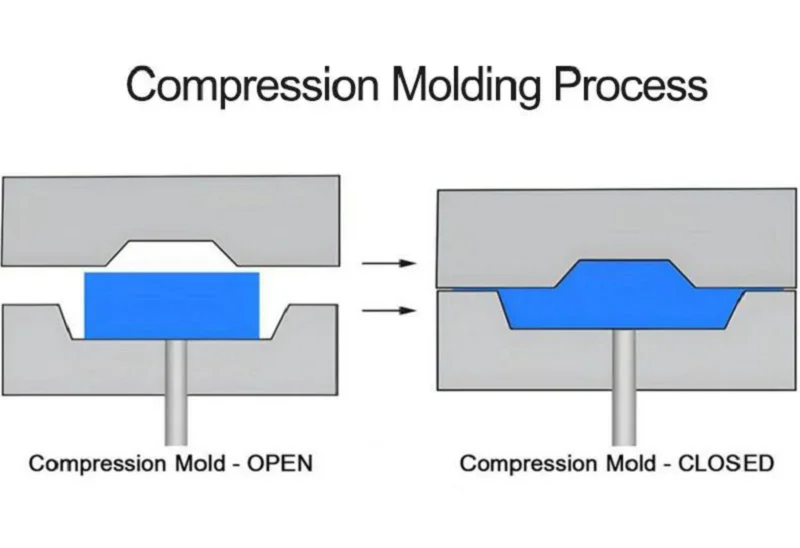
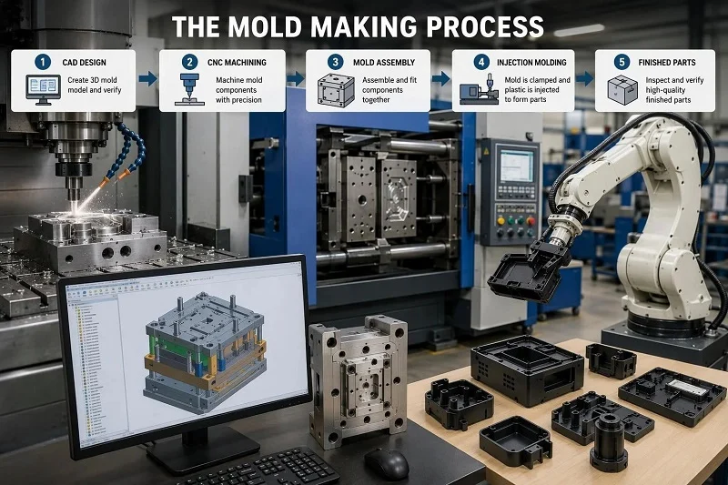
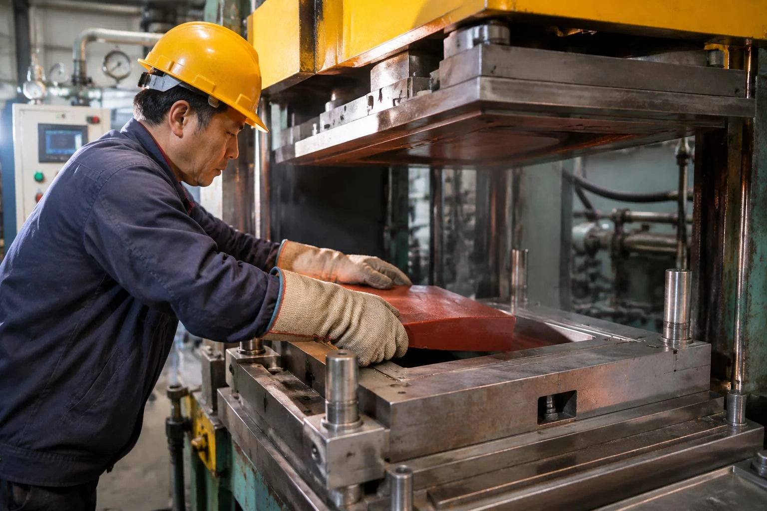
SMC arrives as a leather-like sheet, is cut into smaller sheets, and the charge pattern (ply schedule) is assembled on a heated mold at roughly 121–262 °C. The mold closes and clamps, pressure of about 24.5–172.4 bar is applied, material viscosity drops and the compound flows to fill the cavity. After cure the part is demolded manually or by integral ejector pins. Fiberglass thermoset SMC cures in about 30–150 seconds, with overall cycles as low as 60 seconds — figures specific to SMC, not to every compression-molded material.
The Injection Molding Cycle, Step by Step
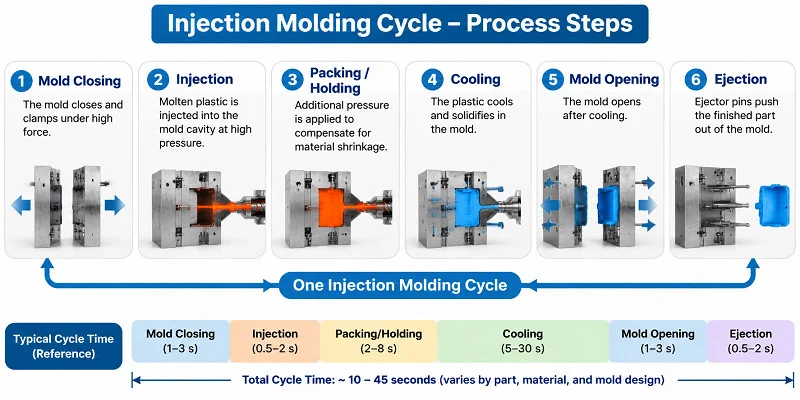
Injection molding begins with drying and feeding, then a ram- or screw-type plunger plasticates the polymer and forces a metered shot through a heated barrel into a closed, heated mold at roughly 5,000–12,000 psi for BMC. The melt flows along runner channels, cures or cools, and is ejected with minimal finishing. Injection speeds are typically one to five seconds, and as many as 2,000 small parts per hour can come off some multiple-cavity molds. Injection molding most commonly runs filled thermoplastics; automated BMC injection has taken over some markets previously held by thermoplastics and metal casting.
Where the Two Flows Diverge in Practice
The structural consequences matter more than the headline cycle times. Compression molding is an open-mold, charge-placement process: labor enters at charge assembly and demolding, and part-to-part consistency depends on how consistently the charge is cut and positioned. Injection molding is a closed-mold, metered-shot process: the machine controls shot size, and ejection is automated, but runners and gates generate scrap that must be trimmed or reground. Compression cycles are cure-dominated; injection cycles are cooling-dominated. Those divergences drive the tooling, design-rule and volume-economics sections that follow.
Materials: What Each Process Can and Cannot Run
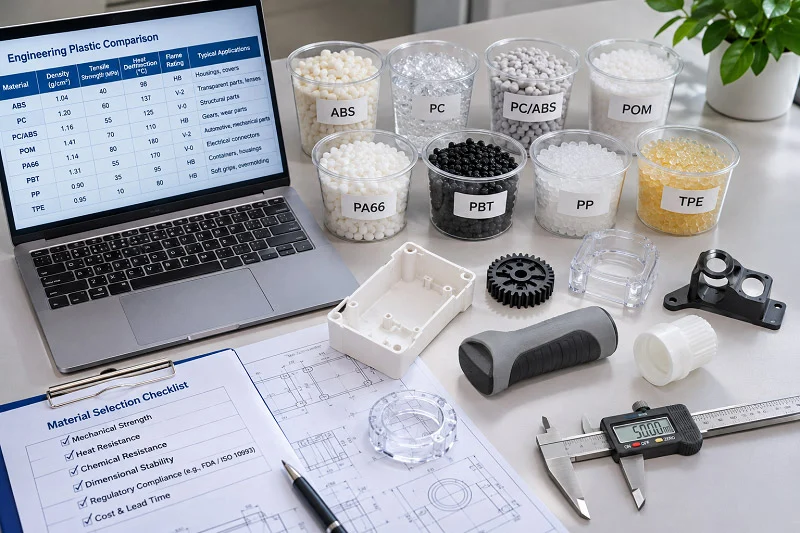
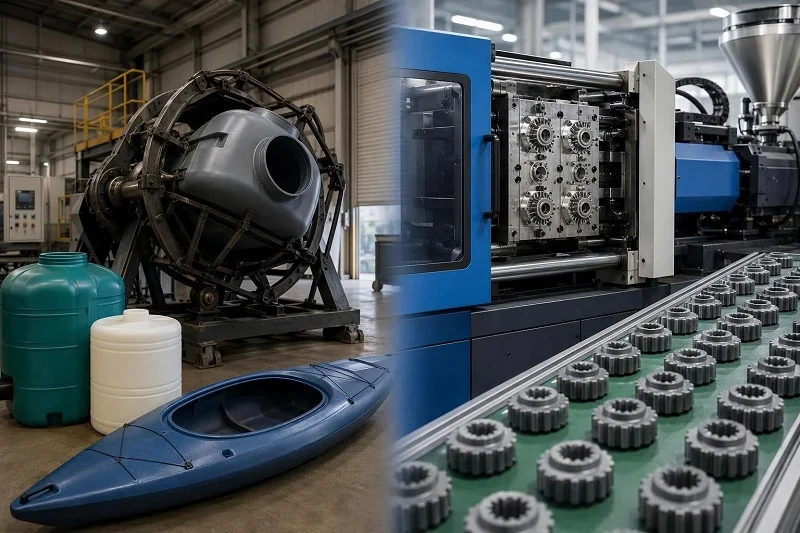
The material split is the deepest difference between the two processes: compression molding is built around thermosets and composite charge materials, injection molding around thermoplastics with a specialized BMC capability. That split constrains chemistry, recyclability and dimensional behavior more than any single property comparison.
Materials Commonly Run in Compression Molding
Compression molding centers on SMC and BMC — polyester resin systems carrying chopped glass, fillers and additives. Formulation latitude is wide: low-profile and Class A grades, low-density, flexible and pigmented versions, and toughened grades aimed at preventing microcracking that can cause paint “pops.” A typical low-profile Class A SMC formulation is, by weight, about 25 percent polyester resin, 25 percent chopped glass, 45 percent fillers and 5 percent additives — meaning most of the recipe is filler and reinforcement, which is what delivers stiffness, surface quality and dimensional stability rather than polymer toughness. Carbon-fiber-reinforced SMC for exterior body panels is described as under exploration, not established production.
Materials Commonly Run in Injection Molding
Injection molding is led by filled thermoplastics such as nylon with chopped glass fiber, and covers a very broad base of commodity and engineering resins. Because the polymer melts and cools rather than reacting, scrap can in principle be reprocessed, and cooling under pressure supports tight dimensional control. BMC also runs through automated injection setups; the dimensional stability reported for a specially formulated BMC in electronic throttle control valves belongs to that specific application and should not be generalized to all BMC parts.
Materials That Effectively Point to One Process
As a directional guide: a requirement for a thermoset or composite charge with high filler and reinforcement content points toward compression molding; thick cross-sections in BMC can be compression-molded or transfer-molded; a thermoplastic resin system points toward injection molding. This is not an exclusive rule — a material family common in one process is not forbidden in the other — so confirm the specific grade and part with the processor before committing tooling.
Processing Key Points: Parameters That Decide Part Quality

The two processes are controlled by different variables: compression molding by charge pattern, mold temperature, pressure and cure time; injection molding by melt temperature, injection pressure and velocity, mold temperature, cooling time and clamp force. A parameter window from one cannot be transplanted into the other.
Key Compression Molding Parameters
Charge weight and charge pattern placement decide whether the cavity fills evenly and where knit lines land. Mold temperature (SMC-typical roughly 121–262 °C) governs flow and cure rate; applied pressure (roughly 24.5–172.4 bar) drives fill and controls surface finish and sink; cure time (30–150 seconds for fiberglass thermoset SMC) must be long enough to develop strength before demolding. These ranges are SMC-typical illustrations, not universal compression molding specifications.
Key Injection Molding Parameters
Injection temperature and mold temperature are material-specific: ABS runs at roughly 200–260 °C injection with a 40–60 °C mold, POM at roughly 180–230 °C with an 80–120 °C mold. Required injection pressure rises with flow difficulty and thinner walls — for ABS, from about 80–110 MPa for easy-flow, heavy sections up to 150–200 MPa for thin-wall parts. Cooling time scales with wall thickness squared, and clamp force must exceed the separating force generated by injection pressure over the projected area.
Why the Parameter Sets Are Not Interchangeable
A thermoset cures by chemical reaction and cannot be re-melted, so time-at-temperature and pressure during cure govern the outcome. A thermoplastic solidifies by cooling, so thermal management and shrinkage compensation govern the outcome. That is why a compression molding pressure window means nothing on an injection machine, why cooling time dominates injection cycles while cure time dominates compression cycles, and why drying and moisture control belong to the injection side of the comparison.
Tooling: Cost, Lead Time and What Drives Each
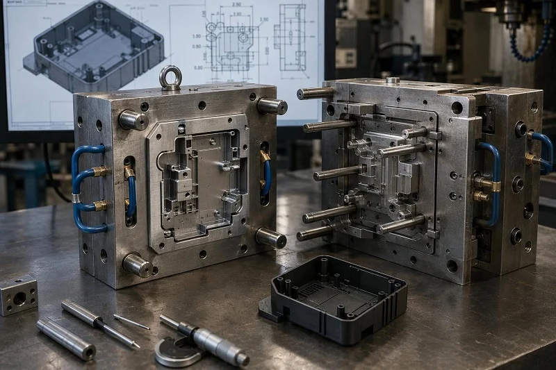
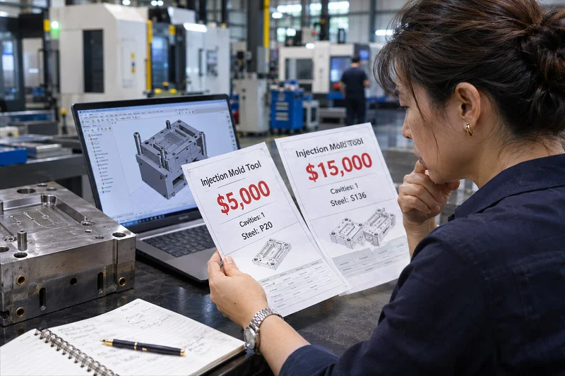
Tooling is where the two processes diverge most sharply on budget. Compare tool material and durability, complexity ceiling, expected life, cost drivers, lead-time drivers, and how each interacts with volume.
Compression Molding Tooling
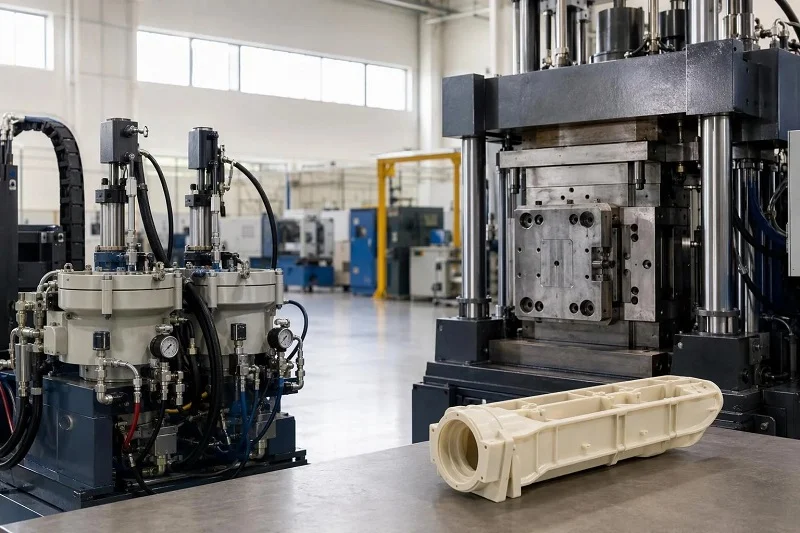
Compression molding uses durable metal dies built for high-volume thermoset work. A set of forged steel dies can turn out as many as 200,000 parts with SMC, and compression molding is described as appropriate when production quantities exceed 10,000 parts. Cost and lead time are driven by die size and complexity, surface finish requirements, heating provisions and the durability needed for the intended run. The 200,000-part figure is a capability statement for forged steel dies with SMC, not a guarantee for every tool.
Injection Molding Tooling
Injection tooling is a closed mold with cavity, runner and gating system, cooling provisions, ejection and a clamping interface. Cost drivers are cavity count, part size and projected area, gating complexity, cooling design, surface finish and expected shot count. Cavity count trades tool cost against per-part cost and cycle time, and machine selection is coupled to tool design: injection capacity, shot volume, clamp force, plasticizing capacity and clamp stroke must all be checked against the cavity requirements.
Comparing Tooling Economics Side by Side
Compression tooling is described as expensive but very durable, so its economics depend heavily on whether the volume exists to amortize it. Injection tooling cost scales strongly with cavity count and part complexity, while per-part cost falls as volume rises. There is no universal winner: compression favors long runs of a stable part, injection favors designs where cavity count and cycle time can be pushed hard.
Design Rules: How Part Geometry Changes Between the Two Processes

Geometry constraints follow from how material enters and leaves the mold. The same part concept can therefore need different draft, wall thickness, charge or gate placement, and insert strategy depending on which process shapes it.
Draft, Wall Thickness and Flow Length
Compression molding fills by charge flowing under pressure across the cavity, so charge pattern design and avoiding thin sections the charge cannot reach uniformly matter most. Injection molding fills through runners and gates, so gate location, wall thickness consistency and flow-length-to-thickness ratio set the limits. Specific values remain material- and part-dependent.
Undercuts, Inserts and Ejection
Compression-molded parts are demolded manually or by integral ejector pins, and complex undercuts generally require side actions or post-machining. Injection molding ejects automatically and accepts inserts placed in the cavity before the shot, which often consolidates parts and removes assembly steps.
Gates and Runners vs Charge Placement
Injection molding design work centers on gate location and runner balance, because runners and gates generate scrap that must be trimmed or reground. In compression molding the ply schedule and charge pattern replace the gate as the tool for controlling fill, so design work centers on charge weight, shape and placement.
Applications: Where Each Process Is Actually Used
Application territory is best organized by what each process does well rather than by industry label, since the same industry may use both. The two also overlap in a narrow band where substitution is an engineering judgment.
Typical Compression Molding Applications
Compression molding occupies high-volume thermoset and composite work: exterior body panels and other automotive parts, including Class A surface applications where low-profile SMC formulations apply. Industrial manufacturers often formulate resins and compound SMC in-house to meet UV, impact, moisture and surface-quality demands. Carbon-fiber SMC for body panels is described as under exploration rather than established production.
Typical Injection Molding Applications
Injection molding covers high-volume thermoplastic parts across consumer products and industrial equipment; one NIST study notes that injection-molded components make up roughly 42 percent of toys and 33 percent of medical equipment components. Automated BMC injection has also taken over some markets once held by thermoplastics and metal casting, such as electronic throttle control valves previously die-cast in aluminum, where a specially formulated BMC supplied dimensional stability in that specific application.
Overlap and Substitution Cases
The genuine competition sits with BMC parts: thick cross-sections can be compression-molded or transfer-molded, and many BMC parts can also be injection-molded. Volume, geometry, surface finish requirement, dimensional tolerance and tooling availability tip the decision, and substitution remains a case-by-case judgment rather than a default.
Volume, Cycle Time and Cost: When Injection Molding Becomes the Cheaper Route
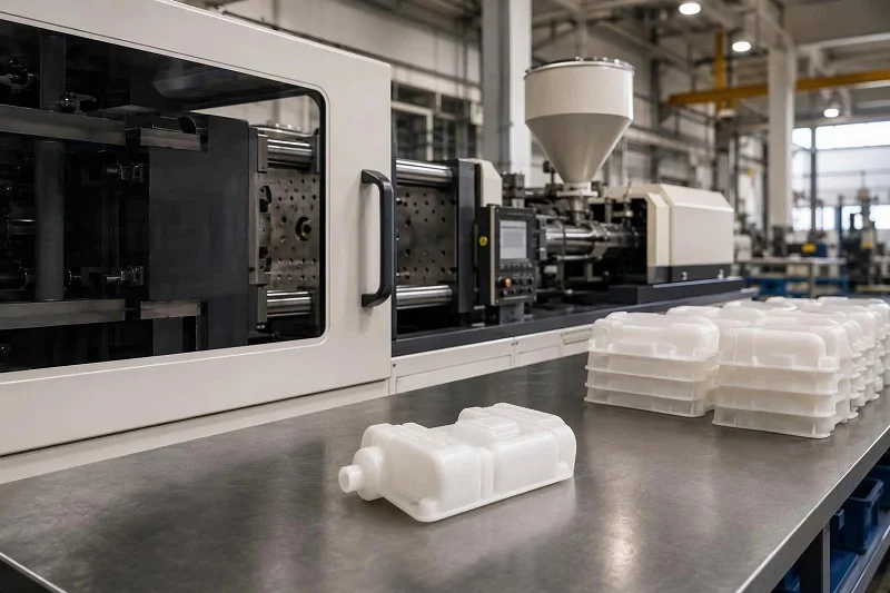
Per-part cost is the sum of amortized tooling, material, machine time, labor and scrap, and compression molding vs injection molding weight those components very differently. Compression molding carries expensive, durable tooling and low material waste; injection molding carries cheaper per-cavity tooling but adds runner scrap, drying and trimming. That is why the cheaper route depends on the run, not the process name.
Cycle Time and Throughput Compared
Fiberglass thermoset SMC cures in about 30 to 150 seconds, with overall cycles as low as 60 seconds, while injection speeds run one to five seconds and some multiple-cavity molds produce up to 2,000 small parts per hour. These are different quantities: cure time, injection time and full cycle. Comparing them without cooling, ejection and handling misleads.
Tooling Amortization and the Crossover Point
Compression molding is described as appropriate when production quantities exceed 10,000 parts, and a set of forged steel dies can turn out as many as 200,000 SMC parts, spreading tooling investment over a long run. Injection molding’s per-part cost falls as cavity count and volume rise, but tooling cost rises with cavity count. There is no single universal crossover volume; part size, material, cavity count and scrap value decide it, so plug your own figures into a quote rather than trusting a threshold.
Choosing Between Compression Molding and Injection Molding
Treat the decision as a short sequence of questions, and let each answer narrow the field.
What material family does the part require?
A thermoset or composite charge with high filler and reinforcement content points to compression molding; a thermoplastic resin system points to injection molding. Where the requirement is BMC, both routes stay open and the remaining questions decide.
What geometry and surface finish are needed?
Large, relatively uniform panels with Class A surfaces suit compression molding, while small, intricate parts with tight tolerances and molded-in inserts favor injection molding.
What production volume is expected over the tool’s life?
Compression molding is described as appropriate above roughly 10,000 parts, and its expensive, durable dies reward long runs. Injection molding amortizes cheaper tooling faster but adds runner scrap and drying.
What tooling budget and lead time are available?
A single-cavity compression die can be simpler to justify than a multi-cavity injection tool, but a complex die with heating provisions and high surface-finish demands will cost more and take longer.
Who should choose which: readers with large thermoset or composite parts, Class A cosmetic surfaces and volumes in the tens of thousands point to compression molding. Readers with thermoplastic parts, tight dimensional tolerances, molded-in inserts and high cavity counts point to injection molding. Where a specific material grade or volume forecast is still unconfirmed, confirm it with the processor before committing to tooling.
Why Choose NOBLE for Injection Molding

NOBLE is a Chinese contract manufacturer recognized for strong service capability and professional processing expertise, and that combination helps customers move efficiently from prototyping through volume production. We hold ISO 9001:2015 and ISO 13485:2016 certification, and we provide a full service scope from design to assembly rather than production alone. If you are weighing compression molding vs injection molding for a project, our team can help you confirm the material grade, review the design for manufacturability and plan the tooling route. Send us your drawings and requirements to start the conversation.
FAQs of Compression Molding vs Injection Molding
These answers cover the questions readers most often raise after working through the comparison. Each one is scoped to the conditions under which it holds, and the relevant section above carries the full reasoning.
Which process fits my part geometry, material and volume?
A thermoset or composite charge with high filler content, large panels and runs above roughly 10,000 parts point to compression molding; a thermoplastic part with tight tolerances, inserts and high cavity counts points to injection molding. See Choosing Between Compression Molding and Injection Molding.
How do the two process flows differ step by step?
Compression molding assembles a charge pattern on a heated open mold, closes and clamps it, lets the charge flow and cure, then demolds. Injection molding dries and plasticates resin, injects a metered shot into a closed heated mold, cools, ejects and trims runners and gates.
Which materials are effectively limited to one process?
Thermoset SMC and BMC charge materials are built for compression molding, while commodity and engineering thermoplastics are built for injection molding. BMC can run through automated injection setups, so the split is directional rather than absolute.
Which processing parameters matter most in each?
Compression molding is governed by charge weight and pattern, mold temperature, pressure and cure time; injection molding by melt temperature, injection pressure and velocity, mold temperature, cooling time and clamp force.
What drives tooling cost and lead time?
For compression dies, size, complexity, surface finish, heating provisions and required durability; for injection molds, cavity count, part size and projected area, gating, cooling design and expected shot count.
At what volume does injection molding become cheaper per part?
There is no universal threshold. Compare amortized tooling, material, machine time, labor and scrap for your part size, material, cavity count and scrap value.
How do design rules differ?
Compression molding design centers on charge weight, shape and placement, with manual or ejector-pin demolding; injection molding centers on gate location, runner balance, wall thickness consistency and automated ejection with inserts.