Reaction injection molding is a low-pressure process in which two reactive liquid components are metered, impingement-mixed, and injected into a closed mold, where they polymerize into the finished part. That single sentence separates it from ordinary thermoplastic injection molding, which melts solid pellets and forces them into a steel cavity under high pressure. In reaction injection molding the mold does not shape a melt; it holds a reacting liquid while the chemistry builds the material.
The distinction drives everything downstream — the tooling you can afford, the part sizes you can reach, the cycle times you must plan for, and the volumes at which the economics work. This guide walks through the process step by step, sets out the case for choosing reaction injection molding alongside the case against it, surveys the material families (polyurethane, polyurea, hybrids, and the reinforced RRIM and SRIM variants), and compares the process head-to-head with thermoplastic injection molding, structural foam molding, compression molding, casting, blow molding, metals, and fiber-reinforced composites. It closes with design and processing guidelines and a decision framework for when reaction injection molding is the right process, when it is not, and how to design parts that mold well.
What Is Reaction Injection Molding and How Does It Differ from Ordinary Injection Molding?
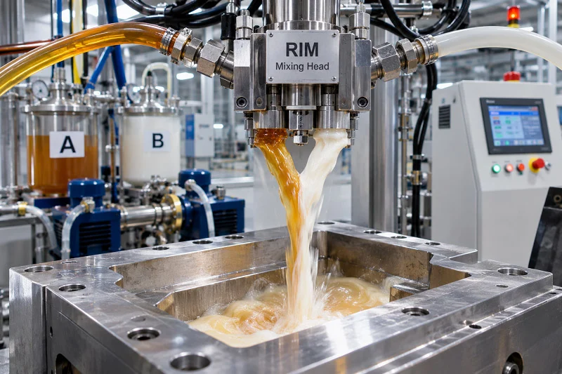
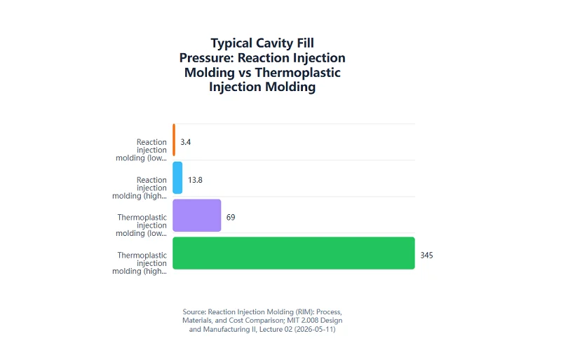
Reaction injection molding is a low-pressure process in which two reactive liquid streams — typically an isocyanate “A-side” and a polyol or resin “B-side” — are metered, impingement-mixed, and injected into a closed mold where they polymerize and cure. Filling pressures sit in the range of roughly 50–200 psi (3.4–13.8 bar), and the components enter the cavity as low-viscosity liquids rather than as molten polymer.
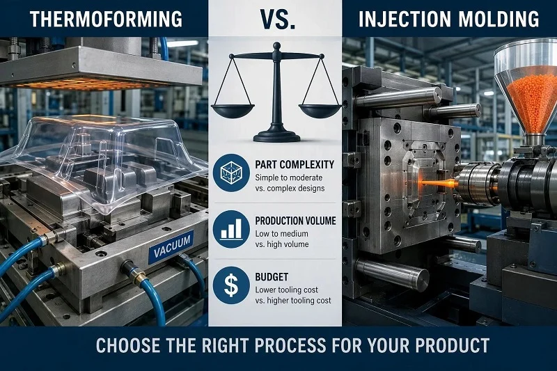
Thermoplastic injection molding works the other way around. Solid pellets are melted at high temperature and packed into a steel mold at injection pressures commonly cited between 5,000 and 20,000 psi. Because clamp force is the product of cavity pressure and projected area, that pressure difference is what makes large reaction injection molding parts feasible on modest presses and in comparatively inexpensive tooling.
The name invites confusion, so keep both halves separate. “Reaction” refers to the chemistry: the part is created by polymerization inside the mold, not by cooling a melt. “Injection” refers only to delivery: the liquid mix is forced into a closed cavity. The process family began with polyurethane reaction injection molding, developed in the late 1960s and adopted by the automotive industry in the 1970s for fascias and body panels; it has since expanded to polyurea, polyisocyanurate, reinforced (RRIM), and structural (SRIM) variants.
The chemistry at the center of reaction injection molding
In reaction injection molding the part is formed by polymerization, not solidification. An isocyanate group reacts with a polyol hydroxyl group to form a urethane linkage; water or a blowing agent can generate gas to produce an integral-skin foam; diamine chain extenders push the system toward polyurea. The reaction is exothermic, and gel time, cure rate, and demold time are governed by the catalyst package and the formulation rather than by chilling the mold.
That is why the processing window looks nothing like a thermoplastic window. In thermoplastic molding, cooling time generally dominates the cycle and the mold acts as a heat sink. In reaction injection molding, the mold is held at a controlled temperature (typically 100–180 °F / 40–80 °C) and water lines manage the exotherm, but the clock is set by how fast the formulation gels and builds green strength. The same basic chemistry, reformulated with different polyol functionality, chain extenders, and blowing agents, spans soft elastomers, semi-rigid integral-skin foams, and rigid structural foams.
Why low pressure changes the tooling equation
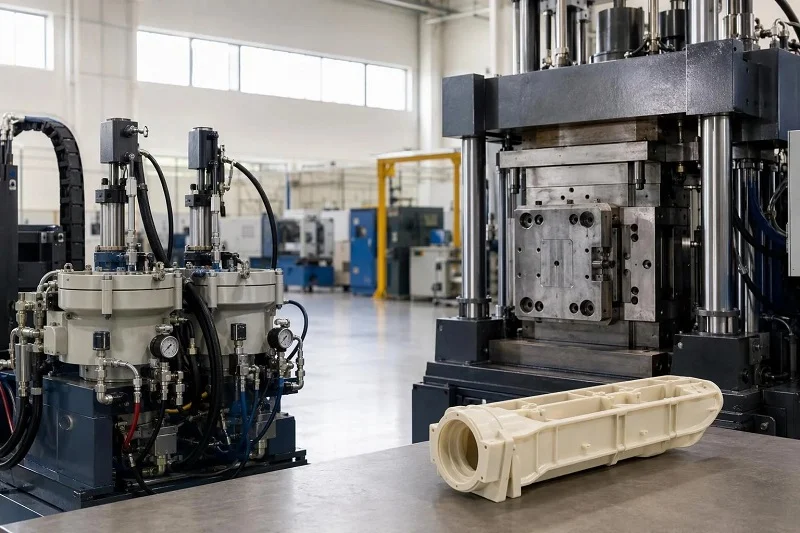
Cavity pressure in typical reaction injection molding stays under about 100 psi (7 bar). At that level, cast aluminum, electroformed nickel, kirksite alloys, epoxy, silicone, and fiberglass tools become viable where a hardened steel injection mold would be required for the same large part. Tool material selection then becomes a trade among the number of parts to be made, dimensions and tolerances, surface quality and texture, required mold life, mold cost, and part performance — and the savings grow with mold size.
The trade-off is the heart of every reaction injection molding decision. Tooling is cheaper, but the per-part cost is higher: two-component liquid chemistry costs more per pound than commodity pellets, cycles run in minutes rather than seconds, and most parts need trimming, flash removal, and painting. The process is an arbitrage between upfront tooling and ongoing piece price, and the arithmetic in the next section shows how to evaluate it.
The Reaction Injection Molding Process, Step by Step
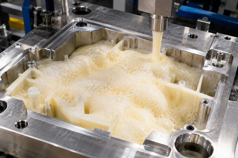
The sequence from raw material to finished part is where time, cost, and quality risk actually sit. Typical figures — injection time on the order of 15–20 seconds, parts cured in about a minute, cycle times commonly 4–6 minutes, and no post-cure needed for some systems — are starting points, not guarantees. They shift with part size, wall thickness, and formulation, and larger parts trend toward the longer end.
Metering and conditioning the two components
Pressurized day tanks hold the isocyanate and the polyol, with recirculation pumps and agitators maintaining a homogeneous blend and heat exchangers holding each component at its target temperature. Ratio control is the critical variable: the stoichiometry of the isocyanate-to-polyol reaction determines crosslink density and final properties, and an off-ratio shot cures to the wrong hardness no matter what the mold does. Temperature matters for the same reason — it changes viscosity, and viscosity changes how well the two streams mix.
Fillers such as milled glass or minerals, added to the polyol side, require continuous agitation to stay in suspension. Moisture is a contaminant throughout, because isocyanates react with water to form urea linkages and carbon dioxide gas; that reaction is useful when deliberately used to blow a foam and unwanted when it introduces voids or property drift.
Impingement mixing in the mixhead
High-pressure pumps drive both streams at roughly 1,500–3,000 psi (100–200 bar) into a self-cleaning mixhead, where they collide head-on in a small chamber. There is no mechanical mixer; the jets themselves do the mixing in milliseconds. For fast-reacting systems this is essential, because the blend must be homogeneous before gel begins. Mixhead design, nozzle condition, and flush cycles between shots are recurring operational concerns, and a worn or poorly cleaned mixhead shows up as streaking and inconsistent parts.
Filling the mold: laminar flow, orientation, and venting
The velocity of the material transfers from turbulent to laminar flow as it passes the dam gate, and the low-viscosity liquid then fills the cavity in laminar flow. Mold orientation and vent placement therefore determine whether air is displaced properly rather than trapped. Gating into the lowest point in the tool is the standard rule, paired with the shortest practical flow length; vents must be sized for the air the incoming liquid pushes ahead of it.
This is also where two design rules later in the guide originate. Gradual wall transitions help the flow front advance evenly, and adequate draft matters because the part is hand-pulled and polyurethane grips the tool.
Cure, demold, and finishing
Inside the mold the reaction proceeds through exotherm, gel, and the point at which the part has enough green strength to be demolded without distortion. Then comes the finishing reality: trimming, flash removal, and painting are normal cost lines for reaction injection molding. As-molded surfaces generally require painting rather than delivering a Class A finish straight from the tool, although in-mold coating — paint sprayed onto the mold surface before filling — can reduce post-mold finishing labor and produces excellent coating adhesion.
Some production setups have compressed demold to 60–150 seconds for large Class A parts using multi-press carousel arrangements with robotic handling. Treat that as an advanced production configuration, not a baseline expectation; a conventional reaction injection molding cell should be planned around the multi-minute cycle.
Why Choose Reaction Injection Molding?

The case for reaction injection molding is a set of distinct advantages, each with a mechanism and each paired with a cost. Weighing them honestly is what turns the process from a brochure into a decision.
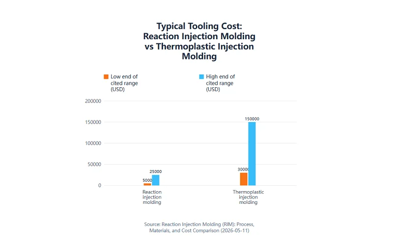
Indicative tooling ranges for reaction injection molding versus thermoplastic injection molding, as cited in the article. Figures are typical practitioner estimates that depend on part size, tool material and complexity, not quotations.
The advantages: low tooling cost for large parts; large, lightweight, thin-walled parts made feasible by low viscosity and low clamp force; design freedom for intricate geometry; variable wall thickness within a single part; good impact, chemical, and weatherability properties depending on formulation; and integral-skin foam capability, where a dense skin forms over a low-density core.
The limitations: higher per-part material cost, longer cycles, limited recyclability because the part is a thermoset, an as-molded surface that generally needs paint, and a volume sweet spot that tops out well below thermoplastic injection molding. Frame the choice as an economic one — tooling arbitrage versus per-part cost — and the break-even logic follows: divide the tooling cost difference by the per-part cost difference to find the break-even quantity, then compare that against lifetime program volume, not first-year volume.
Tooling cost and the volume economics of reaction injection molding
Indicative ranges commonly cited put reaction injection molding tooling at roughly $5,000–$25,000 against $30,000–$150,000 for traditional injection molding, a reduction often described as 60–80% lower. These are indicative figures that depend on part size, tool material, and complexity — a large Class A tool with in-mold coating capability will not sit at the bottom of the range.
The volume window is commonly described as roughly 100 to 5,000 parts per year, with some sources extending the upper bound to about 10,000 units per year before cycle time erodes the economics. Run the arithmetic for your own part: if the reaction injection molding tool saves $100,000 and the piece price runs $2 higher, the break-even quantity is 50,000 parts — which may exceed the entire program. If the tool saves $100,000 and the piece price runs $0.50 higher, break-even falls to 200,000 parts, and the answer depends entirely on lifetime volume. The formula is simple; the inputs are specific to your part, so the conclusion is too.
Large parts, low clamp force, and design freedom
Cavity pressure under about 100 psi means clamp force stays modest even as projected area grows to several square meters, so large presses are not required and parts can be several square meters in area. The flowability of the low-viscosity components distributes material evenly inside the mold, which supports large, thin-walled, and intricately detailed parts.
Variable wall thickness is a genuine differentiator. Cross sections from about 0.25 in to 1.125 in within the same molded part are cited for reaction injection molding — a range that is not true for thermoplastic injection molding, blow molding, or sheet molding compound. Inserts can also be placed in the cavity and encapsulated; because fill pressure is low, inserts need far less support against washout than in injection molding, which is a real advantage for large bonded assemblies and for parts that carry sensors, wiring, or reinforcing frames.
Where reaction injection molding is the wrong choice
The negative case deserves equal clarity. Reaction injection molding is the wrong process when volumes exceed roughly 10,000 units per year and cycle time dominates the cost model; when the design requires engineering thermoplastics such as PEEK, PPS, or polycarbonate; when a Class A surface is required without painting; and when tolerances tighter than about ±0.005 in are needed. In those cases thermoplastic injection molding with steel tooling is the correct route.
Between roughly 2,000 and 5,000 units, the decision requires detailed cost modeling rather than a rule of thumb: tooling amortized over lifetime volume, per-part material cost, cycle time multiplied by machine rate, and secondary operations such as painting for reaction injection molding. That gray zone is where a careful spreadsheet, not a preference, should decide.
Material Selection for Reaction Injection Molding
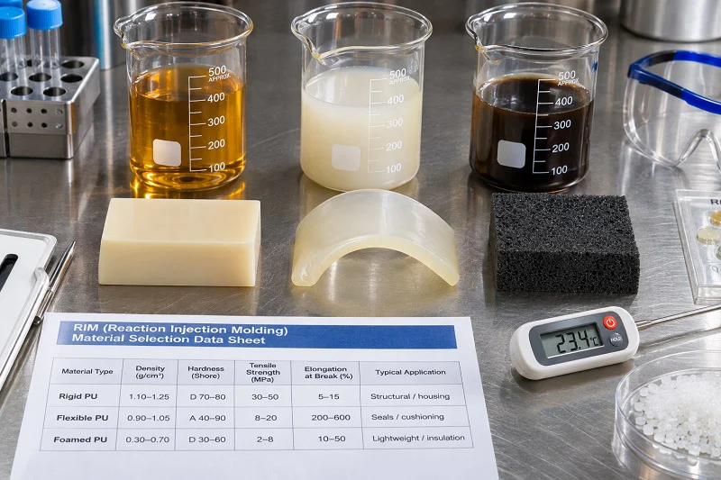
Material selection in reaction injection molding starts with a survey of the families and then narrows through a sequence of engineering questions. The dominant material is polyurethane, available across an extremely wide range of stiffness, hardness, and density — from flexible elastomer to rigid structural foam. Polyurea offers fast reactivity and relative insensitivity to moisture. Polyurethane-polyurea hybrids balance cure speed against property profile, and polyisocyanurate systems trade some flexibility for thermal stability and flammability resistance. Reinforced variants — RRIM, with milled glass or mineral fillers typically at 10–25% by weight, and SRIM, with a preplaced glass mat in the cavity — raise stiffness and thermal resistance. DCPD (polydicyclopentadiene) is a distinct reaction injection molding system with its own property profile, capable of large parts in low-pressure molds with mechanical performance similar to injection-molded engineering thermoplastics.
The selection criteria are stiffness and modulus, impact and elongation, heat resistance, chemical and UV resistance, surface finish and paintability, foam versus solid, and filler or reinforcement level. One principle governs all of them: formulation — isocyanate type, polyol backbone, chain extender, catalyst, and additives — drives properties more than the process does. Aromatic isocyanates yellow under light exposure, while aliphatic systems are light-stable; that single choice can decide whether a part can be used unpainted outdoors.
Polyurethane systems: from flexible elastomer to rigid structural foam
Soft elastomers, semi-rigid integral-skin foams, and rigid structural foams all come from the same basic chemistry, differentiated by polyol functionality, chain extenders, and blowing agents. Rigid polyurethane systems generally have higher flexural modulus and hardness and offer good thermal resistance, electrical properties, chemical resistance, and acoustical insulation; elastomeric systems are chosen where impact strength, toughness, and abrasion, wear, and cut resistance matter. The two categories overlap at the boundary, so flexural modulus ranges are not a clean dividing line.
Structural foam systems use a blowing agent that activates as the polyol reacts with the isocyanate, producing a higher-density skin over a lower-density microcellular core. Polyurethane foams range from as little as 2 pounds per cubic foot to as much as 55 pounds per cubic foot, and flexural modulus rises with density — an unreinforced structural foam at 15 lb/ft³ is cited at roughly 30,000 psi. That integral-skin structure is a reaction injection molding advantage: stiffness where the part needs it, low weight where it does not, and a surface that can be painted as molded.
Polyurea and hybrid systems
Polyurea’s fast reactivity and relative insensitivity to moisture made two-component polyurea spray elastomers useful coatings for large surface area projects, and the chemistry carries into molded elastomer parts. Because the reaction is fast, polyurea systems can shorten demold, but the same speed narrows the processing window and puts a premium on mixhead performance and ratio accuracy.
Hybrid polyurethane-polyurea systems exist precisely to balance those trade-offs, and interpenetrating polymer network approaches have been used to modify reaction rate, maximum exotherm, and resin viscosity alongside the property profile. Keep the claims scoped: these are formulation-dependent characteristics, not universal rankings, and the specific system data sheet governs.
Reinforced reaction injection molding: RRIM and SRIM
RRIM mixes fillers — milled glass, mica, wollastonite, talc, processed mineral fibers — into the polyol stream before injection. SRIM places a glass mat or preform in the cavity before the resin is injected, so the reinforcement is structural rather than dispersed. What reinforcement buys is higher flexural modulus (commonly cited at 2–4× unfilled polyurethane for RRIM), better dimensional stability, and higher thermal resistance. What it costs is processing complexity, and for SRIM, added labor for mat placement.
A third route, long-fiber injection, chops and wets out glass fibers inside the mixhead and sprays the mix onto an open mold by robot before the mold closes. It combines reaction injection molding materials with something closer to sheet molding compound processing and is worth asking about when high glass content and structural performance are both required.
A practical material selection checklist
Work through the questions in order. First, define the mechanical and thermal load case the part must survive, including the temperatures it will see in processing, assembly, and end use. Second, decide solid versus integral-skin foam — foam cuts density and weight, but it changes stiffness and surface behavior. Third, decide unreinforced versus reinforced, and if reinforced, whether dispersed filler (RRIM) or a preplaced mat (SRIM) suits the geometry and volume. Fourth, check chemical exposure — solvents, degreasers, cleaning agents, household products — and UV and flammability requirements. Fifth, confirm paintability and surface requirements, including whether in-mold coating is an option. Sixth, confirm that the chosen formulation is available and processable at your molder, with the equipment and experience the system demands. This is ordinary engineering reasoning, not a sourced rule, but skipping a step is how projects end up with a material that meets the data sheet and not the application.
Reaction Injection Molding vs Other Manufacturing Processes
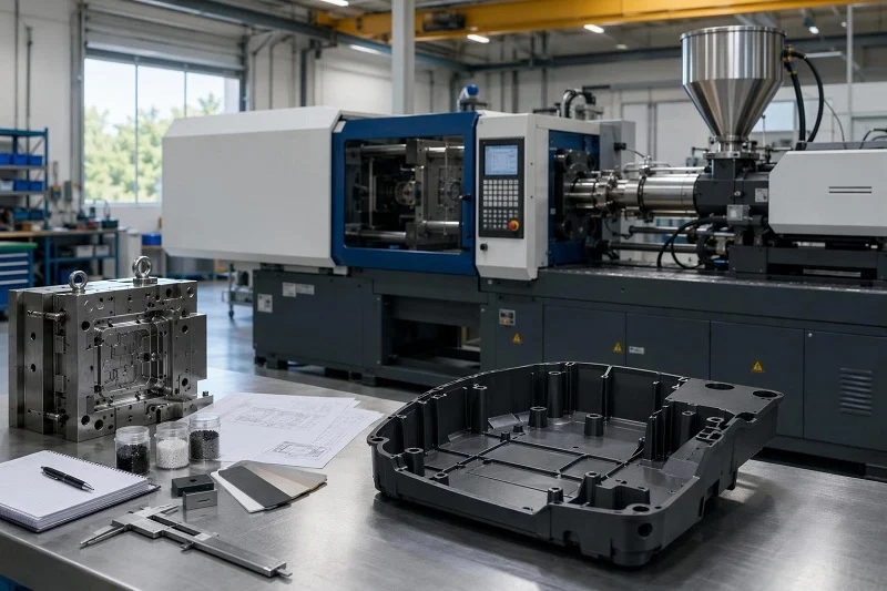
Comparisons are only useful when they are scoped to the criteria where the difference is real. The framework here is tooling cost, cycle time, part size, volume window, surface finish, material options, and recyclability. The table below collects indicative figures; treat them as typical values rather than specifications, because ranges overlap at the boundaries and every part shifts the numbers.
| Criterion | Reaction injection molding | Thermoplastic injection molding |
| Injection pressure | 50–200 psi | 5,000–20,000 psi |
| Typical tooling cost | $5,000–$25,000 | $30,000–$150,000 |
| Cycle time | 2–10 minutes | 10–60 seconds |
| Material options | PU, polyurea, DCPD, reinforced variants | 100+ thermoplastics |
| Maximum part size | 6+ ft (2 m) feasible | Limited by press tonnage |
| Volume sweet spot | ~50–5,000 units/year | ~1,000–1,000,000+ units/year |
| As-molded surface | Generally requires painting | Class A achievable |
| Recyclability | Thermoset; not regrindable | Reground and reused |
Cavity fill pressure ranges for reaction injection molding and thermoplastic injection molding, converted to a common unit (bar). The ranges differ by roughly fivefold at the closest comparison and about a hundredfold at the widest, or roughly twenty- to twenty-five-fold between corresponding ends of each range, which is what makes low-cost tooling and low clamp force possible in reaction injection molding. Ranges are typical process windows, not requirements.
Reaction injection molding vs thermoplastic injection molding
This is the central comparison. Reaction injection molding fills at 50–200 psi, tools commonly at $5,000–$25,000, cycles in 2–10 minutes, molds polyurethane, polyurea, and DCPD, reaches parts over 2 m, and is competitive roughly between 50 and 5,000 units per year. As-molded surfaces generally need paint, and the part is a thermoset that cannot be reground. Thermoplastic injection molding fills at 5,000–20,000 psi, tools commonly at $30,000–$150,000, cycles in 10–60 seconds, offers more than a hundred thermoplastics, is limited in size by press tonnage, and is competitive from about 1,000 to over 1,000,000 units per year; Class A is achievable and scrap is regrindable.
The decision usually turns on part size and volume together. For parts larger than about 12 inches at low volume, reaction injection molding often has no viable thermoplastic alternative, because a large-format injection mold may require a press of 1,000 tons or more. At high volume on a small part, the cycle-time advantage of thermoplastic molding compounds and the answer flips.
Reaction injection molding vs structural foam molding
Both processes produce large, stiff, lightweight parts with a skin-core structure, which is why they get confused. Structural foam molding is a thermoplastic process: a gas, most commonly nitrogen, is dissolved in the melt, a short shot is injected, and the expanding gas completes the fill. Reaction injection molding creates the skin-core structure through the reaction itself at low pressure, and reaction injection molding structural foam is sometimes called “rigid” reaction injection molding.
The historical record describes reaction-molded integral-skin urethane foams as becoming competitive with thermoplastic structural foams, and that framing still holds: choose reaction injection molding when you want the skin-core structure in a large part with low-cost tooling, and structural foam molding when a thermoplastic resin and its property set are the requirement.
Reaction injection molding vs compression molding
Compression molding of SMC or BMC places a pre-measured charge in an open heated mold and squeezes it shut under 15–30 MPa of clamp force. It delivers strong, heat-resistant, electrically stable parts and is cheaper to tool than injection molding for parts larger than a shoebox, but it requires a pre-measured charge and high-pressure presses. Reaction injection molding’s advantage is lower pressure and cheaper tooling for large parts; compression molding’s advantage is fiber-reinforced structural performance and cycle economics at higher volumes. If the part is a structural panel with high glass content and the volume is substantial, compression molding deserves serious consideration; if the part is large, geometrically complex, and needed in modest quantity, reaction injection molding usually wins on tooling.
Reaction injection molding vs casting and blow molding
Casting uses simple, low-cost tooling and slow cycles and is limited to relatively simple shapes and lower volumes — rule it in only when geometry is simple and quantity is small. Blow molding produces hollow thermoplastic parts and belongs to an entirely different geometry class; it is not a substitute for a solid reaction injection molding part. Both comparisons are about exclusion rather than exhaustive treatment.
Reaction injection molding vs metals and fiber-reinforced composites
Stamped or machined metal brings higher density and a different stiffness-to-weight profile, but mature tooling and joining ecosystems that are hard to beat for certain structural brackets. Against fiber-reinforced composites, the comparison is partly internal: SRIM is itself a reaction injection molding variant, so the real question is whether mat-placement labor buys enough structural stiffness to justify itself. Sheet molding compound and glass mat thermoplastic offer laminated reinforcement and, for GMT, short cycles, but both require high-pressure equipment. Reaction injection molding’s lower pressure reduces press and tooling cost, and its ability to mold details, grids, and bosses into the B-side of a Class A part keeps it competitive on complexity.
Design and Processing Guidelines for Reaction Injection Molding Parts
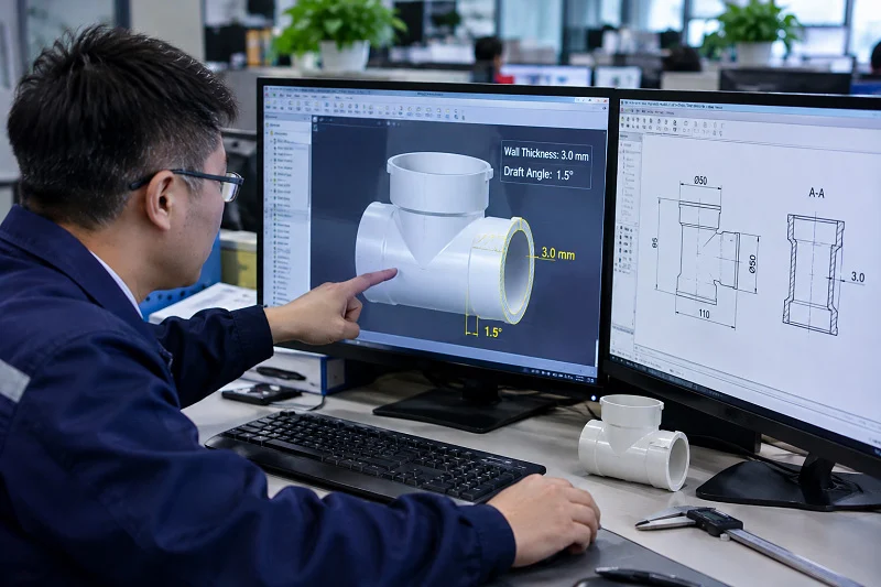
The rules of thumb below determine whether a design molds well. They are recommendations with reasons, not absolute requirements, and should be confirmed with the molder and the specific formulation.
| Feature | Recommended | Limit | Why |
| Wall thickness | 0.125–0.250 in (3–6 mm) | 0.100–0.500 in (2.5–12 mm) | Chemistry-driven cure tolerates thick sections |
| Wall transition | Gradual taper | Abrupt 3:1 step | Isolated heavy masses run hot during the exotherm |
| Draft | 2–3° per side | 1° | Polyurethane grips the tool; parts are hand-pulled |
| Internal radius | 0.125 in (3 mm) or more | — | Structural corners and flow-front smoothness |
| Rib base | 0.6–0.75 × wall | — | Low-viscosity fill makes ribs easy; skin still sinks |
| Cavity pressure | Under about 100 psi (7 bar) | — | Sets the low clamp force and cheap tooling |
| Part area | Up to several square meters | — | Clamp force scales gently with projected area |
Wall thickness, transitions, and rib design
The exotherm is the reason behind the wall rules. Thick sections generate more heat, and an isolated heavy mass surrounded by thin walls cannot shed it into the surrounding material, so it runs hot, cures differently, and can sink or distort. Gradual transitions distribute that heat and keep the flow front advancing evenly. The chemistry-driven cure is what tolerates thick sections in the first place — 0.100–0.500 in is a practical range, and sections up to 12 inches are possible in some DCPD systems — but tolerance is not indifference.
Ribs fill easily because the liquid is so fluid, which is an advantage over thermoplastic molding. Sink marks remain a skin-effect risk, so a rib base of 0.6–0.75 × the nominal wall manages the trade-off between stiffness and surface quality. Where extra strength is needed, adding ribs is generally better than dramatically increasing wall thickness.
Draft, radii, and ejection
Draft matters more here than in thermoplastic molding because parts are hand-pulled and polyurethane grips the tool. Two to three degrees per side is recommended and 1° is a practical minimum; deeper ribs and cavities require more draft, so keeping them as shallow as possible reduces the requirement. Internal radii of 3 mm or more serve both structural corners and flow-front smoothness, and a common rule sets the outside radius at about 1.5 times nominal wall and the inside radius at about 0.5 times nominal wall. Break sharp painted edges with a small radius, because uniform paint coverage over a sharp outside corner is difficult to achieve.
Mold temperature, cycle time, and venting
Mold temperature typically runs 100–180 °F (40–80 °C), injection time around 15–20 seconds, cure in about a minute, and cycle time typically 4–6 minutes. Venting must be sized for the air displaced during laminar fill; inadequate venting shows up as short shots, burn marks, and inconsistent surfaces. Larger parts trend toward the longer end of the cycle range, and thick structural foam sections may need 8–10 minutes for sufficient green strength before safe removal. Some systems need no post-cure; others require ambient post-cure over 24–48 hours to reach full specified mechanical properties, so confirm the requirement before planning downstream operations.
Choose NOBLE to Support Your Reaction Injection Molding Project

NOBLE is a China-based contract manufacturer with strong service capability and professional processing capability that help customers complete prototyping and mass production efficiently. We are certified to ISO 9001:2015 and ISO 13485:2016, and we offer a full scope of service from design to assembly — not just production.
For a reaction injection molding project, that scope matters at the handoffs. Design support and prototyping come first, so the geometry, wall transitions, draft, and material choice are settled before tooling is cut. Tooling coordination follows, then production, inspection, and assembly — all under one roof. The practical benefit is a single partner across the prototype-to-production transition, which reduces handoff risk and shortens the path from design intent to qualified parts.
If you are evaluating reaction injection molding for a large housing, a structural panel, or an assembly that needs inserts and finishing, send us the drawing and the expected volume. We will help you work through the process and material questions in this guide against your specific part.
FAQs About Reaction Injection Molding
What is the difference between reaction injection molding and ordinary injection molding?
Ordinary thermoplastic injection molding melts solid pellets and forces them into a steel mold at 5,000–20,000 psi. Reaction injection molding meters two reactive liquids, mixes them by impingement, and injects them at roughly 50–200 psi into a closed mold where they polymerize. The part is created by chemistry rather than by cooling a melt. See the first section for the full contrast.
What materials can be used in reaction injection molding?
Polyurethane dominates, spanning flexible elastomers, integral-skin foams, and rigid structural foams. Polyurea, polyurethane-polyurea hybrids, polyisocyanurate, and DCPD are also used, along with reinforced variants — RRIM with milled glass or mineral fillers and SRIM with a preplaced glass mat. The material section covers the selection criteria.
What is the typical cycle time?
Commonly 4–6 minutes, with a broader range of 2–10 minutes depending on wall thickness, formulation, mold temperature, and part complexity. Thin-wall parts with fast-reacting polyurea formulations can demold in 2–3 minutes; thick structural foam sections may need 8–10 minutes. Advanced carousel setups have compressed demold to 60–150 seconds for large Class A parts.
What volumes make reaction injection molding economical?
Commonly described as competitive between roughly 100 and 5,000 parts per year, with some sources extending the upper bound to about 10,000 units per year. The reliable method is to divide the tooling cost difference by the per-part cost difference to find the break-even quantity, then compare it with lifetime program volume. Between about 2,000 and 5,000 units, detailed cost modeling is warranted.
Can reaction injection molding produce Class A surfaces?
As-molded surfaces generally require painting rather than delivering a Class A finish straight from the tool. In-mold coating — paint sprayed onto the mold surface before filling — provides excellent adhesion and can reduce post-mold finishing, and textures are reproduced faithfully from the tool. Plan painting as a cost line unless in-mold coating is specified.
What wall thicknesses are practical?
Recommended 0.125–0.250 in (3–6 mm), with practical limits of 0.100–0.500 in (2.5–12 mm). The chemistry-driven cure tolerates thick sections, and cross sections from about 0.25 in to 1.125 in within the same part are cited. Avoid abrupt transitions, because isolated heavy masses run hot during the exotherm.
What is the difference between RRIM and SRIM?
RRIM mixes fillers such as milled glass or minerals into the polyol stream before injection, dispersing reinforcement throughout the part. SRIM places a glass mat or preform in the cavity before the resin is injected, creating a structural composite. RRIM is simpler to process; SRIM delivers higher structural performance at the cost of mat-placement labor.
Is reaction injection molding recyclable?
The part is a thermoset, so it cannot be remelted and reground like thermoplastic scrap. Runners, flash, and rejected parts go to landfill or require specialized chemical recycling. If a sustainability mandate requires closed-loop regrind, thermoplastic injection molding is the better fit.
How tight can tolerances be?
Typical tolerances run about ±0.010–0.030 in (0.25–0.75 mm), with roughly ±0.020 in (±0.5 mm) on features under 12 in and about ±0.1–0.2% of dimension on large panels. Polyurethane’s thermal expansion is high, so specify the inspection temperature. If the design needs ±0.005 in or better, thermoplastic injection molding with steel tooling is the appropriate process.