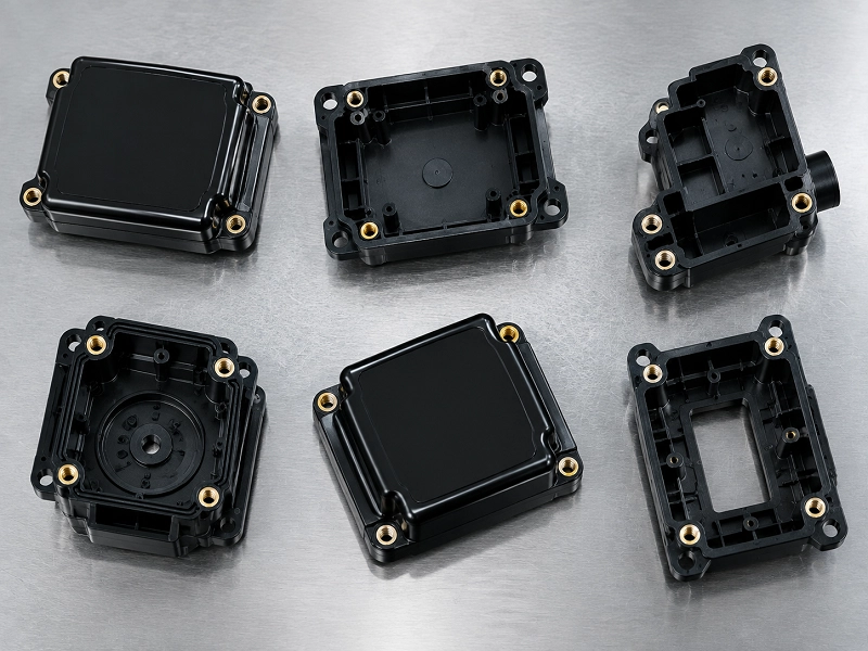
Insert molding is a common injection molding process. Many engineers understand design and products. But when facing production, they are not familiar with the process. This stops them from moving the project forward smoothly. The product cannot be delivered on time. This article will explain insert molding design from 0 to 1. It will take you from a basic to a deep understanding.
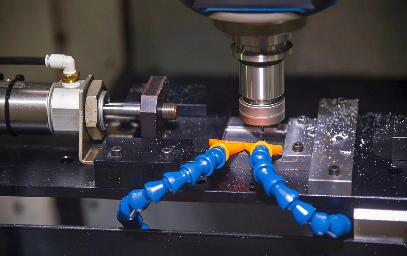
1. What is the Insert Molding Capability?
Generally speaking, insert molding means putting a metal threaded part into a plastic part. This makes the plastic part stronger and easier to use. It makes a very strong connection and avoids repeated assembly. Here is a simple explanation of how insert molding works.
1.1 Preparing the Machine
Insert molding needs a special injection molding machine. It is usually a vertical injection molding machine, designed for this process. The machine also needs a set of molding design guidelines. The engineering team must follow them.
The machine must be set to the required parameters based on the part design. This equipment has strict tolerance control. This ensures the parts made are accurate enough. If the tolerance is slightly off, the product may fail.
1.2 Placing the Insert into the Mold
When making plastic parts, several types of inserts can be used. Common ones are stainless steel, brass, or plain steel. These inserts usually have a threaded surface. This helps the plastic grip them better.
The mold is placed vertically in the machine. Inserts can be placed by CNC or by hand. Automated placement uses a robot arm to put the insert into the mold. This gives high efficiency, good consistency, and stable precision. Automatic machines are faster and can handle the high temperatures during molding.
Manual placement is good for small batch production. Someone is watching, so inspection is more careful. But manual placement can be unstable. Precision and repeatability are lower. Also, the high injection temperature is not friendly to the operator.
After the insert is placed, gravity keeps it in position during molding. Now the mold can close, and melted plastic can be injected. Injection is done under high pressure. This ensures the plastic fills every corner of the mold. It also ensures the plastic and insert bond tightly.
1.3 Molding
After everything is ready, the injection molding process begins. Molten plastic flows into the cavity, enveloping the placed inserts. The temperature should be kept stable during injection molding so that the curing is uniform.
Maintaining pressure can reduce shrinkage and also prevent plastic from flowing back into the barrel. The length of the forming cycle depends on the material properties and the size of the part.

2. What are the Points to Note Before Insert Molding Design?
2.1 Thermal Imbalance
The insert is usually metal. The plastic is a hot melt. Metal conducts heat fast. Plastic conducts heat slowly. During injection, the plastic’s heat is quickly drawn away by the metal insert. This causes the plastic around the insert to cool too early. This leads to incomplete filling, poor bonding, and even sink marks or voids. During design, consider whether the insert needs preheating and whether the mold temperature needs adjustment. The larger and heavier the insert, the more obvious the thermal imbalance. A reasonable approach is to bring the insert temperature close to the plastic melt temperature. This reduces the negative effects of temperature difference.
2.2 Flow Interruption
When the plastic melt flows in the mold, it is interrupted if it meets an insert. The melt must flow around the insert to fill other areas. If the insert position is not well designed, the melt may form a stagnant zone behind the insert. This causes incomplete filling or weld lines. Weld lines have lower strength. If they appear in stressed areas, they affect part life. During design, place the gate properly. Let the melt flow smoothly around the insert. Avoid turbulence and trapped air. If needed, adjust the insert shape to reduce flow obstruction.
2.3 Mechanical stress concentration
Plastic shrinks when cooled, but metal inserts do not. This shrinkage difference will generate stress around the insert. If the inserts have sharp corners or edges, stress will be concentrated at these locations, causing the plastic to crack. When designing, avoid sharp corners in inserts and use rounded corners for transitions as much as possible. The thickness of the plastic wall around the insert should also be uniform to avoid sudden changes in thickness. If the wall thickness is too thin, it will weaken the strength; if it is too thick, shrinkage marks are likely to occur. A reasonable approach is to maintain a uniform wall thickness around the inserts and add embossing or grooves on the surface of the inserts to make the stress distribution more even.
2.4 Insertion stability
Inserts must remain stable during the injection molding process. If the insert is not firmly fixed in the mold, the injection pressure will cause the insert to deviate, resulting in positional shift or uneven plastic wrapping. Insert offset can cause assembly difficulties and even part scrapping. When designing, it is necessary to consider how the inserts are positioned in the mold. Common methods include positioning needles, support columns, or magnetic fixation. For slender inserts, support structures also need to be added to prevent bending and deformation during injection molding. The fit clearance between the insert and the mold should also be well controlled. If it is too loose, it will shake; if it is too tight, it cannot be placed in.
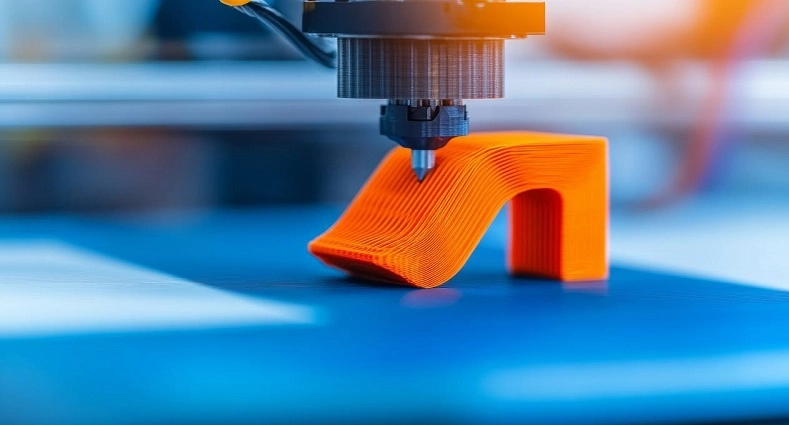
3. What are the key factors to consider in insert forming design?
3.1 Avoid Sharp Corners
Plastic shrinks when it cools. Metal inserts do not shrink. This difference creates stress around the insert. If the insert has sharp corners or edges, stress concentrates there. The plastic cracks easily. So when designing the insert, round the outer corners. Add rounded transitions to inner corners too. The fillet radius should not be too small. A minimum of 0.5mm is generally recommended. The insert surface should not have sudden steps. Keep transitions smooth. This makes stress distribution more even. The plastic does not crack easily. Part life is longer. This is the easiest point to overlook in insert design, but it has a big impact.
3.2 Optimize Draft Angle
Draft angle is the release slope. The insert itself does not need to be released. But it affects how the surrounding plastic releases. If the insert is placed vertically, the plastic wraps around it. During release, it can be scratched or stuck. So the insert shape should have a slight slope. This lets the plastic release smoothly. Also, the insert fixing position in the mold should have a slope. This makes placing and removing easier. The slope does not need to be large. Generally, 1 to 3 degrees is enough. Too small a slope makes release difficult. Too large affects insert positioning accuracy. This detail is especially important in mass production.
3.3 Design the Insert
The plug-in, or the inlay itself, should have a shape that matches its function. If providing threads, it is necessary to ensure that the thread length is sufficient, generally at least 1.5 to 2 times the diameter of the screw. If it is to provide strength, the insert must have sufficient embedding depth; if it is too shallow, it will be pulled out. The surface of the insert is usually embossed, slotted, or inverted to allow the plastic to hold it, preventing rotation and pull-off. The height of the insert should preferably be flush with or slightly lower than the plastic surface, and should not protrude to affect assembly. When designing plugins, it is also necessary to consider how they are positioned in the mold and whether there is a place to hold the positioning needle.
3.4 Proper Boss Diameter
The boss is the ring of plastic around the insert. If the boss diameter is too small, the plastic wall is too thin. The strength is not enough, and it cracks easily. If the boss diameter is too large, the plastic is too thick. It shrinks during cooling, and sink marks appear on the surface. Generally, the boss outer diameter should be at least 1.5 to 2 times the insert diameter. The plastic wall thickness around the insert should be uniform. Do not have one side thick and one side thin. If the insert is a brass nut, the boss diameter is usually calculated as the insert outer diameter plus two times the wall thickness. Wall thickness is recommended to be 1.5 to 3mm, depending on the material. If this size is not set well, problems come up easily later.
3.5 Use Durable Resin
Insert molding has requirements for plastics. The plastic must be able to withstand the high temperature during injection molding and also bond well with the inserts. Commonly used materials include ABS, PC, nylon PA, PBT, and PPS. Nylon has good strength, but it is highly hygroscopic, and its size may change. PBT and PPS have good chemical resistance and are suitable for high-demand applications. If the parts are to come into contact with chemicals or high-temperature environments, more durable resins should be selected. In addition, the shrinkage rate of plastic should also be taken into account. Materials that shrink too much are prone to creating gaps around the inserts. When choosing materials, one should not only consider their strength but also their compatibility with inserts.
3.6 Consider Metal Bonding
For plastic and metal to bond firmly, it relies on chemical bonding or mechanical bonding. Chemical bonding requires material compatibility. For instance, certain plastics have relatively good adhesion to brass. But in most cases, it relies on mechanical combination. The surface of the insert is knurled, grooved or inverted, and the plastic flows in and gets stuck after cooling, thus forming mechanical locking. When designing, the combination method should be selected based on the force conditions. If the force is large, the embedding depth and surface features should be increased. If it’s just for preventing rotation, knurling is enough. The coefficients of thermal expansion of metals and plastics should also be close; otherwise, they are prone to loosening when the temperature changes.
3.7 Mold Wall Thickness
Mold wall thickness refers to the plastic thickness around the insert and the distance from the insert to the part edge. If the wall is too thin, the strength is not enough. It cracks easily during injection. If the wall is too thick, cooling is slow, and sink marks appear. Generally, the plastic wall thickness around the insert is recommended to be 1.5 to 3mm. The distance from the insert to the part outer wall must also be sufficient. Usually, at least the same as the wall thickness. If the distance is too close, the plastic cracks easily. Wall thickness should also be as uniform as possible. Avoid sudden thickness changes. The junction of thick and thin areas is where stress concentrates. It is a high-risk area for cracking. Draw a cross-section view during design. You will find many problems.
4. What are the Materials Used in Insert Molding Design?
The insert molding process is compatible with many molding materials. Engineers and designers usually choose the most suitable material based on the final product’s specific requirements.
4.1 Thermoplastics
These materials are eco-friendly because they can be used many times. They have excellent chemical resistance. They are ideal for ensuring gloss and texture changes in the injection molding process. Here are common thermoplastic types:
- Polystyrene is a lightweight, transparent plastic with a low melting point. It resists acids and bases. So it is suitable for daily mainstream products like medical devices and consumer goods.
- This thermoplastic polymer is usually lightweight, tough, and chemically resistant. It also has dielectric and impermeability properties. Common polyethylene thermoplastics include LDPE, HDPE, and MDPE.
- Nylon is a thermoplastic polymer. It is naturally strong and durable. It also resists chemicals and wear. Its melting point is relatively high. So it is an ideal metal replacement in many applications. Because of this, nylon is widely used in heavy-duty products in manufacturing and mining.
4.2 Thermosetting Materials
Thermosetting plastics are very similar to thermoplastics. However, these plastic polymers cannot be reused or recycled. Because thermosetting plastics are not cost-effective and not eco-friendly, manufacturers rarely use them. Some common thermosetting plastics include:
- Epoxy is a thermosetting resin. It hardens and cures permanently after processing. It has no melting point. So it is very suitable for harsh application environments. Epoxy has excellent adhesion, high chemical resistance, and heat resistance.
- Phenolic resin. Phenolic resin is a thermosetting material. It has excellent chemical resistance and electrical resistance. It withstands high temperatures. It also has outstanding hardness and dimensional stability. Phenolic resin is suitable for making electrical equipment, circuit boards, and more.
4.3 Elastomers
Elastomers are natural and synthetic polymers with properties similar to rubber. Because of their excellent elasticity and recyclability, engineers use them in many fields. Their eco-friendly properties make them especially suitable for making many plastic automotive products and home appliances. Some common elastomer types include natural rubber and polyurethane:
- Natural rubber. This resin is flexible and durable. It is suitable for making tires and many home appliances.
- It has excellent wear resistance and tear resistance. This plastic has high elasticity and impact resistance. Also, its high-temperature resistance makes it more durable than most materials.

5. What are the factors of mold design for insert forming?
The core of the mold design for insert forming is to ensure that the insert can be stably, accurately, and firmly fixed in the mold. Firstly, the mold should have a reliable positioning structure, commonly using positioning pins, support columns, or magnetic fixation to ensure that the inserts do not deviate during injection molding. Secondly, the mold should take into account the placement and removal methods of inserts. For manual placement, there should be sufficient space, and for automated placement, the position for the mechanical hand to grasp should be reserved.
The position of the gate is also very crucial. The gate must not be directly facing the insert; otherwise, the direct impact of the melt will deviate the insert and also cause poor bonding. The melt should be filled smoothly around the insert to avoid the formation of a retention zone behind the insert.
The cooling system should be uniform, especially around the inserts, to prevent shrinkage marks or deformation caused by thermal imbalance. The ejection mechanism should avoid the position of the insert to prevent the insert from falling off due to force during ejection.
In addition, the mold material should be wear-resistant, as the repeated insertion of inserts will wear down the positioning structure. When the batch is large, the positioning parts should be made into replaceable inserts for easy maintenance. Only when the mold design is completed can the insert forming be stably mass-produced.

6. What are the common types of inserts used in injection molding?
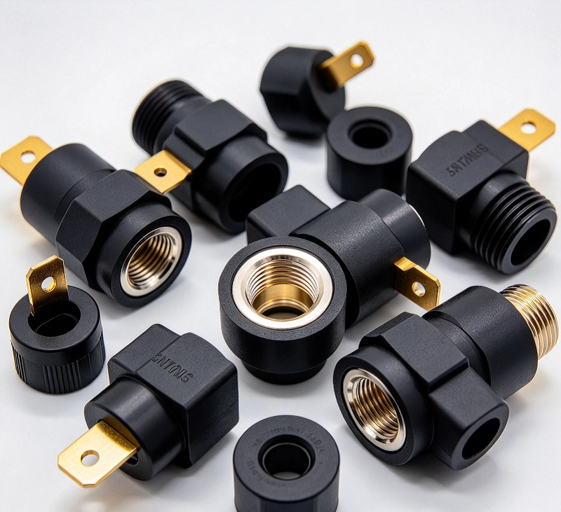
Threaded insert technology is widely used. It provides customized inserts for excellent insertion results. Usually, fasteners are made of brass. But aluminum and stainless steel are also suitable materials. These inserts can be implanted by ultrasonic insertion, molding (using insert molding technology), or heat insertion.
However, the insert molding process has better mechanical properties, faster production speed, and higher precision. Choosing the right threaded fastener and its installation method is critical. It must withstand the load required by the design.
7. How to Choose the Right Threaded Insert?
Choosing a threaded insert depends on three key points: specification, material, and load. First, determine the thread specification, such as M3, M4, or M6. This determines the insert’s basic size. Then look at the base plastic. Nylon and PBT bond well. PP and POM are harder to bond. They need stronger mechanical locking structures. For load, occasional assembly and disassembly only need a standard knurled insert. Repeated assembly or high torque needs inserts with grooves, hex shapes, or longer lengths. For insert material, brass is most common. Its thermal expansion coefficient is close to that of plastic. Stainless steel has high strength and corrosion resistance. It is suitable for humid or high-load environments. Also confirm the installation method—heat insertion, ultrasonic, or in-mold molding. Different methods have different requirements for insert shape. Finally, confirm the insert height is flush with the plastic surface. Avoid protrusion that affects assembly.
8. What Factors Increase the Design Cost of Insert Molding?
The design cost of insert molding is affected by many factors. The more complex the insert and the higher the precision requirement, the higher the mold design and machining cost. Custom inserts cost more than standard parts. They need special tooling or special machining. Complex mold structures, such as multiple locating pins, sliders, or core-pulling mechanisms, clearly increase cost. Insert placement method also affects cost. Automated feeding needs special equipment and fixtures. The upfront investment is large. Material choice is also key. Engineering plastics or special alloys cost more than common materials. Also, the stricter the part tolerance and the higher the inspection requirement, the higher the inspection cost. For small batches, mold and preparation costs spread over each part, so the unit price is higher. The more changes during the design stage, the more rework and debugging costs accumulate.
9. Step-by-Step Workflow for Completing Insert Molding Design
Step one: Clarify the part function. Determine what the insert provides—threads, conductivity, strength, or positioning.
Step two: Choose materials and insert type. Confirm whether the plastic and insert can bond.
Step three: Design the insert shape. Determine locking features like knurling, grooves, or undercuts, and the embedding depth.
Step four: Design the plastic part structure. Ensure uniform wall thickness around the insert, proper boss diameter, and avoid sharp corners and sudden thickness changes.
Step five: Determine how the insert is positioned in the mold. Choose locating pins, support posts, or magnetic fixing.
Step six: Review with the mold engineer. Confirm gate position, flow path, and release method.
Step seven: Sample validation. Check insert position, bond strength, and assembly results.
Step eight: Fine-tune the design based on sample results. After confirmation, move to mass production.
10. Application Cases of Insert Molding in Various Industries
Automotive: To improve the durability and performance of metal parts, molded electrical connectors, brackets, and housings must be integrated into the same assembly.
Consumer Electronics: This method ensures the housing is made together with internal components. This gives reliable assembly and improves the appearance of consumer electronics like phones and laptops.
Medical Devices: Biocompatibility is also critical for precision medical devices like surgical instruments, diagnostic equipment housings, or drug delivery systems. This technology should be used in the healthcare industry because precision and compatibility with human tissue are both necessary.
Aerospace: Lightweight design and maintaining structural integrity under high stress require the aerospace industry to use insert molding to make its parts. This technology meets both requirements at the same time.
Home Appliances: To strengthen kitchen gadgets and appliance parts and improve their design, metal inserts are integrated during insert molding. This gives them more strength.

11. How to Evaluate an Insert Molding Supplier
Choosing an injection molding supplier is not just about comparing unit price. The supplier’s engineering capability directly affects mold quality, production stability, and long-term manufacturing cost.
Experienced OEMs usually evaluate whether the supplier can support the entire product life cycle—from design for manufacturing (DFM) and tooling to production validation and process improvement.
Engineering Capability
A qualified supplier should participate in the product development process, not wait for the final drawing.
Key questions include:
- Can the supplier perform a full DFM review?
- Do they optimize insert geometry before machining the tool?
- Can they suggest improvements for plastic bosses, structural ribs, and gate positions?
- Do they provide mold flow analysis and tolerance stack-up evaluation?
Early engineering involvement usually avoids costly tool changes later in the project.
Tooling and Manufacturing Capability
Reliable insert molding is not just about machining an accurate mold.
Evaluate whether the supplier can provide:
- Precision mold manufacturing
- Stable insert fixtures
- Accurate locating pin systems
- Optimized cavity design
- Balanced cooling channel layout
- Preventive mold maintenance
These factors directly affect dimensional repeatability during long-term production.
Process Capability
- SPC monitoring
- Production validation
- Tool qualification
- First Article Inspection (FAI), if applicable
These activities show that the process can produce consistent parts, not just a successful sample.
Scalability for Mass Production
Prototype success is only the beginning.
Before choosing a supplier, confirm they can support:
- Pilot production
- Engineering change management
- Backup tooling components
- Long-term preventive maintenance
A supplier that can scale production without sacrificing quality reduces both operational risk and total cost of ownership.

12. Why Choose NOBLE as Your Insert Molding Supplier
NOBLE provides full support for insert molding projects. We help with design review and material selection. We give DFM feedback to improve part design. We build precision molds for insert placement. We offer both manual and automated insert loading. We also provide in-line vision inspection to check insert position. Our team handles small batches and mass production. We keep full process records for traceability. This meets ISO 13485 requirements for medical projects. From prototype to production, we support the whole process.
FAQs of Insert Molding:
1. What is the difference between overmolding and insert molding?
Insert molding places a pre-made insert into the mold, then injects plastic around it. Overmolding first makes a plastic base, then molds a second layer over it. Insert molding needs one cycle. Overmolding needs two.
2. Does your part require overmolding or inserts?
Choose inserts for metal threads, strength, or electrical contacts. Choose overmolding for soft grips, sealing, or better feel.
3. What are the types of injection molding?
Insert molding, overmolding, two-shot molding, micro molding, thin-wall molding, and liquid silicone rubber (LSR) molding.
4. What are the four stages of injection molding?
The four stages are clamping, injection, cooling, and ejection. First, the mold closes. Then plastic is injected. Next, it cools and hardens. Finally, the part is ejected.
5. Can you injection mold stainless steel?
No. Injection molding is for plastics. Stainless steel cannot be injection molded. It is made by casting, forging, or CNC machining. But stainless steel can be used as an insert in insert molding.