Blow injection molding — more commonly called injection blow molding, or IBM — is a two-station process: a preform is injection molded onto a core rod, then the core rod and preform travel together to a blow mold where air expands the still-warm plastic against the cavity. That single design choice, molding the parison rather than extruding it, is what gives IBM its reputation for neck-finish accuracy and repeatable wall distribution, and it is also what limits where the process makes economic sense.
This guide is written for product developers and procurement teams deciding how to make a hollow plastic part. It covers the preform-to-part sequence step by step, the resins that are routinely blow molded and where plastic honestly fits, the applications where IBM’s precision pays for itself, a neutral comparison against extrusion blow molding, injection stretch blow molding, conventional injection molding, CNC machining and additive manufacturing, and the tooling arithmetic behind low volume injection molding and prototyping. It closes with the design and validation checks worth settling before tooling is cut, and with how NOBLE supports blow injection molding projects. Comparisons here are presented on their merits; no route wins on every criterion, and no third-party supplier is endorsed.
Wat is Blow Injection Molding?
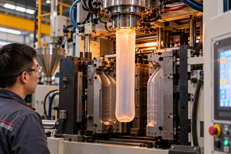
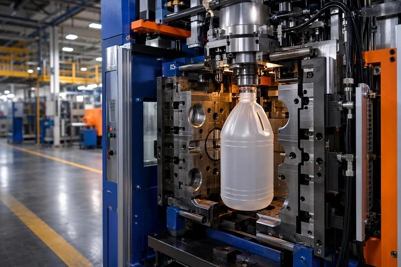
Blow injection molding is injection blow molding: a parison is injection molded around a blow tube or core rod in a hot injection mold, the core rod and parison are removed together and transferred to a blow mold, and the parison is then inflated to the cavity shape. It is one of three principal blow molding techniques, and the three differ only in how the parison is prepared — by extrusion, by injection, or by injection followed by stretching.
The terminology causes more confusion than the process does. “Blow injection molding” is not a fourth technique sitting alongside the other three; it is the same process as injection blow molding, with the words reversed. What matters for a specification is which of the three parison routes is being quoted, because that choice determines tooling architecture, achievable tolerances and cycle rate.
Two boundaries are worth stating at the outset. IBM is not the route to biaxially oriented PET beverage bottles — that is injection stretch blow molding, and the orientation it produces cannot be obtained by IBM. And IBM is not a substitute for solid-part injection molding: it makes hollow, one-piece articles, and a part that is essentially solid or open-section belongs in a conventional mold.
Injection Blow Molding vs. Extrusion Blow Molding
Extrusion blow molding forms the parison by extruding it downward through a die, closes the two mold halves around it — pinching the top closed and sealing a blow pin at the bottom — and inflates it. The cycle is continuous and fast, which is why extrusion blow molding is the standard route for mass-produced bottles, handleware, industrial containers and automotive ducting. The cost of that speed is a pinch-off seam, looser tolerances, and wall distribution that depends on parison control rather than on a molded preform.
IBM molds the parison on a core pin instead. Because the neck is formed in the injection cavity rather than blown, it holds injection-molding tolerances — roughly ±0.005 in (±0.13 mm) — while the blown body does not. There is also no pinch-off scrap to trim. The trade is production rate: IBM runs slower than extrusion blow molding, and it is limited to smaller parts and cannot produce integral handles.
The practical reading is that the trade-off is precision and repeatability against cycle speed. Neither process is universally superior; a 200-liter drum and a 30 ml pharmaceutical bottle are simply different problems.
Injection Blow Molding vs. Injection Stretch Blow Molding
Injection stretch blow molding begins the same way as IBM, with an injection-molded preform. The difference is what happens at the blow station: a stretch rod drives down the axis while pre-blow and then final blow air expand the preform, stretching it both axially and circumferentially. Typical ratios are 2–3× axially and 3.5–4.5× in the hoop direction, for a planar orientation of roughly 10–16×. That biaxial molecular orientation is what gives PET bottles their clarity, stiffness and gas barrier; an unoriented PET bottle of the same weight is hazy and creeps under carbonation pressure.
IBM does not impart this orientation. Where a part’s performance depends on oriented material properties — pressure retention, transparency, barrier — the two processes are not interchangeable, and IBM should not be offered as a substitute.
The Blow Injection Molding Process, Step by Step
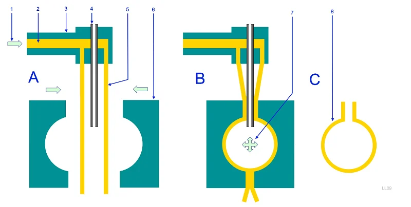
The IBM cycle is best understood as a chain in which each stage hands a specific condition to the next. The injection stage fixes the neck geometry and the material distribution; conditioning decides whether that distribution can inflate evenly; transfer and blowing convert it into the body shape; cooling locks the result in. A defect that appears at the end usually originates one or two stages earlier.
Preform Injection and Core Rod Conditioning
The preform is injected around a blow tube or core rod inside a hot injection mold. Because the neck is formed here rather than blown, this stage sets the closure thread, the sealing land and every tight dimension on the part — which is why tight-tolerance features should live at the neck and stay off the blown body. The injection stage also determines how much material sits where, and the blow stage can only redistribute what it inherits.
The preform’s temperature profile at transfer governs how it inflates. Too cool and the material resists stretching, thinning unevenly or failing to fill corners; too hot and it sags or sticks. Uniformity across the preform matters as much as the average temperature, because a temperature gradient becomes a wall-thickness gradient once air pressure is applied. In multi-station machines the core rods circulate in sets, which allows preform injection, blowing and ejection to run concurrently and gives the preform a defined interval to equalize before it reaches the blow station.
Transfer, Inflation, and Cooling
The core rod and preform are removed from the injection mold and indexed to the blow mold, where the mold halves close around the preform and air is introduced through the blow pin. Core rod alignment at this moment is critical: if the preform sits off-centre in the cavity, the blow-up ratio varies around the circumference and one side of the part runs thin.
Blow pressure and timing then set how faithfully the plastic reproduces the cavity. Inflation pressures differ substantially by route — roughly 25–150 psi (1.7–10 bar) for extrusion blow molding against 500–600 psi (35–40 bar) for PET stretch blow molding — and low pressure cannot force material into deep ribs or sharp detail, which is why rib and emboss depth is normally held to about half the wall thickness.
Cooling is where the final geometry is fixed. Cooling time and mold temperature control determine dimensional stability and residual stress, and uneven cooling shows up later as warpage or wall variation. Water channels within the mold assist cooling, and the cooling layout has to be balanced around the part rather than concentrated where it is convenient.
Ejection and Secondary Operations
After the cooling period the blow mold opens, the core rod rotates to the ejection position, and the finished article is stripped off. Where the process allows it, parts can be leak-tested before packing — a sensible in-line check for containers that will hold liquids.
IBM produces no pinch-off scrap, so deflashing is usually minimal compared with extrusion blow molding. Any trimming, drilling, labelling or assembly that remains is a secondary operation, and secondary operations add cost and variability; they should be designed out where the geometry permits rather than absorbed into the routing.
Materials Used in Blow Injection Molding
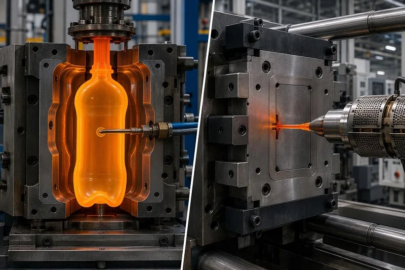
The most widely used blow molding materials are low-density polyethylene, high-density polyethylene, polypropylene, PVC and PET. Blow molding produces disposable containers of various sizes and shapes, drums, recyclable bottles, automotive fuel tanks, storage tanks, globe light fixtures, toys, tubs and small boats.
Material choice in IBM is constrained by a specific requirement: the parison must hold together during transfer and inflate uniformly once it reaches the blow mold. That is a different constraint from extrusion blow molding, where the parison must support its own weight as it hangs from the die — which is why melt strength dominates EBM grade selection, and why an injection molding-grade HDPE with a melt flow index of 5–15 g/10 min cannot produce a stable parison in EBM. Because the IBM parison is injection molded, the process accommodates a wider range of polymers than extrusion blow molding does. That is a relative statement, not a licence to assume any engineering resin is routinely blow molded.
Commodity and Engineering Resins in Blow Molding
The common families sort by application logic rather than by technical ranking. Polyolefins — LDPE and HDPE — carry containers and tanks, where toughness, chemical resistance and cost drive the choice. Polypropylene covers containers and closures that need higher temperature resistance and stiffness. PVC appears where clarity and chemical resistance matter in certain containers. PET is the beverage and pressure-capable bottle material, but it reaches those properties through injection stretch blow molding, not IBM.
Process and material must be matched before anything else is evaluated. Automotive fuel tanks illustrate how far the matching can go: modern tanks use a multilayer HDPE/polyamide coextrusion, typically six layers including a 0.2–0.4 mm PA6 barrier layer, because neat HDPE alone does not meet hydrocarbon permeation limits. That structure is an extrusion blow molding achievement.
Where PEEK Fits — and Where It Does Not
PEEK is a semi-crystalline, high-performance polymer with a modulus similar to bone, excellent chemical resistance to organics, acids and bases, compatibility with steam, EtO, gamma and e-beam sterilization, and high mechanical strength retained above 250 °C. Those properties are why it appears in medical and demanding industrial applications.
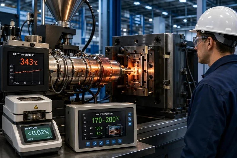
They are also why it is demanding to process. PEEK is hygroscopic and must be dried to below 0.02% moisture before melting; incomplete drying produces surface streaks, splay and severe bubbling or porosity. Typical injection molding conditions run at a melt temperature of 370–385 °C (698–725 °F) and a mold temperature of 175–205 °C (350–400 °F), with barrel zones up to about 400 °C. Mold temperature is not a formality: below roughly 170 °C the melt quench-cools into an amorphous state instead of the semi-crystalline structure that delivers PEEK’s properties. PEEK also shrinks more than amorphous resins, which is why generous gates and careful packing matter.
The honest position is that this published guidance describes blow injection molding, not PEEK blow injection molding. PEEK should not be treated as a standard blow molding resin on the strength of its injection molding data. Whether a specific PEEK grade can be blown into a given hollow geometry is a question for a feasibility trial with a molder who has the hot tooling and drying discipline the material requires — and the answer may be no. Where a hollow PEEK part is required, alternatives worth evaluating include machining the form from PEEK stock and molding sub-assemblies that are subsequently joined. These are options to assess against the part’s requirements, not established equivalents to blow molding.
Applications of Blow Spuitgieten

IBM’s precision advantage pays off in a fairly narrow band: small hollow parts where the neck finish carries the function, and where wall distribution has to be consistent enough that the part’s weight and strength are predictable. Outside that band, other routes usually win.
Packaging and Pharmaceutical Containers
Small pharmaceutical and personal-care bottles are the classic IBM application. The reason is structural: in IBM the neck is injection molded rather than blown, so it holds injection-molding tolerances of about ±0.005 in (±0.13 mm) while the blown body does not. Closure fit, thread engagement, tamper-evident features and seal integrity all depend on that neck accuracy, and a neck that varies from part to part produces cap torque problems and leakers on the filling line.
Consistent wall sections matter for a second reason: fill-line performance and weight consistency. A container whose walls vary around the circumference holds a slightly different volume, weighs differently, and behaves differently under top-load. Standard finishes such as the SP-400 and SP-410 series let a project specify a stock closure rather than a custom one, which is worth doing when the design allows it.
Industrial and Automotive Hollow Parts
The broader hollow-part territory — drums, jerry cans, fuel tanks, storage tanks, ducts and air intakes — is overwhelmingly served by extrusion blow molding, not IBM. These parts are large, often need integral handles or thick industrial walls of 0.080–0.250 in (2–6 mm), and are produced in volumes where extrusion’s cycle speed dominates. IBM is limited to small parts and cannot produce integral handles, so it is the wrong tool for this family regardless of how precisely the neck could be molded.
Knowing when IBM is the wrong choice is as useful as knowing when it fits. Very large parts are out. High-volume commodity containers are out on cycle economics. Anything that depends on biaxial orientation — carbonated beverage bottles above all — is out, because IBM does not orient the material. Within the remaining space, IBM competes on neck precision and the absence of pinch-off scrap.
Blow Injection Molding Compared with Other Processes
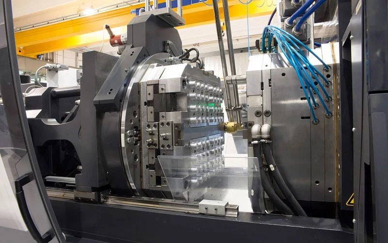
Six routes are worth putting side by side for a hollow part: injection blow molding, extrusion blow molding, injection stretch blow molding, conventional injection molding, CNC machining and additive manufacturing. The comparison criteria are hollow geometry capability, dimensional precision, tooling investment, cycle rate, material range and surface finish. No single route leads on all six, and the table below is a decision aid rather than a ranking.
Comparison Criteria and How to Read Them
Hollow geometry capability asks whether the route can produce a closed, one-piece shell at all, and with what features — integral handles, restricted openings, internal threads. Dimensional precision has to be tied to a specific feature: a blow molded part’s neck and its body sit at very different tolerances, and quoting a single figure for the whole part misleads.
Tooling investment and cycle rate trade against each other. A route with cheap tooling often has a slow cycle or a high per-part labour content, and a route with fast cycles often carries a large fixed tool bill. Precision claims must be tied to a specific part and material rather than to a process label, because the same process can hold tight tolerances on one geometry and loose ones on another. Material range asks which polymers the route can actually process — not which polymers exist. Surface finish depends heavily on mold surface and on where the parting line falls.
Comparison Table: Hollow-Part Routes
The table keeps entries qualitative and part-specific. Where a route is marked limited, the limitation is a known process characteristic rather than a judgement about any supplier.
| Route | Hollow geometry | Dimensionele presisie | Gereedskapbelegging | Siklus koers | Materiaal reeks | Oppervlak |
| Injection blow molding (IBM) | One-piece hollow, small parts; no integral handles | High at injection-molded neck (~±0.005 in / ±0.13 mm); moderate on blown body | Injection cavity plus blow mold — more involved than a single injection mold | Moderate; slower than extrusion | Wider than extrusion because parison is molded | Good; no pinch-off seam |
| Extrusion blow molding (EBM) | One-piece hollow, large parts; handles and thick walls | Moderate; pinch seam and looser tolerances | Moderate; simpler than IBM for large parts | Hoogte | Requires melt strength; polyolefins dominate | Gloss to matte or grained; pinch-off seam always visible |
| Injection stretch blow molding (ISBM) | One-piece hollow, beverage and pressure containers | High at neck; body oriented and dimensionally stable | Injection preform mold plus blow mold | Hoogte | Essentially PET for oriented performance | Clear, high gloss |
| Konvensionele spuitgietwerk | Solid and open-section parts; hollow only via cores, gas assist or joined shells | High, feature-dependent | High; core, side-action or unscrewing mechanisms add cost | Hoogte | Breë | Excellent, mold-dependent |
| CNC bewerking | Hollow forms cut from solid stock or from two halves | High, feature-dependent | Very low to none | Low per part; suited to small quantities | Broad, including PEEK stock shapes | Good; tool marks controllable |
| Addisionele vervaardiging | Complex internal geometry; often used for validation | Moderate; process- and orientation-dependent | Geen | Low per part; suited to prototypes and low quantities | Narrower than machining | Layer-dependent |
Ratings are indicative and part-specific. Actual capability depends on material, size, geometry, finish and inspection requirements.
When Conventional Injection Molding Beats Blow Molding
Solid and open-section parts belong in conventional injection molding. Hollow shapes can sometimes be produced there too — by inserting and releasing an internal core with practical draft, by using a collapsible, unscrewing or side-action core for restricted openings and internal threads, by a removable or sacrificial core, by gas assist, or by molding two shells and joining them.
Each of those options is a trade, not a free upgrade. Lightweighting by removing material can reduce mass, but it can also reduce bending stiffness, alter impact response, increase sensitivity to buckling or weld lines, and make shrinkage, cooling and warpage harder to control. A thinner shell may save mass and lose stiffness in bending or local compression; a taller or deeper section can sometimes restore section stiffness without adding much material. Hollow-for-hollow’s-sake is not automatically an improvement, and a generic lightweighting percentage is not a design approval.
When Machining or Additive Manufacturing Fits Better
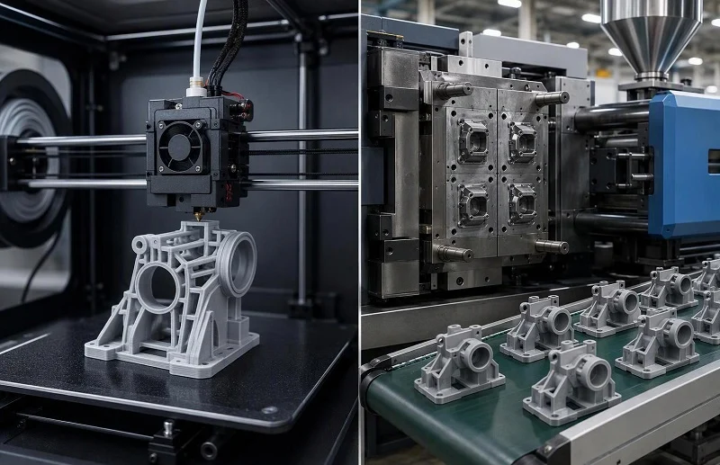
CNC machining and additive manufacturing are the practical routes for prototypes, low quantities, and geometries that do not justify blow molding tooling. Machining holds tight tolerances on solid stock and can produce a hollow form by cutting it from two halves or from a thick-walled blank; additive manufacturing reaches internal geometry that would be difficult to mold at all.
The choice between them depends on quantity, material and tolerance rather than on a general hierarchy. A common and sensible sequence is to use CNC machining to verify structure and assembly first, then evaluate a production process such as injection molding or blow molding once the design is stable. Tight tolerances should be applied only to dimensions that affect function, fit or inspection, with datums, inspection method and acceptance criteria defined — unnecessary tight tolerances add machining, inspection and rework risk without adding value.
Low Volume Injection Molding, Prototyping, and Tooling Economics

Hollow parts can be prototyped and produced at low volume, but the economics work differently from solid-part injection molding, and the difference is worth understanding before a budget is set.
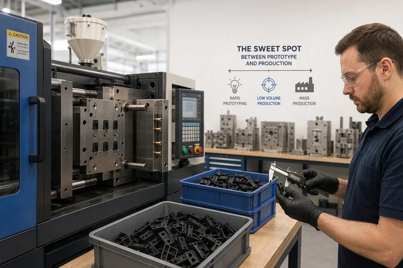
Blow injection molding requires two tool sets: an injection cavity that forms the preform on the core rod, and a blow mold that forms the final body. The tooling set is therefore more involved than a single-cavity injection mold, and that fixed investment has to be spread over the production quantity. Low volume injection molding is realistic where the part design is stable and the quantity justifies the tooling; it is not realistic where the design is still moving, because a tool change at low volume wipes out the amortization entirely.
The usual answer is to separate validation from production. Prototyping routes such as machining or additive manufacturing confirm geometry, wall sections and assembly interfaces before blow molding tooling is committed. Bridge tooling and family tools are options worth discussing with a manufacturer where quantities sit between prototype and volume — but they are options to evaluate against the specific part, not standard inclusions.
How Tooling Cost Scales with Quantity
The arithmetic is simple and worth writing out. If a fixed tooling cost T is spread over a quantity Q, the tooling contribution to each part is T ÷ Q. The per-part cost is then that contribution plus the variable cost of material, machine time and finishing.
Take a hypothetical tooling cost of $60,000. At 500 parts, the tooling contribution is $120 per part. At 5,000 parts it is $12. At 50,000 parts it is $1.20. The variable cost per part does not change much across those quantities; what changes is how much fixed cost each unit carries. That is why low volume production carries a cost premium per part, and why the premium shrinks as volume rises.
The practical implication is that low volume injection molding should be judged on total project cost rather than on unit price alone. A higher unit price at 500 pieces may still be the right decision if it validates a design that would otherwise be tooled twice.
Validating a Hollow Part Before Cutting Tooling
A prototype-first approach is about answering specific questions cheaply. Before tooling commitment, a prototype can confirm wall sections and the resulting weight, neck and closure geometry, the material’s behaviour in the intended section thicknesses, and whether the assembly interfaces line up with mating parts.
It cannot confirm everything. A machined or printed prototype does not reproduce the blow molding process window, the wall distribution that inflation produces, or the residual stress and shrinkage behaviour of the production tool. Those questions are answered by a documented mold trial, not by a prototype. The point of the prototype is to make sure the mold trial is testing process questions rather than design questions.
Design Considerations and Validation Before Production Tooling
Most of the decisions that determine whether a hollow part succeeds are made before the tool is cut. The checklist below covers the ones that most often come back as change requests later.
Wall thickness uniformity is the first. Large thickness variations lead to weak areas, excessive material use and inconsistent part performance, and because wall thickness in blow molding is an outcome of shot weight and local stretch rather than something specified directly, the design should be evaluated at its thinnest predicted section. Blow-up ratio matters here: 2:1 to 2.5:1 is the recommended range, with 3:1 as a practical limit, beyond which corners thin out and go brittle. Internal radii of 2–3× wall are recommended, with 1× wall as a limit, because corners stretch most and end up thinnest.
Draft and ejection come next. Smooth surfaces need 0.5–1° per side, with 0.25° as a limit; textured surfaces want 1–1.5° because texture depth adds required draft. The part shrinks away from the cavity as it cools, which is why blow molds need less draft than injection molds — but the injection-molded neck still follows injection molding rules.
Where the injection stage applies, gate and venting decisions follow PEEK-style discipline in principle: gate into the thickest section where practical so packing pressure can be maintained through solidification, and provide generous venting at flow-front termination points and weld lines. The neck and closure interface should be settled early, ideally against a standard finish so a stock closure can be used. Finally, decide which quality parameters will be inspected and how: dimensional accuracy, surface finish, mechanical strength, seal integrity and weight consistency.
Wall Thickness, Draft, and Ejection
Wall uniformity governs both strength and weight. A part that is thick on one side and thin on the other is heavier than it needs to be and weaker where it is thinnest, and the thin section is usually the one that fails first under drop or top-load. Consumer container walls typically land at 0.012–0.040 in (0.3–1.0 mm), while industrial extrusion blow molded tanks and ducts run 0.080–0.250 in (2–6 mm).
Draft and ejection design prevent deformation during removal. Because the part is still warm when it comes off the core rod, ejector pin sizing and placement have to be verified to avoid distorting it. Thin or unsupported features are the usual casualties.
Quality Parameters and Common Defects
Quality control in blow molding rests on six parameters: wall thickness uniformity, dimensional accuracy, surface finish, mechanical strength, seal integrity and weight consistency. Each has a control method — thickness gauges and sensors, callipers, micrometers and CMMs, visual inspection and gloss meters, drop and compression and pressure testing, vacuum and air pressure and bubble leak tests, and regular weighing on precision scales.
The common defects and their typical causes are worth keeping as a reference during troubleshooting. They are typical associations rather than certainties, and more than one cause can produce the same symptom.
| defek | Beskrywing | Tipiese oorsake |
| flits | Excess material at parting lines | High melt temperature, excessive clamping force, worn parting line |
| Dun mure | Uneven or weak wall sections | Improper parison control, mold alignment issues |
| Brandmerke | Discoloration or scorched areas | Overheating, poor venting |
| Bubbles | Air trapped inside walls | Moisture in material, poor molding parameters |
| buiging | Distorted shape | Uneven cooling, incorrect mold temperature |
Most of these trace back to process parameters, mold alignment, moisture or cooling balance rather than to the process concept. That is the reason validation should produce a documented process window — a range of temperatures, pressures and times within which the part is known to be good — rather than a single successful trial. A single good shot proves the process can work once; a window proves it can work repeatedly.
Choose NOBLE for Your Blow Injection Molding Project

NOBLE is a Sino-British joint venture, awarded by the government as a “National High-tech Enterprise”, and a precision manufacturer in China supporting customers on blow injection molding projects. Our service capability and processing expertise are set up to help you move efficiently from prototype to volume production, so a blow injection molding project does not stall between the first article and the batch order.
Our certifications are stated plainly: NOBLE is certified to ISO 9001:2015 and ISO 13485:2016. The second matters particularly for medical device work, where process documentation and traceability are part of the deliverable rather than an afterthought.
What we offer is a full service from design through assembly — not production alone. That covers the path from prototyping to batch manufacturing: design input and manufacturability review, prototyping in suitable materials and surface finishes, tooling, production, inspection, and assembly. For a blow injection molding project, that continuity is useful precisely because the material is unforgiving — drying to below 0.02% moisture, melt temperatures around 370–385 °C, mold temperatures around 175–205 °C and the semi-crystalline structure that depends on holding them. Those are process disciplines, and they belong with the same team from the first trial to the production run.
If you are evaluating a blow injection molding project, the practical next step is to submit an RFQ with the information needed for a quote: the controlled 3D model and drawing revision, material grade and any filler content, target quantities, critical dimensions and tolerances, surface finish requirements, and the application conditions the part will see. With those inputs, we can frame the manufacturing discussion around your part rather than around a generic capability list.
FAQs about Blow Injection Molding
Is blow injection molding the same as injection blow molding?
Yes. “Blow injection molding” and “injection blow molding” (IBM) describe the same process: a parison is injection molded onto a core rod, transferred to a blow mold, and inflated to the cavity shape. It is one of the three principal blow molding techniques, alongside extrusion blow molding and injection stretch blow molding, and it is not a separate fourth process.
Is low volume injection molding realistic for hollow parts?
It can be, where the design is stable and the quantity justifies the tooling. Blow injection molding needs both an injection cavity and a blow mold, so the fixed tooling investment is larger than for a single injection mold, and the per-part tooling contribution is that investment divided by the quantity. At low volume the contribution is high; at high volume it becomes small. Prototyping by machining or additive manufacturing before tooling commitment is the usual way to avoid paying for tooling twice.
What should be validated before committing to production tooling?
Wall thickness uniformity at the thinnest predicted section, blow-up ratio, internal radii, draft for the intended surface texture, neck and closure interface, gate and venting where the injection stage applies, and the inspection plan covering dimensional accuracy, surface finish, mechanical strength, seal integrity and weight consistency. Validation should end with a documented process window rather than a single successful trial.
How do I choose between blow molding and other processes?
Weigh the six criteria — hollow geometry capability, dimensional precision, tooling investment, cycle rate, material range and surface finish — against your own priorities, and tie precision claims to a specific feature and material. Small parts with functional neck finishes favour injection blow molding; large industrial and automotive hollow parts favour extrusion blow molding; pressure-capable PET bottles require injection stretch blow molding; solid and open-section parts belong in conventional injection molding; and prototypes and low quantities are usually best served by CNC machining or additive manufacturing. The answer depends on geometry, material, quantity and tolerance rather than on a general hierarchy.