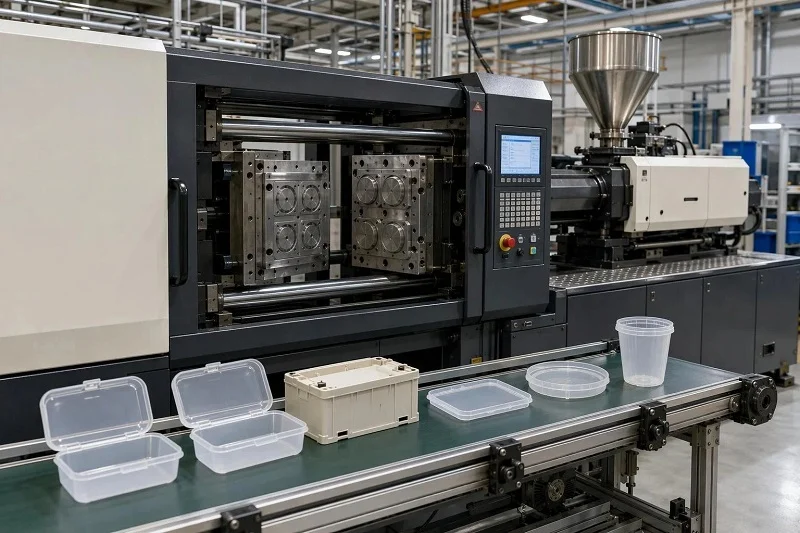
PP injection molding converts polypropylene pellets into finished parts by melting the resin, forcing it under pressure into a closed mold, cooling the plastic, and ejecting the solid result. Few thermoplastics combine such low density, broad chemical resistance, long flex life and low cost per part, which is why polypropylene ranks as the second most produced plastic worldwide and anchors so many high-volume programs.
That combination is also why the material rewards informed decisions and punishes assumptions. A grade chosen for stiffness may fail an impact test; a tool cut to an average shrinkage figure may drift out of tolerance once packing pressure changes; a living hinge gated without uninterrupted flow across the web may tear in the field. This guide works through those decisions in the order a project meets them: what PP injection molding is and how the resin behaves, the molding cycle step by step, grade selection, shrinkage and tolerances, design rules, proven applications, comparisons with thermoforming, blow molding, machining and additive manufacturing, defect troubleshooting, and what to expect from a manufacturing partner. Each section stands on its own, so you can move directly to the decision in front of you.
What Is PP Injection Molding and Why It Matters
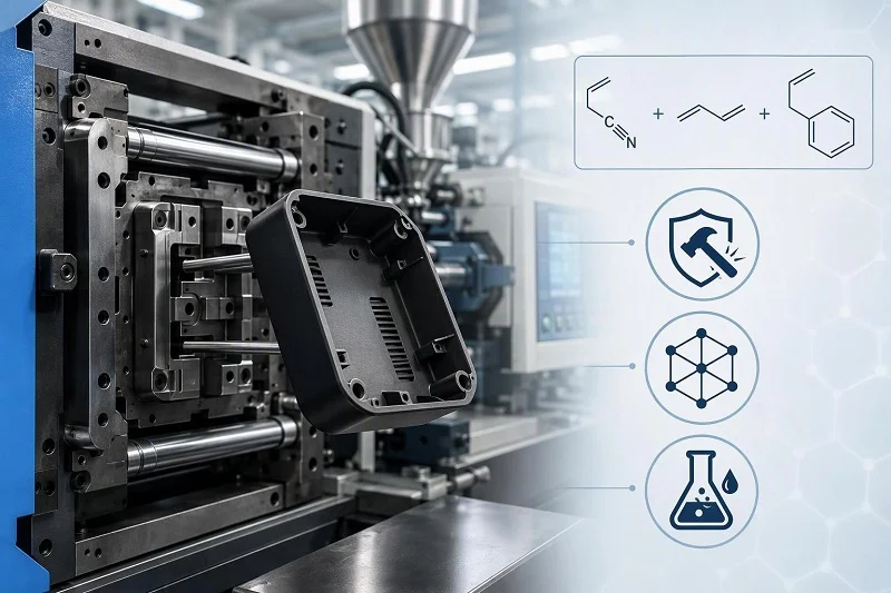
PP injection molding is the high-volume conversion of polypropylene into finished parts through melting, pressurized filling of a closed steel or aluminum mold, cooling and ejection. The material’s property set explains the process choice: density near 0.90 g/cm³, so parts float; a semi-crystalline structure that sets up quickly in the mold; a melting point around 160 °C with continuous service near 100 °C; excellent acid and base resistance; fatigue resistance strong enough for integral hinges; and moisture absorption low enough that pre-drying is usually unnecessary.
The trade-offs are equally real. Unstabilized PP degrades under sustained UV exposure, its low surface energy complicates bonding and printing, its stiffness sits below engineering plastics such as PET or nylon, and its mold shrinkage is large enough to make dimensional planning a design task rather than an afterthought.
Key Properties That Shape Processing Decisions
Each property maps to a processing consequence. Semi-crystalline solidification produces a sharp viscosity rise on cooling, so the melt sets fast and cycle times can be short. Low thermal conductivity makes cooling the usual cycle-time limiter. High responsiveness to injection speed and pressure permits fast fills and thin walls. The wide shrinkage window, roughly 1.0–2.5% linear (0.008–0.025 in/in), is the root cause of the dimensional and warpage topics later in this guide.
| Property | Representative value |
| Density | 0.90 g/cm³ |
| Tensile strength | 30–40 MPa |
| Elongation at break | 100–600% |
| Young’s modulus | ~1.5 GPa |
| Heat deflection temperature | ~100 °C |
| Dielectric constant | ~2.2 |
| Recycling code | 5 |
These are representative figures for the family, not specifications; the resin datasheet for your grade governs.
Homopolymer vs. Copolymer vs. Filled and Specialty Grades
Grade families divide along the balance of stiffness, toughness and clarity. Homopolymer is the stiffest and most heat resistant, and it makes the strongest living hinges. Impact copolymer adds a rubbery dispersed phase for toughness at low temperature, which suits automotive and cold-chain parts. Random copolymer trades some stiffness for clarity and a lower sealing temperature, favoring thin-wall packaging. Glass-filled grades raise stiffness and dimensional stability; flame-retardant, medical and nucleated or clarified grades address specific compliance, sterilization or appearance requirements. The detailed selection logic appears in the grade-selection section that follows the process walkthrough.
The PP Injection Molding Process, Step by Step
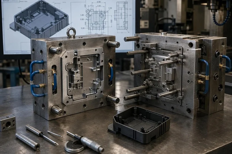
The cycle runs from resin handling to inspection, and PP needs no special equipment: it molds on standard single-stage screw machines without alteration, which is part of its cost advantage.
Material Preparation and Drying
Pre-drying is generally unnecessary under normal conditions, though filled grades may require it. Regrind from sprues, runners and rejected parts can be re-blended at 30–40% on a constant add-back basis; higher levels reduce impact and flow because too much material carries three or more heat histories. Coloring routes—pre-colored resin, dry color, solid concentrate or liquid color—trade dispersion control against equipment cleanliness.
Melting, Plasticating and Melt Temperature
The reciprocating screw melts and meters the resin. Cylinder temperatures typically run 400–570 °F (about 205–300 °C), with most jobs in the 400–525 °F band; set the melt 25–50 °F above the minimum needed to fill, and keep the feed section 30–50 °F cooler than the nozzle. Starting conditions by melt flow rate band:
| Nominal MFR (g/10 min) | 2–10 | 10–20 | 35–50 |
| Melt temperature | 475 ± 5 °F | 465 ± 5 °F | 455 ± 5 °F |
| Mold temperature | 50–150 °F | 50–150 °F | 50–150 °F |
Too hot a melt invites flash, burning, sink, warpage and voids; too cold a melt produces flow marks, weld lines, short shots and molded-in stress.
Injection, Packing and Hold Pressure
First-stage pressure usually falls between 800 and 1,500 psi, sized to fill roughly 99% of the part. Injection time matters far more for shrinkage than for warpage. Packing and hold then control sink, voids and final dimensions: too much pressure causes flash, burning, sticking and warp, while too little leaves sink and undersized parts. Back pressure of 50–100 psi gauge is sufficient, and screw speed is the lever for recovery time.
Cooling, Ejection and Cycle Time
Cooling dominates cycle time because PP conducts heat poorly. Cool the part to about 130 °F before ejection; shortening hold time increases warpage, sink and shrinkage. Cool uniformly unless deliberate differential cooling is needed to counter warpage. Ejection needs balanced knockout, large pins, air relief on long cores and adequate draft.
Inspection and Quality Control
Inspect a first-article dimensional layout against the drawing, then critical-to-function dimensions, visual standards for flow marks and sink, and weld-line integrity in load-bearing areas; living hinges warrant functional cycling tests. Because PP shrinkage varies, validate dimensions after the part has stabilized, and run SPC on key dimensions to catch drift before scrap.
Choosing the Right PP Grade for Your Part
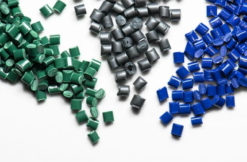
Grade selection is a decision procedure, not a catalog lookup. Work through the questions a designer actually faces: what stiffness-to-toughness balance, what service temperature, what chemical environment, which sterilization method, what appearance, and how much flow length against wall thickness. Melt flow rate is the primary processing selector. Choose the lowest flow that fills the part within reasonable melt temperature and pressure limits, because lower-flow resins have higher molecular weight and generally better toughness. Note that standard melt flow data is measured at low shear and can mislead when comparing broad and narrow molecular weight distributions.
Matching Melt Flow Rate to Wall Thickness and Flow Length
Thin walls and long flow paths push toward higher melt flow; thick sections and toughness-critical parts favor lower flow. Too-high flow shows up as flash, hard-to-pack parts, bubbles and brittleness; too-low flow as short shots, seizing or sticking from over-packing, and melt temperatures that lengthen cycles or degrade the resin. Molding area diagrams map the usable pressure and temperature window for a given grade.
Additives: Nucleators, Antistats, UV Stabilizers and Clarifiers
Nucleating agents create many small crystals, improving thin-section clarity, flexural modulus, heat deflection temperature, stain resistance and barrier properties while shortening cycles; the costs are core shrinkage, sticking if ejection is slow, and reduced knit-line strength. Antistats bloom to the surface to dissipate static and act as slip and internal mold release, but they block printing and can leave a white bloom on dark parts after storage. UV stabilizers or high carbon black loading extend outdoor life without making PP a true outdoor material. Clarifiers improve transparency in random copolymers.
Medical, Food-Contact and Flame-Retardant Grades
Compliance drives this tier. Food-contact grades and grades suitable for medical devices carry application-specific listings. On sterilization, PP and PP copolymers rate “Good” for autoclave and ethylene oxide, but only “Fair” for gamma and electron-beam unless radiation-stabilized grades are used. Flame-retardant PP grades exist but change mechanical and processing behavior. Confirm biocompatibility and regulatory listings with the resin supplier for the actual application.
Shrinkage, Tolerances and Dimensional Control in PP Injection Molding
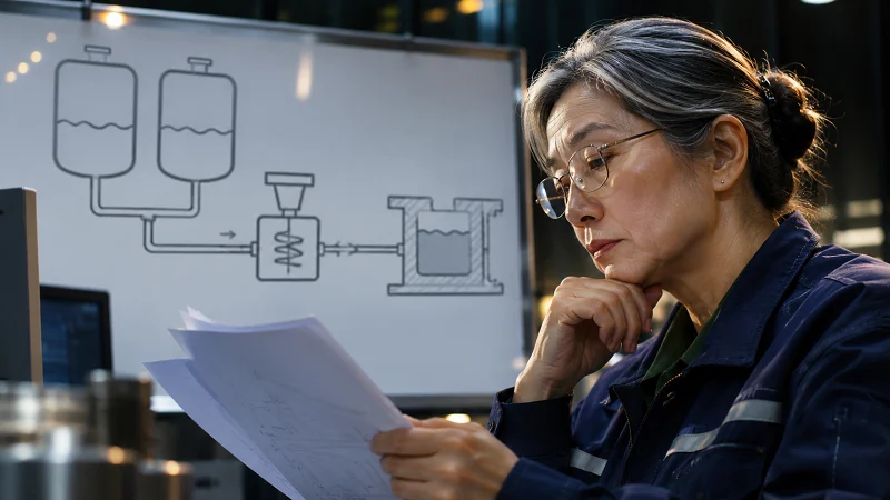
Linear mold shrinkage for PP runs roughly 0.008–0.025 in/in, or about 1.0–2.5%, depending on resin, molding conditions, part design, wall thickness and flow direction. The average shrinkage line is a design starting point, not a guarantee. Flow-direction and cross-flow shrinkage differ, and that difference is the source of differential shrinkage and warpage. Set tolerances from the demonstrated capability of the specific grade and tool rather than from a generic table. Filled grades shrink less and more isotropically.
Isotropic vs. Anisotropic Shrinkage
Semi-crystalline PP shrinks differently along and across the flow direction because molecular orientation follows the fill pattern. Gate location therefore sets orientation, which makes gate placement a dimensional tool as much as a filling tool. Center gating a rectangular part, for example, warps opposite corners in opposite directions; end gating or multiple gates along one edge give more unidirectional flow and more predictable shrinkage. This is why the design guidance on uniform wall and gradual transitions matters twice: it controls stress and it controls the shrinkage pattern.
Setting Realistic Tolerances and Planning Tool Compensation
The practical workflow starts with resin supplier shrinkage data, applies the average for the wall thickness, builds tool steel with compensation, then runs a tool trial and adjusts. Packing pressure and hold time move dimensions—more pack produces larger parts—so dimensional control is a process-control problem as well as a tool problem. Avoid specifying tolerances tighter than the process can hold across the full shrinkage window without a capability study behind them.
Design Rules for PP Injection Molded Parts
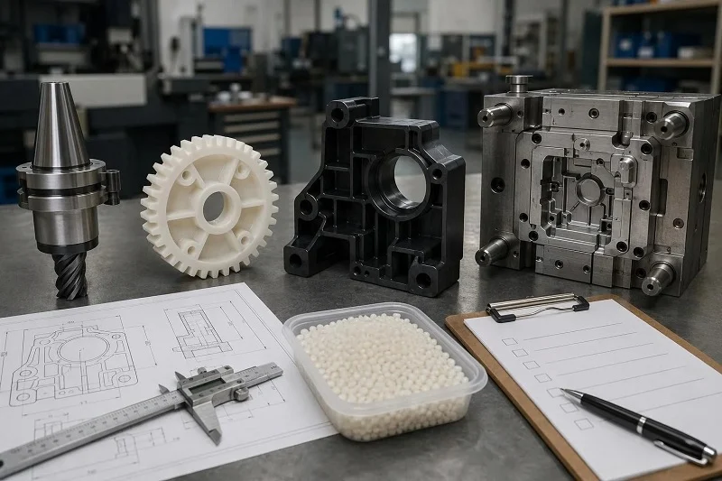
PP’s flexibility enables features that rigid plastics cannot easily achieve—snap fits, living hinges and strip undercuts—but its shrinkage makes uniform wall and gradual transitions more important than in amorphous resins. Check each feature below against the model before releasing the tool.
Wall Thickness and Transitions
Keep walls uniform and avoid abrupt thickness changes, which cause part weakness and distortion through corner notch effects and induced shrinkage stresses. Radius or taper any transition to minimize stress concentration and warpage. At rib-surface intersections and changes in surface direction, use radii of at least 1/32 in for walls up to 0.090 in and 1/16 in for walls from 0.090 to 0.180 in.
Ribs, Bosses and Sink Control
Keep the rib base no more than 50% of the attached wall and the rib height no more than about 1.5 times that wall, with a base radius near W/8 and 1.5–2° draft. Bosses need heavier walls for their function, so sink is usually managed by surface texture or by designing in a mask rather than by thinning the boss. Highly filled grades shrink less and show correspondingly less sink.
Draft Angles and Surface Finish
Unfilled homopolymer and copolymer parts on smooth surfaces need a minimum of 1° draft per side to prevent seizing as shrinkage grips the steel. Textured surfaces require 2–5° depending on texture depth, and filled resins need 4–10°. Those same filled grades, with low shrinkage and high stiffness, cannot be stripped from anything but very minor undercuts.
Undercuts, Snap Fits and Living Hinges
Unfilled PP homo- and copolymers can be stripped from undercuts provided the feature is not trapped by mold metal, uses a tapered or radiused form, and stays within roughly 0.035–0.040 in per inch of diameter. Living hinges are PP’s signature feature: land length 0.06–0.90 in, hinge thickness 0.008–0.20 in depending on how easily the lid should close, clearance about 0.010 in, and an offset radius of at least 0.030 in. Gate for uninterrupted flow across the web and run a separate mold-temperature channel parallel to the hinge, often held at 160–180 °F. Unfilled resins give stronger, better-looking hinges.
Gate and Runner Considerations That Affect Design
Feed from thick to thin, size the gate at no less than 50% of maximum wall thickness with a 0.030 in minimum, and keep gate land under 0.040 in to limit pressure loss. Runners should be at least 0.250 in equivalent diameter and never smaller than the heaviest wall; sprue taper runs 3–5° with length kept near 3 in, and vents about 1 mil deep for the first 0.005–0.010 in before flaring to 5 mils. Plan clamp force at roughly 2 tons/in² of projected area, rising to 4–6 tons/in² for integrally hinged parts.
Where PP Injection Molding Is Used and Why
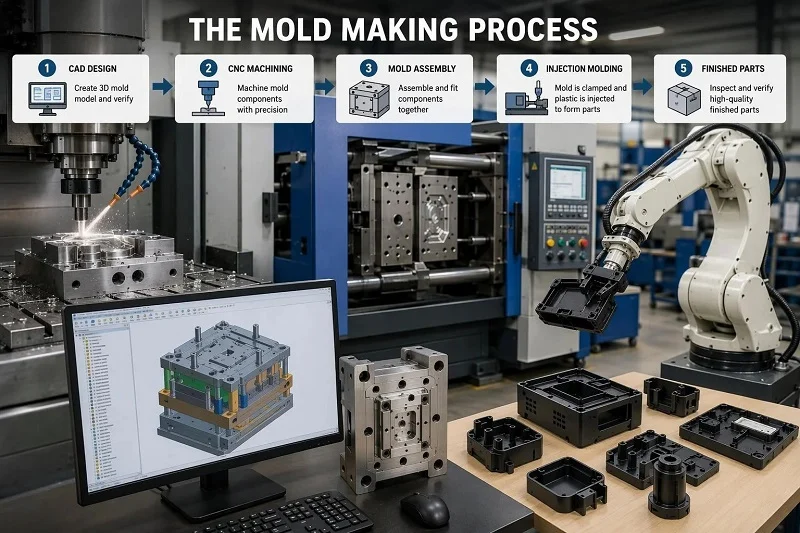
PP injection molding appears wherever low weight, chemical resistance and toughness matter more than stiffness. The sectors below are worth benchmarking against your own part: in each, a specific PP property, not general availability, explains why the material was chosen.
Packaging, Containers and Closures
Food containers, caps and closures, thin-wall tubs and hot-fill or microwave containers all lean on PP’s moisture barrier, heat resistance and food-contact grades. Antistat grades act as slip agents in closures, allowing a tighter fit at the same torque, while nucleation improves thin-section clarity and barrier performance.
Automotive Components
Bumpers, interior trim, door panels, dashboard components, battery cases and engine covers reflect PP’s lightweight, impact balance and ease of molding. Exterior trim exposed to sunlight needs UV-stabilized grades, since unstabilized PP degrades under strong direct exposure.
Medical Devices and Healthcare
Syringes, IV components, medical packaging, labware and disposable devices depend on grade-specific biocompatibility and sterilizability. PP and PP copolymers rate “Good” for autoclave and ethylene oxide, but only “Fair” for gamma and electron beam unless radiation-stabilized grades are specified.
Consumer Goods, Electrical and Industrial Parts
Storage containers, housewares, toys, garden furniture and appliance parts use PP for durability and chemical resistance. Electrical and industrial applications add pipes, fittings, tanks, chemical containers, filters and corrosion-resistant components, supported by volume resistivity around 10¹⁷ Ω·cm and a dielectric constant near 2.2.
PP Injection Molding vs. Other Manufacturing Processes
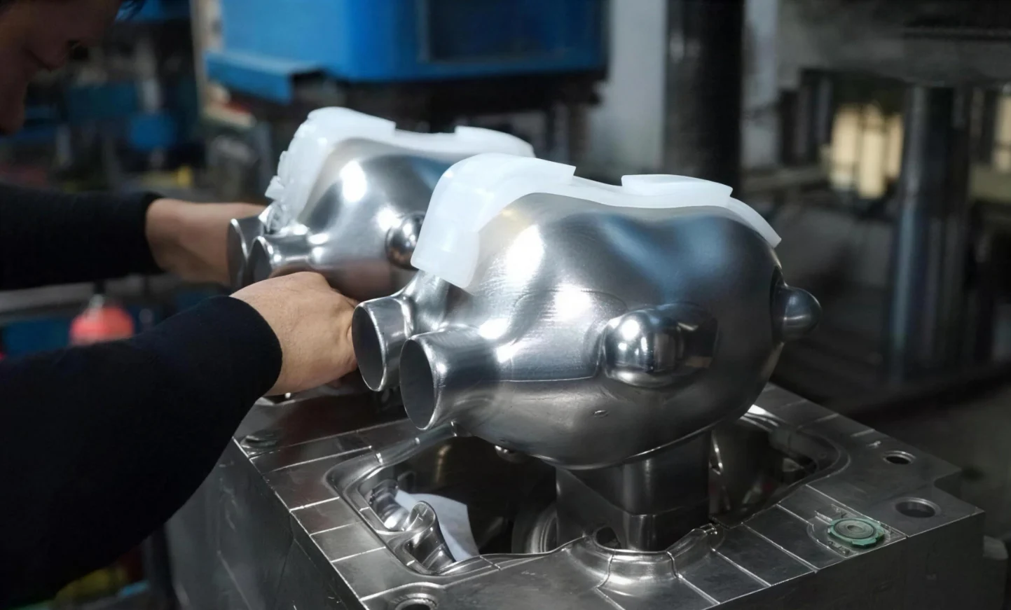
PP injection molding is not automatically the right answer. Volume, geometry and tolerance decide the process, and the comparison below shows where each alternative earns its place.
PP Injection Molding vs. Thermoforming
Thermoforming is economical at low-to-moderate volumes for large, thin-walled, simple parts such as food containers, but PP’s forming window is narrow: the sheet begins to bubble only 15–20 °F above the temperature at which it becomes formable, so forming must sit above the ~300 °F softening point and below the ~333 °F melt point, with preheating needed because of poor heat conductivity. Injection molding wins when geometry complexity, integrated features, tight tolerance or volume justify tooling.
PP Injection Molding vs. Blow Molding
Blow molding suits hollow, single-piece containers and bottles, where a parison is inflated against a mold cavity. Injection molding suits solid, feature-rich parts and multi-part assemblies. PP works in both, so the decision turns on geometry and volume rather than material availability, and injection molding can supply the closures and fitments a blow-molded body needs.
PP Injection Molding vs. CNC Machining
Machining is tooling-free and suits prototypes, low volumes and large or simple geometries; PP machines well on standard equipment with high speed, fine feed and sharp tools, and sawing needs tooth clearance such as 8 teeth per inch to avoid friction melting. Injection molding wins on per-part cost and repeatability at volume, and on features like living hinges and thin ribs that are impractical to machine.
PP Injection Molding vs. 3D Printing
Additive processes eliminate tooling and speed design iteration, and PP can be processed additively in some systems. Production parts, however, generally need the mechanical performance, surface finish and unit economics of molded PP. Treat printing as a prototyping bridge and injection molding as the production destination, committing to tooling when design freeze is credible.
Troubleshooting Common PP Injection Molding Defects
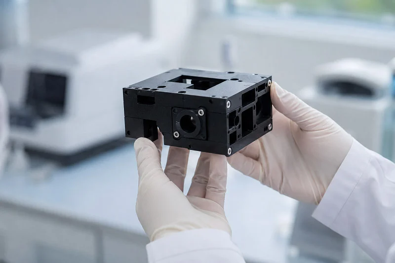
Most PP injection molding defects trace back to one of three levers: cooling balance, packing pressure and flow-front management. The entries below pair each symptom with its likely causes and the specific process or tool change that addresses it.
Warpage
Warpage usually signals insufficient cooling or unbalanced stress. Increase cycle time, relocate gates toward end gating, redesign to minimize wall variation, eliminate hot spots so both mold halves run at similar temperatures, and mold at higher temperatures with lower pressures and moderate fill rates.
Sink Marks
Sink comes from insufficient packing or heavy sections that stay molten after the gate freezes. Increase pack pressure and time, reduce cylinder temperature while raising fill pressure, slow the fill rate, gate into heavy sections, and thin ribs and bosses.
Weak Weld Lines
Weld lines form where flow fronts meet and are weakest in walls under about 0.080 in; highly nucleated grades worsen them. Change to a resin with a dispersed phase, relocate gates, add overflow tabs to induce mixing at the weld, add ribs or thickness after the weld, and raise cylinder and mold temperatures with slower fill.
Short Shots, Flash and Sticking
Short shots respond to larger shot size, longer injection time, higher pressure or temperature, opened gates and vents, or a higher-flow resin. Flash calls for more clamp force, lower injection time, pressure and cylinder temperature, or clean mold faces. Sticking in cavities or on cores is corrected by reducing pack pressure and time, extending cooling, polishing, removing undercuts, adding draft, or improving knockout.
Splay, Flow Marks, Brittleness and Color Problems
Splay usually traces to wet material or mold sweating, so dry the resin and run the mold above the dew point; a disorderly flow front calls for a slower fill rate and lower cylinder temperatures. Flow marks respond to higher cylinder and mold temperatures and moderate fill rates, or to moving the gate so the flow front strikes a mold feature and polishing cavity and core. Brittleness comes from polymer degradation, molded-in stress or contamination, addressed by reducing cylinder temperatures and residence time, using moderate fill rates and lower packing, and avoiding sharp corners or weld lines in strength-critical areas. Poor color dispersion is corrected through concentrate choice, adequate pre-mixing of dry color, higher cylinder temperatures with longer residence time, or a dispersion plate or mixing nozzle. Mold release agents are generally unnecessary with PP and can cost decorating ability and cycle time.
Selecting NOBLE to Support Your PP Injection Molding Project
NOBLE is a China-based contract manufacturer that supports PP injection molding programs from prototype through volume production. Its service and engineering capabilities are structured to help customers move efficiently from prototype to batch production, backed by ISO 9001:2015 and ISO 13485:2016 certification and a scope that runs from design to assembly rather than production alone.
From Prototype to Volume Production
NOBLE supports the full development arc: design-for-manufacturability input, prototype and bridge tooling, low-volume runs and mass production, with the transition between phases handled by the same engineering team so context carries forward and re-qualification effort stays low. PP’s shrinkage behavior and design sensitivities are addressed during review rather than discovered at tool trial.
Engineering, Quality and Assembly Under One Roof
The relevant in-house capability set spans mold making, molding, machining and finishing, inspection under IQC, IPQC and FQC/OQC processes, and assembly — positioning NOBLE as a full-service partner rather than a production-only shop. ISO 9001:2015 quality management and ISO 13485:2016 medical device quality certification provide the framework for regulated and high-reliability programs.
How to Start a PP Injection Molding Project with NOBLE
The onboarding sequence is straightforward: share CAD files and requirements, receive DFM feedback and a quote, agree on the PP grade and tooling approach, run a first article, then scale into production. Each stage produces documented inputs for the next, so material and tooling decisions are settled before cutting steel.
FAQs About PP Injection Molding
Short answers to the questions that come up most often when scoping a PP injection molding program.
How does the PP injection molding process work step by step?
Polypropylene usually needs no drying, though filled grades may. Melt at roughly 400–525 °F, inject at 800–1,500 psi to fill about 99% of the part, pack and hold, cool to about 130 °F, eject with balanced knockout and adequate draft, then inspect.
Which PP grade should I choose, and how do homopolymer and copolymer differ?
Homopolymer is stiffer with higher heat resistance and suits living hinges and general purpose work; impact copolymer is tougher at low temperature; random copolymer is clearer and seals at lower temperature; filled and specialty grades add stiffness or compliance. Choose the lowest melt flow that fills the part and confirm with the resin supplier.
How much will my PP part shrink, and what tolerance can I expect?
Expect roughly 0.008–0.025 in/in, or about 1.0–2.5%, depending on grade, wall thickness, flow direction and molding conditions. Set tolerances from a capability study of the specific grade and tool rather than a generic table, and plan tool compensation plus process control.
What design rules matter most for walls, ribs, bosses, draft and living hinges?
Keep walls uniform with radiused transitions, hold rib base to 50% of wall and height to about 1.5× wall, allow 1° minimum draft (2–5° textured, 4–10° filled), keep strip undercuts within 0.035–0.040 in per inch of diameter, and size living hinges with a separately controlled hot hinge channel.
Where is PP injection molding commonly used?
Packaging and closures rely on moisture barrier and food-contact grades, automotive on lightweighting and impact balance, medical on sterilizability, and consumer, electrical and industrial parts on chemical resistance and insulation.
When is PP injection molding the wrong choice?
Thermoforming, blow molding, machining or 3D printing may win for very low volume, large simple thin-wall parts, hollow bodies, or rapid iteration before design freeze. PP itself is a poor fit for sustained UV exposure, high-stiffness requirements, or strong adhesive bonding without surface treatment.
What causes warpage, sink and weak weld lines, and how are they avoided?
Warpage follows insufficient cooling and unbalanced stress, so end-gate, equalize mold-half temperatures and mold hot with low pressure. Sink follows insufficient packing and heavy sections, so raise pack pressure and time and thin ribs and bosses. Weak weld lines follow flow fronts meeting in thin walls, so relocate gates, add overflow tabs and raise melt and mold temperatures with slower fill.