1. Details of the humanoid robot leg U-shaped frame product
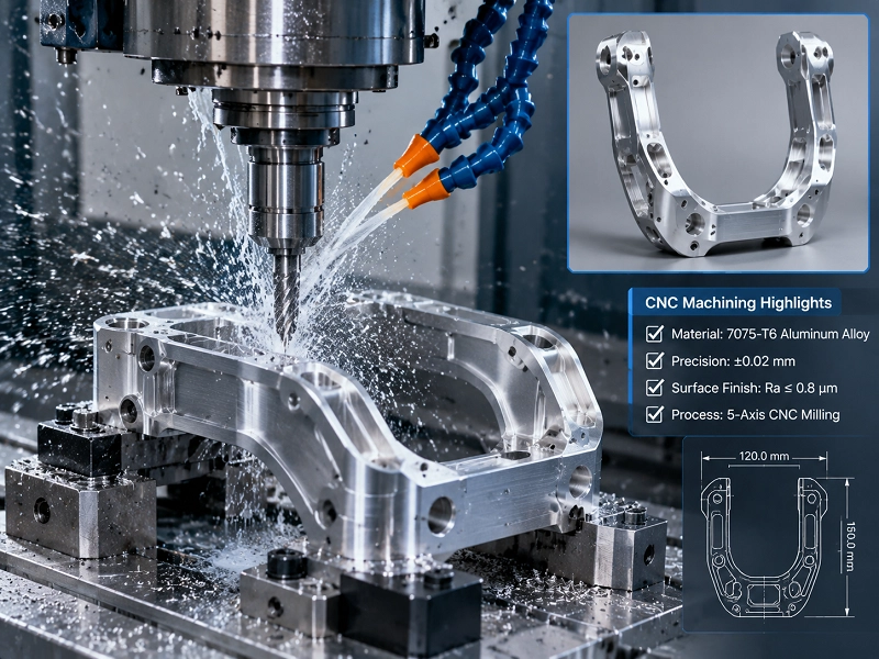
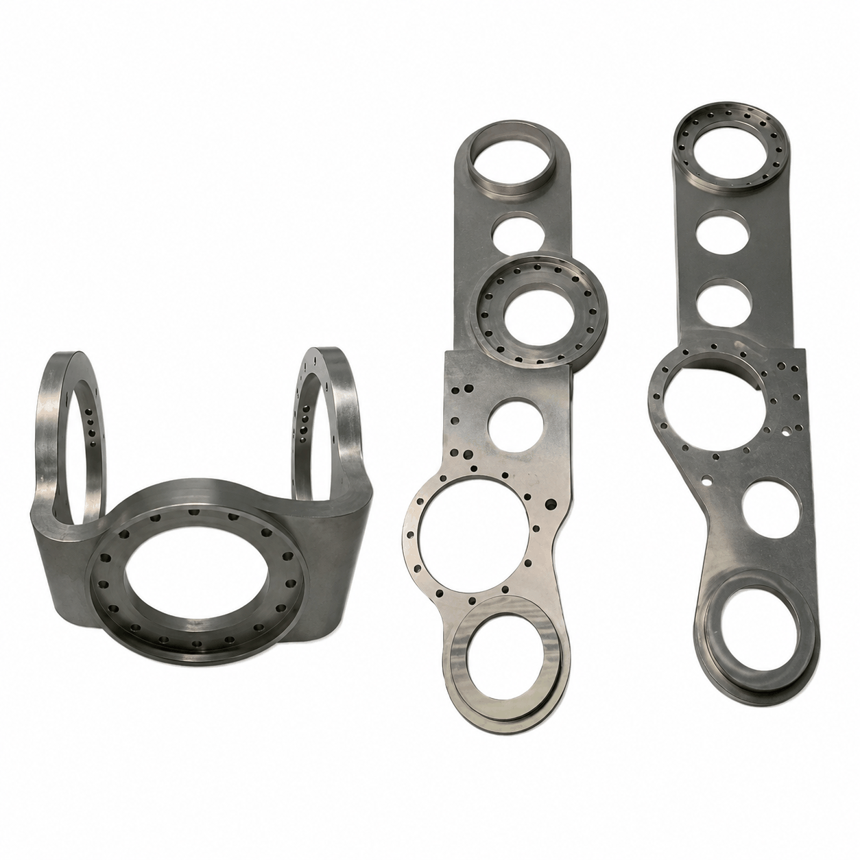
SU-type frames for humanoid robot legs are commonly used at the hip, knee, and other load-bearing lower-limb connection points. The components typically must simultaneously balance lightweight design, rigidity, hole location accuracy, and assembly clearance. Before machining, it is recommended to verify the joint axes, mating part dimensions, primary datum surfaces, and critical dimension protection requirements after surface treatment.
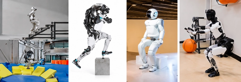
2. CNC machining in common applications for humanoid robots
2.1 U-shaped bracket for the hip joint of a humanoid robot
The hip joint U-frame is a core load-bearing component connecting the torso to the thigh, simultaneously supporting the upper body’s weight and impact loads during walking. Its U-shaped opening houses the hip motor and gearbox, and the bearing bores on the side lugs must be coaxial; otherwise, the robot will experience binding or uneven wear when stepping. The key to CNC machining is completing both side bearing seats and the motor mounting surface in a single setup to ensure coaxiality. Materials typically include 7075 aluminum alloy or TC4 titanium alloy, balancing weight reduction with structural strength.
2.2 Knee Joint Support Frame
The knee joint support frame bears bending and impact loads, making it a structural component close to the ground where inertial effects are significant. It must provide a rigid mounting reference for the knee motor, gearbox, and limit switches, while reducing weight through topology-optimized thin walls and weight-reduction slots. The CNC machining challenge is that thin-walled parts tend to deform during clamping, so segmented machining combined with vacuum suction-cup support is often used. For example, an aluminum alloy knee joint bracket is first roughly milled on the exterior… Shape, then finely machine the bearing housing and mounting surface to ensure interchangeability of the left and right leg components and smooth motion.
2.3 Load-bearing connectors for the lower limbs
The lower limb load-bearing connector links the thigh and shank segments to the joint actuator into a single force transmission chain, with the requirement that no additional lateral forces be generated when transmitting torque. If the pinhole and bearing seat are misaligned, friction will absorb the assistive or locomotion torque, causing the robot’s motion to become jerky. CNC machining typically controls pinholes and bearing seats to within ±0.01 mm and seeks to complete multiple hole patterns in a single setup. Materials can include 7075 aluminum alloy or titanium alloy, with stainless steel bushings press-fitted into locally wear-resistant areas.
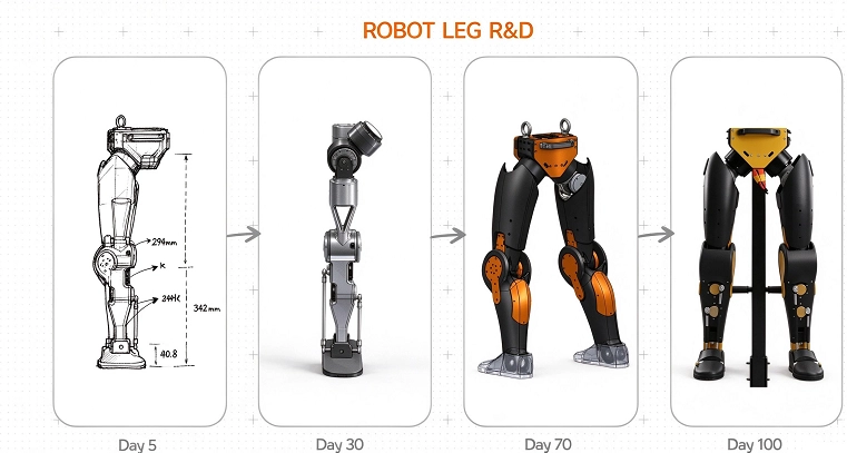
2.4 Leg Joint Structural Component
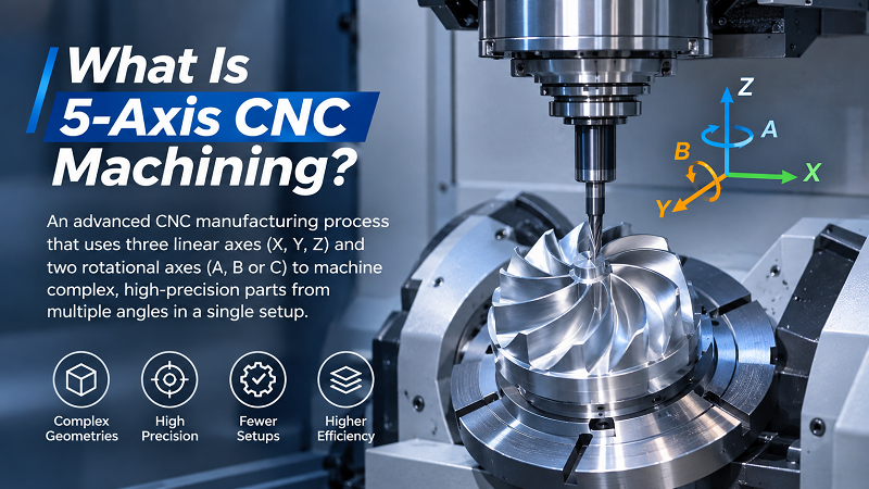
Leg joint structural components include the joint housing, end caps, limit blocks, and cable routing brackets, which must both protect the internal motor and gearbox and provide channels for sensors and cables. These parts feature multiple surfaces, numerous holes, narrow slots, and countersinks; the more times they are flipped and clamped, the greater the accumulated error. A 5-axis CNC machine can complete machining of the joint mounting surfaces, bearing bores, countersinks, and cable channels in a single setup. For example, M4 tapped holes and countersinks on the joint housing can be machined in the same operation, ensuring bolts fit smoothly during assembly and enabling smoother joint operation.
2.5 Bearing Housing Support Bracket
The bearing housing support bracket serves as the “foundation” for the bearing. Its flatness, perpendicularity, and hole spacing directly determine bearing life and joint noise. If the bracket lacks sufficient rigidity or its mounting surface is uneven, the bearing will experience uneven loading, resulting in abnormal noises and premature wear. CNC machining. First ensure the flatness of the mating surface, then precisely bore the bearing holes; if necessary, use grinding to reduce the surface roughness to Ra 0.8 µm. Common materials are 6061 or 7075 aluminum alloy, and the structure should include reinforcing ribs to prevent thin walls from collapsing under bolt preload.
2.6 Lightweight Framework for Robots
The lightweight frame serves as the “skeleton” of the robot’s torso and limbs, comprising 66 components. It must minimize weight while ensuring sufficient stiffness to reduce joint loads and energy consumption. Typically constructed from aluminum alloy profiles or solid CNC-machined parts, it features numerous weight-saving cavities, cable management channels, and mounting holes. Conventional 3-axis machining is inefficient, whereas 5-axis CNC machining can complete complex curved surfaces and angled hole systems in a single setup. For example, the pelvic frame is milled as a single piece from 7075 aluminum alloy, replacing multiple separate parts joined by bolts; this eliminates assembly tolerances and achieves overall weight reduction.
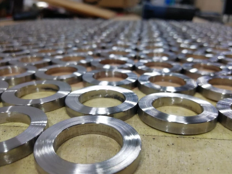
3. What materials are commonly used in CNC machining for humanoid robots?
To ensure a high strength-to-weight ratio and dynamic responsiveness without compromising torsional stiffness, material selection and geometric design should be closely integrated:
3.1 Distal/End Effector Segments (e.g., forearm, ankle)
Prioritize extreme lightweighting (using 7075 aluminum, carbon fiber composites, and engineering plastics) to reduce the moment of inertia of the entire kinematic chain.
3.2 Proximal/High-Stress Base Regions (e.g., hip, shoulder nodes)
Prioritize maximum stiffness and fatigue resistance (Ti-6Al-4V titanium alloy and 17-4PH stainless steel) to prevent elastic or plastic deformation under high mechanical loads.
3.3 Warpage Control in Heavy-Duty Cavity Machining
Excessive material removal in thin-walled structural frameworks can release internal residual stresses, causing parts to warp or bend. Experienced CNC machining shops employ balanced material removal strategies, performing roughing and finishing on opposite sides of the workpiece to tightly control hole locations and the flatness of mounting surfaces.
3.4 Why does 6061 aluminum alloy dominate the field of CNC parts for humanoid robots?
If there is one material that defines the humanoid robot supply chain, it is 6061 aluminum alloy. Lightweight: with a density of only 2.7 g/cm³ — this is crucial when each joint houses a stack of motors, gearboxes, and sensors. High strength and easy to machine: It offers an excellent strength-to-weight ratio, machines cleanly on CNC milling machines, and achieves a high surface finish. Excellent anodizing results: Black hard-anodized treatment offers wear resistance and electromagnetic interference shielding, while delivering the uniform matte finish commonly seen on industrial robots. Cost-effective: Widely used worldwide and much cheaper than titanium or carbon fiber used for structural supports. Compliant with RoHS standards: critical for electronics-intensive equipment and global market access.
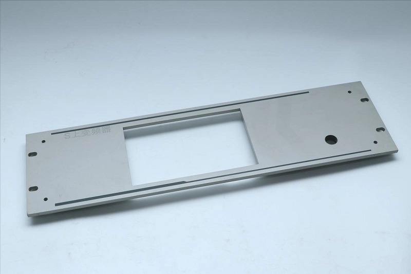
4. The processing technology of the U-shaped frame for humanoid robot legs
4.1. Metal 3D Printing (Additive Manufacturing)
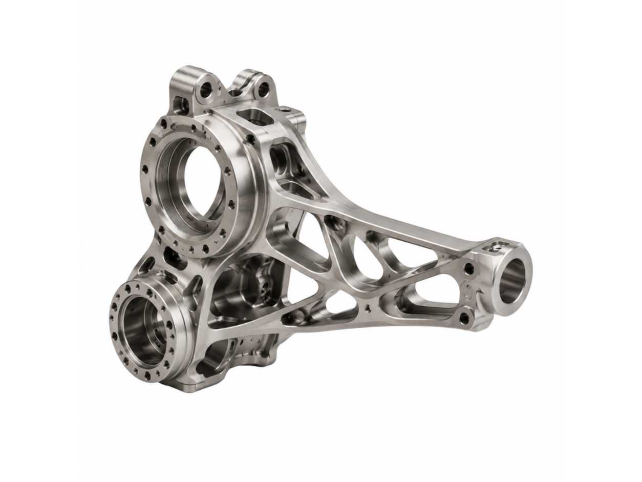
Titanium alloy is used as the substrate. Complex internal lattices and hollow structures were constructed in a single process. Significant weight reduction was achieved while maintaining structural integrity.
4.2. Precision CNC Machining (Subtractive Finishing)
After printing, precision machining was performed on the surfaces of critical features. The bearing housing, mounting interfaces, and connection areas are all machined to high precision. Tolerances for critical assembly features reach ±0.01 mm.
4.3. Post-processing and Surface Treatment
Surface finishing improves overall surface quality; stress relief enhances long-term dimensional stability; and final surface treatment ensures durability and consistency for robotic applications. The final completed section:
The weight is significantly reduced compared to fully CNC-machined parts. High structural strength, suitable for humanoid robot locomotion systems. Precision assembly with tolerances within ±0.01 mm. Optimize the internal topology to improve load distribution.
5. Focus Areas in Machining
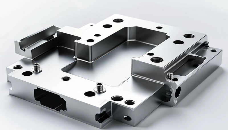
The wall thickness on both sides of the leg’s U-shaped bracket, the opening width, and the bearing and locating holes all affect the coaxiality of the joint assembly. During the quoting phase, it is recommended to clearly specify the primary datum, the joint axis, the dimensions of mating components, and which hole locations require focused inspection. U-shaped structures are susceptible to clamping sequence and material stresses; thin-walled regions, deep cavity locations, and anodizing film thickness can all affect trial assembly. If bearing bores or mating surfaces must remain unaffected by film thickness, protective measures or secondary finishing should be confirmed in advance.
6. Suggestions on the materials and processes of the U-shaped frame for humanoid robot legs
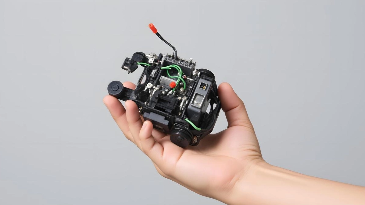
7075 aluminum alloy is suitable for lightweight load-bearing U brackets, 6061 aluminum alloy is suitable for standard validation prototypes, TC4 titanium alloy is suitable for high-strength, lightweight applications, and stainless steel and 40Cr are suitable for high-rigidity or wear-resistant connection areas. Multifaceted features and complex cutout structures should preferably be evaluated using 5-axis CNC machining.

7. What are the surface treatments for the U-shaped frame of humanoid robot legs?
7.1 Sandblasting/Grinding Pre-treatment, Standardized Surface Texture
After CNC machining, the surface of the U-bracket will retain tool marks, step marks, and minute burrs, requiring pre-treatment through sandblasting, grinding, deburring, or polishing. Sandblasting can produce a uniform matte finish on exposed surfaces while enhancing the adhesion of subsequent coatings; for visible surfaces, a grit size of approximately 120–180 mesh is recommended, with clear specifications for scratch grades and color consistency. Special attention should be paid to removing sand from blind holes, threaded holes, and areas near bearing seats to prevent residual grit that could cause assembly issues or surface whitening.
7.2 Hard anodizing or chemical nickel plating to enhance wear and corrosion resistance
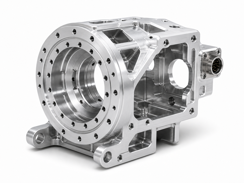
Aluminum alloy U-brackets are commonly anodized, with hard anodizing in particular significantly improving surface hardness, wear resistance, and corrosion resistance, making it suitable for leg load-bearing components subjected to long-term reciprocating motion. If the part requires better electrical conductivity, shielding, or uniform coverage of complex internal cavities, electroless nickel plating can be evaluated. Surface treatment requirements—including coating thickness, masked areas, and reinspection criteria—must be confirmed in advance to prevent assembly tightness issues in bearing bores, pin holes, and mating datum surfaces caused by increased coating thickness.
7.3 Dimensional Compensation and Treatment of Critical Fit Locations, Followed by Re-inspection
Surface treatment should not be a final, after-the-fact step; rather, it should be integrated into DFM and process validation. For bearing bores, locating holes, threaded holes, sealing surfaces, and conductive grounding surfaces, it must be clearly specified whether they are to be masked or left uncoated, and whether compensation allowances are provided. Acceptance dimensions should be annotated separately for the pre-treatment and post-treatment conditions. Prior to shipment, it is recommended to perform a CMM reinspection of critical features, while also checking for color differences, white etching, sand loss, dents, and coating uniformity, to ensure batch-to-batch consistency meets the requirements for complete-machine assembly.

8. What are the key dimensions of the U-shaped frame for humanoid robot legs?
Tolerances, Surface Finish, and Quality Control in Robot Component Manufacturing. In the field of humanoid robotics, the “good enough” concept simply does not exist. Tiny errors across dozens of joints can accumulate, resulting in awkward or unstable robot movements.
8.1 Geometric Tolerances
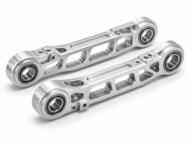
Dimensional tolerances for critical features such as bearing bores, gear shafts, and mating surfaces typically range from ±0.0125 mm to ±0.025 mm (±0.0005 inch to ±0.001 inch). For ultra-precision gear interfaces or sensor mounting seats, tolerances can reach the sub-micron level. Geometric tolerances—such as flatness, perpendicularity, concentricity, and true position—are equally important, if not more so. Bearing housings must not only meet dimensional requirements… It must be properly fitted, and its axis must be perfectly perpendicular to the mounting surface to prevent binding and premature wear.
8.2 Surface Finish Requirements
Surface finish, expressed in microinches (µin) or micro Ra, directly affects bearing performance. Rough bearing surfaces lead to increased friction, heat generation, and rapid wear. Sealing surfaces must be smooth to prevent leaks. Gears require specific surface finishes for optimal lubrication and quiet operation. Typical surface finish requirements span a wide range: 32 µin Ra for noncritical surfaces (good machined finish), versus 8–16 µin Ra or better (near mirror finish) for bearing journals and sealing faces. Achieving these demands precise machining parameters, tool selection, and often secondary operations such as honing or polishing.
8.3 Total Quality Control
Quality control runs throughout the entire manufacturing process. First-article inspection using a coordinate measuring machine (CMM) is mandatory. The CMM employs a touch probe to digitally map the part’s geometry and directly compares it with the original CAD model, thereby verifying every dimension and tolerance. For critical features in high-volume production, on-machine measurement can be performed on CNC machines to enable real-time adjustments. Surface finish is verified using a profilometer. Furthermore, functional tests—such as checking the rolling torque of assembly joints or backlash in gear trains—provide the final validation of machined parts’ performance as an integrated system.
9. What are the inspection and delivery capabilities that a qualified humanoid robot leg U-frame processor should possess?
Key inspection items include bearing bore diameter, coaxiality, split width, locating holes, mounting hole spacing, flatness of mating surfaces, go/no-go thread gauges, and edge burrs. Standard small-batch projects are delivered in approximately 5–10 days; for hard anodizing, test reports, or trial assemblies, confirmation is based on the actual drawings.
10. What are the relevant machining capabilities that a qualified humanoid robot leg U-frame processor should possess?
The U-shaped bracket for humanoid robot legs should not be evaluated in isolation; instead, it should be considered holistically within the same manufacturing process alongside the leg support frame, lower limb components, hip joint parts, foot structural elements, and reducer mounting components. The primary goal of this approach is to standardize joint axes, assembly datums, and inspection requirements. First, the bearing holes and pin holes on the U-shaped bracket have a clear axial alignment relationship with the hip and knee joint components. If each part is machined independently according to its own drawing, accumulated tolerances may become apparent during assembly, leading to joint binding, uneven wear, or abnormal noises. By evaluating the related parts together, a unified datum can be established at the CAM stage, allowing critical hole systems to be completed under the same clamping or datum system as much as possible, thereby reducing axis misalignment caused by multiple setups. Secondly, there are mating surfaces, locating pin holes, and bolted connections between the leg support frame, foot structural components, reducer supporting components, and the U-shaped frame. After establishing a unified assembly datum, it is possible to identify in advance which surfaces are load-bearing mating surfaces and which holes are locators. Hole locations and which areas require surface treatment film thickness compensation to avoid the situation where “a single part passes inspection but cannot be assembled into the complete product.”
Finally, inspection requirements should also be standardized and consistent: coaxiality of joint axes, hole spacing, flatness of mating surfaces, bearing seat tolerances, and chamfers on edges contacting the human body should all be uniformly specified and re-inspected across the entire leg joint chain. This approach not only shortens the prototyping cycle but also reduces the risk of rework during assembly, enabling the U bracket to transition from “a precision component” to a reliable part that can be smoothly integrated into the leg joint system.
11. Information Required for the Quotation
STEP/STP models, PDF drawings, dimensions of mating bearings or motors, material grades, quantities, tolerances, surface treatments, inspection and delivery requirements
12. The role of CAD/CAM and simulation in the machining workflow
CAD/CAM and simulation form the digital backbone that connects humanoid robot part design to manufacturing. The CAD model serves as the single source of truth, encompassing PMI such as dimensions, tolerances, surface finish, and materials. CAM translates this into G-code, generating complex 5-axis toolpaths while performing virtual collision detection and geometric validation. FEA analyzes stress and optimizes the structure before machining. This seamless closed-loop workflow shortens prototyping cycles, reduces material waste, and ensures that manufactured parts meet simulated performance specifications.
13. Why choose Noble as your supplier?
Noble does not just machine one U-shaped frame. It evaluates the leg support frame, hip joint parts, and reducer matching parts together. This helps unify the joint axis and inspection datum. Five-axis one-setup machining keeps the axis from shifting. Segmented thin-wall machining controls deformation. Bearing seats are finished to ±0.01 mm. Surface treatment protects where needed and adds wear resistance where needed. Choosing Noble means choosing a partner who understands how the whole leg is assembled.