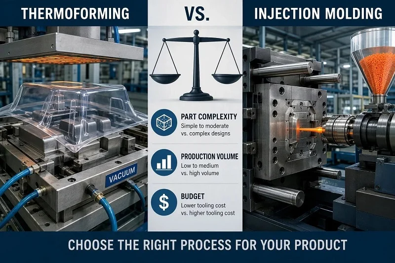
The question of thermoforming vs injection molding rarely has a single right answer. It has a right answer for a particular part, a particular annual volume, and a particular budget — and those three inputs can point in opposite directions. A large, gently contoured equipment cover that will sell a few hundred units a year and may still change shape is a very different problem from a palm-sized housing with snap fits, bosses, and a five-year demand forecast in the hundreds of thousands.
This guide works through the comparison in the order that decisions actually get made: how each process forms a part, what that means for tooling cost and lead time, where the per-part cost curves cross, which materials each route can handle, what design rules and tolerances you can realistically specify, and which applications each process serves. It closes with how both compare against adjacent routes — 3D printing, blow molding, CNC machining, and die casting — a summary matrix you can use as a starting point, a section on partnering with NOBLE for injection molding work, and answers to the questions buyers most often bring to a first quote.
Thermoforming vs Injection Molding at a Glance
| Factor | Thermoforming | Injection Molding |
| Tooling cost | Low; single-sided molds in aluminum, composite, wood, or cast resin. Often several times less than an equivalent injection mold. | High; two precisely machined halves, typically steel, built to withstand high clamp pressure. |
| Tooling lead time | Weeks. Development cycles can run as short as four to six weeks depending on the part. | Usually several months for design, machining, and validation. |
| Typical tolerance | About ±0.030 in (±0.75 mm) on tool-side features for vacuum forming; about ±0.015 in (±0.4 mm) with pressure forming and on CNC-trimmed edges. | Routinely around ±0.05 mm, because the part is constrained on both sides. |
| Wall thickness | Varies. The sheet thins where it is drawn; a part near its draw limit may retain only 20–50% of starting gauge at the deepest corner. | Uniform and controlled through the tool. |
| Best-fit volume | Prototype through low-to-medium volume; competitive at higher volume for large parts. | High volume, where tooling amortizes across the run. |
| Material range | Thermoplastic sheet: PP, ABS, polystyrene, PET, polycarbonate, PVC, acrylic, polyethylene, and others. | Broad range of thermoplastic resins in pellet form, including engineering grades and filled compounds. |
| Surface detail | Good with pressure forming; limited with straight vacuum forming. | High cosmetic and functional detail, including texture, ribs, bosses, and undercuts with tooling provisions. |
| Secondary operations | Trimming is normally required, plus drilling, bonding, and CNC machining. | Parts usually eject close to finished geometry with less post-processing. |
Read the table by row, not by column. On tooling cost, thermoforming wins almost every time; on tolerance and wall uniformity, injection molding does. Neither row decides the project on its own. A part with a generous tolerance band and a large footprint may stay with thermoforming well past the volume where a small precision component would have moved to injection molding, because injection tooling and press requirements scale unfavorably with part size. Use the matrix to eliminate options, then run the arithmetic for your own part before committing to a tool.
How Thermoforming and Injection Molding Works
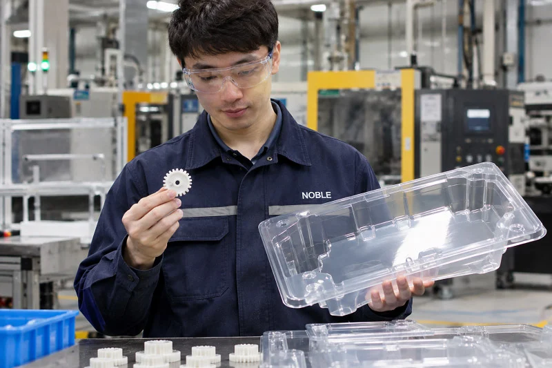
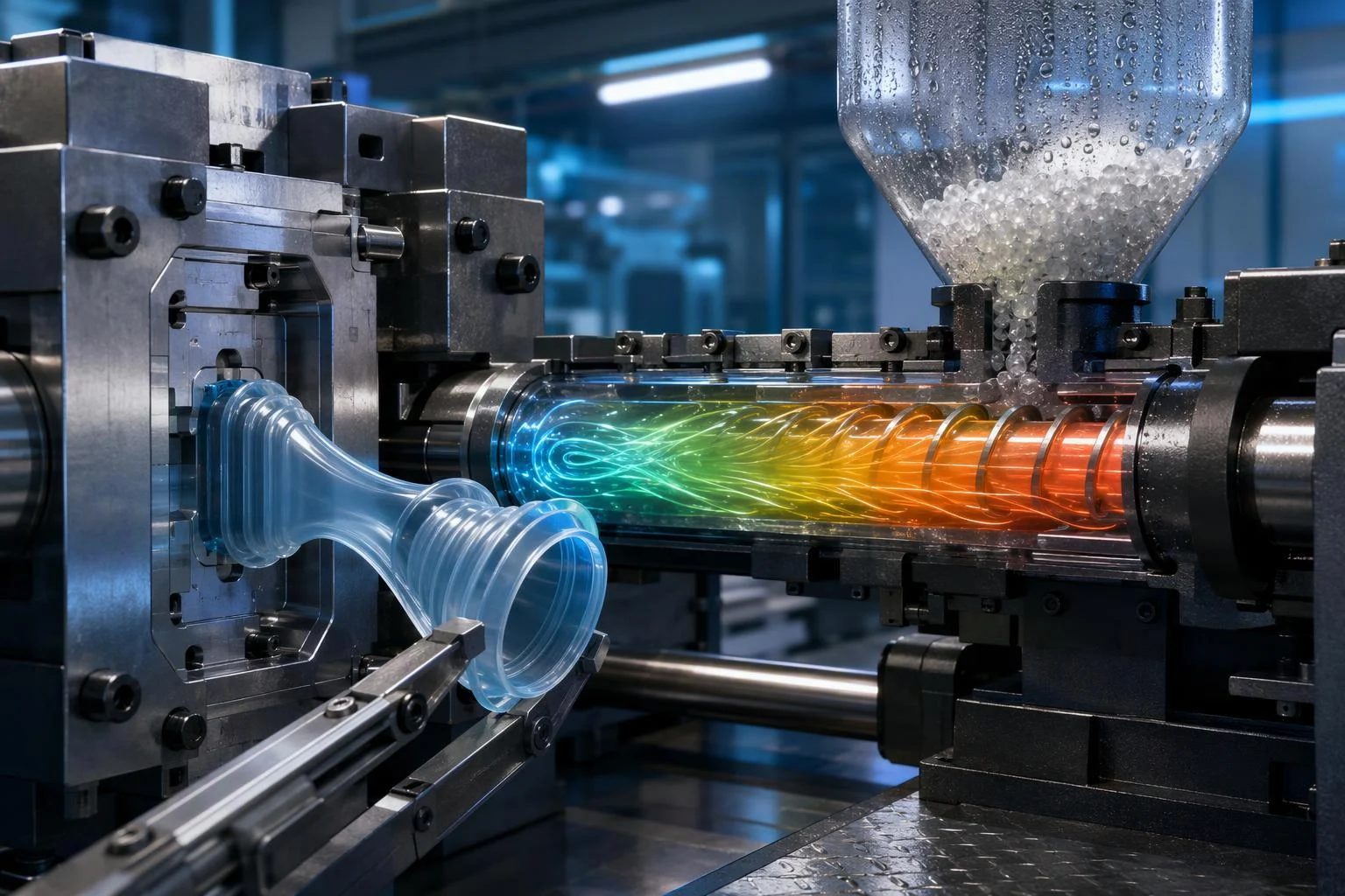
The whole comparison follows from one mechanical difference. Thermoforming takes a flat sheet that has already been extruded to a fixed gauge and pulls it against a single mold surface under relatively low pressure. Injection molding takes pellets, melts them, and forces the melt into a closed cavity under high pressure so the plastic is shaped on every surface at once. Feedstock form, tooling architecture, pressure, and post-processing all follow from that split.
The Thermoforming Process Step by Step
The cycle begins with clamping a thermoplastic sheet in a frame and conveying it into a heating station. Infrared heaters are the usual heat source because they allow zonal control across the sheet, avoiding cold spots that resist forming and hot spots that thin or blemish the surface. The heated sheet then moves to the forming station, where vacuum, compressed air, a mechanical plug, or a combination of these forces presses it onto or over the mold. Forced air or water-cooled molds then extract heat until the part is rigid enough to handle.
Trimming is a separate step. CNC routers, die cutters, or high-speed saws cut the finished parts out of the surrounding skeleton, and that skeleton is typically regranulated and reused. The main variants differ in how much forming force and detail they deliver:
- Vacuum forming uses atmospheric pressure alone. It is the simplest and cheapest route, well suited to large parts that do not need sharp definition.
- Pressure forming adds compressed air on the opposite side, raising forming force to several times atmospheric pressure. That buys sharper corners, deeper draws, and surface texture that approaches molded detail.
- Drape forming places the heated sheet over a male mold and lets gravity and mechanical pressing shape it, which suits large, gently contoured panels with minimal tooling.
- Twin-sheet forming heats two sheets simultaneously and presses them against opposing molds, fusing them where they meet to create hollow, double-walled structures such as ducts, pallets, and rugged enclosures.
The Injection Molding Process Step by Step
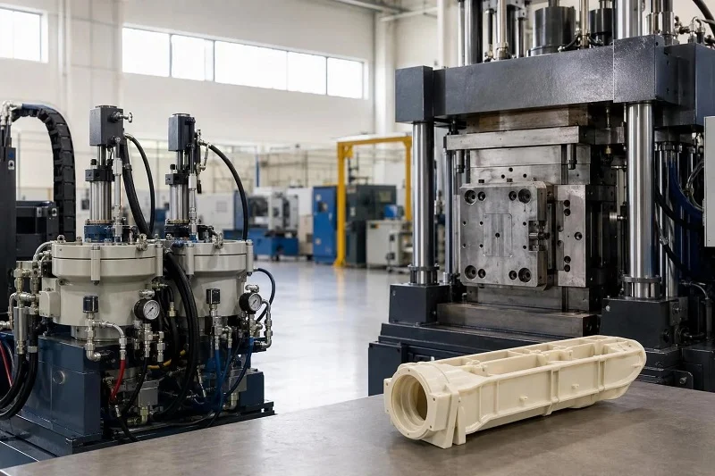
Injection molding starts with pellets rather than sheet. The resin is melted in the machine’s barrel and injected under high pressure into a machined two-sided mold — a cavity and a core — that has been designed for the specific part. The melt fills the gap between the two halves, is held under pressure while it cools, and the mold opens so the part can be ejected. Depending on gate design, the part either separates from the runner automatically or is cut free.
Because both halves are precisely machined, the process constrains the part on all sides. That is the source of its tolerance capability: the wall thickness, the outer surface, and the inner surface are all defined by steel rather than by how a sheet happened to stretch. It is also why the part usually needs no secondary trimming, and why the tooling investment is substantially higher.
Where the Two Processes Diverge
Five differences do most of the work downstream:
- Tooling architecture. One-sided molds versus matched cavity-and-core sets. This drives the tooling cost gap and the ease of modifying a design.
- Forming pressure. Roughly one atmosphere for vacuum forming, up to several bar for pressure forming, and far higher for injection. Pressure determines how sharply the material can be forced into corners and fine detail.
- Sheet of a fixed gauge versus pellets that can be melted and distributed freely. Sheet gauge sets the wall thickness ceiling; pellets do not.
- Net shape versus trim. Injection molding ejects near-finished parts; thermoforming produces a formed sheet that must be trimmed and often drilled or machined.
- Design freedom. Because the sheet stretches, thermoformed geometry is constrained by draw ratio and thinning; because the melt fills a machined gap, injection-molded geometry is constrained by draft, wall uniformity, and tooling complexity instead.
Each of those differences reappears in the sections that follow — in tooling cost, in the per-part cost curve, in material selection, and in the design rules you can specify.
Tooling Cost and Lead Time
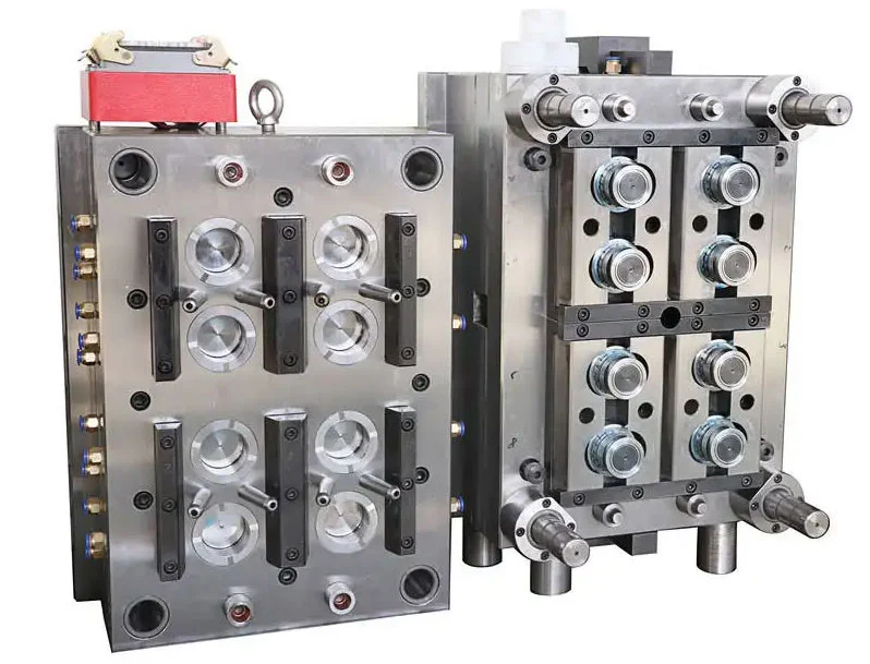
Tooling is often the deciding factor, particularly for readers whose volumes are uncertain or whose design is still moving. The gap between the two processes here is large and consistent.
Tooling Materials and Cost Drivers in Thermoforming
Thermoforming molds are inexpensive because forming pressures are low and a single-sided tool is usually sufficient. Molds are commonly made from aluminum, epoxy composite, wood, or cast resin, chosen according to production volume and required surface quality. At higher volumes, aluminum molds with integrated cooling channels reduce cycle time and improve dimensional consistency. Aluminum is also far cheaper to modify than hardened steel, which matters when a design is still evolving: a change to a thermoforming tool is a modest expense, while a change to an injection mold can be a significant one.
Injection Mold Investment and Lead Time
Injection molds cost more because they are two precisely machined halves built to survive high clamp pressure and, in production tooling, hundreds of thousands of cycles. Mold design, machining, fitting, and validation all take time. Lead times for injection molding usually run to several months, against thermoforming development cycles that can be as short as four to six weeks depending on the part.
The higher tooling cost is best read as an investment amortized across volume rather than as a penalty. Spread over a large run, a mold that costs tens of thousands of dollars can contribute only cents to each part. Spread over a few hundred parts, the same mold is a serious burden — which is exactly why the volume question in the next section matters so much.
Cost per Part and Production Volume
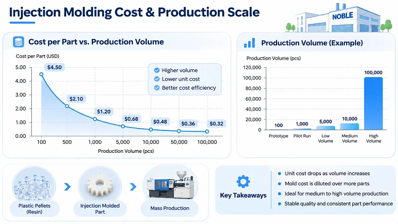
Where each process wins on unit cost is the question most buyers actually need answered, and it is also the one where generic numbers mislead most easily. The honest structure of the answer is a typical range plus a warning that your part specifics move the crossover.
The Volume Break-Even
As a working rule, thermoforming tends to be the more economical choice below roughly 3,000 parts a year, and injection molding tends to win above roughly 10,000. Between those figures, the decision requires actual break-even arithmetic using your own quotes: tooling cost, per-part price from each route, and expected annual usage.
Treat those thresholds as typical ranges, not universal rules. Part size is the biggest shifter. For small and medium parts, the crossover commonly falls somewhere between 3,000 and 10,000 units. For large parts — enclosures, panels, agricultural covers — thermoforming often remains the more economical choice at much higher volumes, because injection tooling and press requirements scale unfavorably with part size. Lead time and design stability shift the crossover too: if the design is likely to change, the cost of modifying an injection mold belongs in the comparison.
Why Cycle Time and Scrap Move Unit Cost
The cost mechanics differ on both sides of the equation. Injection molding’s cycle-time efficiency is what drives part cost down at high volume: once the tool is paid for, each additional part costs relatively little, and the process uses material efficiently because wall thickness is controlled exactly.
Thermoforming carries material scrap that injection molding largely avoids. The web between nested parts and the trim waste can represent a substantial share of raw material input — in some estimates 20–50% — so material utilization and cycle time on the specific machine are the highest-leverage cost drivers. A 10% error in utilization swings material cost by roughly 12%. Most thermoformers regrind and blend that scrap back in house, and tight nesting and multi-up tools cut it substantially, but it remains a real input to the per-part price.
Against that, thermoforming’s much lower tooling amortization offsets its higher per-part cost at low volumes. The two effects cross somewhere in the middle band, and where they cross is a function of your part, not of a published table.
Materials: What Each Process Can Handle
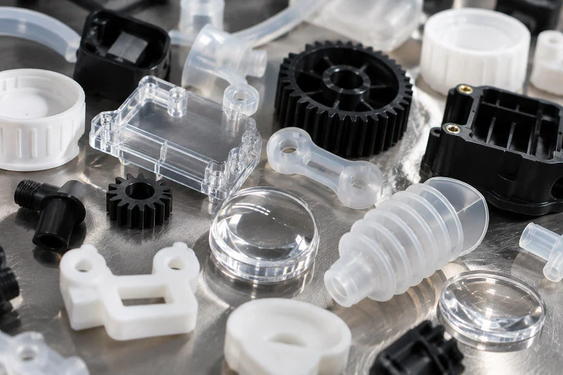
Both processes work with thermoplastics, but the feedstock form narrows what is practical in each case and, in turn, constrains the geometry you can design.
Thermoplastic Sheet Materials for Thermoforming
Thermoforming handles a wide range of sheet materials, and selection is driven by end use:
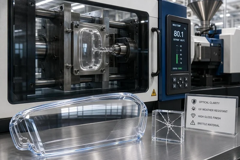
- Polycarbonate for impact resistance and optical clarity.
- PET for food-contact applications, where its chemical stability and low gas permeability matter.
- ABS for durable consumer goods, appliance housings, and equipment covers.
- Polypropylene for chemical resistance and living-hinge behavior in packaging and containers.
- Polystyrene and high-impact polystyrene for cost-effective packaging, trays, and clamshells.
- PVC for signage, construction products, and applications needing flame or chemical resistance.
Each material has its own forming temperature window and sensitivity to heating rate, which sets oven dwell time and how precisely temperature must be controlled across the sheet. Uneven heating produces uneven wall distribution, so the oven is a quality tool as much as a cost center.
Resin Selection for Injection Molding
Injection molding draws from a broad range of thermoplastic resins in pellet form, including engineering grades, glass- and mineral-filled compounds, and flame-retardant formulations. Material choice interacts with mold design in ways that sheet does not: each resin has its own shrinkage behavior, flow characteristics, and drying requirements, and those determine gate location, cooling layout, and cycle time. Filled grades can add stiffness but introduce directional shrinkage and warpage that the tool must be designed around. The practical consequence is that material selection and mold design are decided together, early.
How Material Choice Constrains Design
Feedstock form is the constraint that matters most. In thermoforming, the sheet gauge you buy sets the achievable wall thickness, and because the sheet thins as it stretches, the gauge must be chosen around the thinnest section the part requires. In injection molding, wall thickness can be varied through the tool, so thick and thin sections can coexist in one part — subject to the usual rules about gradual transitions and avoiding thick masses that sink or warp.
On sustainability, both processes use thermoplastics, which are remeltable and recyclable in principle, unlike thermosets that form permanent chemical bonds and cannot be remolded. Injection molding generates runner and sprue waste, which hot-runner systems can eliminate entirely at added tooling cost, and cold-runner scrap can usually be reground and blended back at moderate ratios. Thermoforming generates skeleton and trim scrap, which is likewise commonly reground in house. Recycled-content grades are increasingly available for both routes, though they can introduce variation in color, flow, and mechanical properties that needs validation for appearance-sensitive or safety-critical parts.
Design Rules and Tolerances
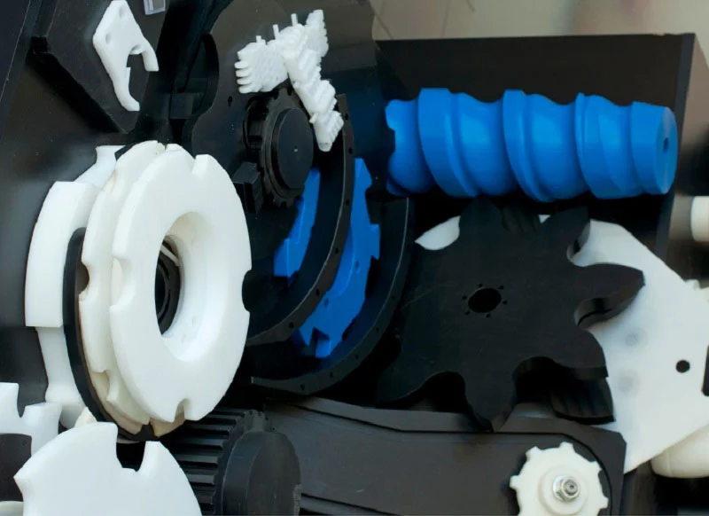
The design-side comparison is what you need for a DFM conversation. Draft, radii, draw ratio, wall thinning, and tolerance all behave differently, and the differences are large enough to change a part’s concept rather than just its details.
Draft Angles, Radii, and Draw Ratio in Thermoforming
Thermoformed sheet cools against the tool surface and can vacuum-lock without adequate relief, so draft is not optional. Typical guidance:
- Draft on male tools: about 3–5° per side, moving toward 5–7° for draws deeper than the part width.
- Draft on female tools: about 1–2° per side, since the part shrinks away from the cavity.
- Inside radius: a minimum of one times sheet thickness, with 2–3× thickness much better. Small radii are where the sheet stretches fastest and thins most, and vacuum alone cannot force material into a tight corner.
- Draw ratio (depth to width): keep as close to 1:1 as possible for vacuum forming. Plug assist can extend achievable depth considerably, but deeper draws thin the corners past usable wall.
Formed wall retention is typically about 50% of starting gauge and can fall to around 20% at the deepest corner. That single fact sets the sheet gauge you must purchase: you buy sheet by the thinnest section you need, not by the average.
Wall Thinning and Its Cost Consequences
Because corners and deep draws stretch the sheet, the designer must specify a starting gauge thick enough that the thinnest point still meets the functional requirement. This reframes the specification from “3 mm everywhere” — which is not achievable in a deep draw — to “at least X mm in these critical zones,” which is both achievable and verifiable.
Generous fillets distribute material and reduce webbing risk, where the sheet folds on itself between features. Step changes in wall thickness should be avoided: they create chill marks and differential shrinkage that show up as warpage after trimming. And because formed parts continue to relax stresses for weeks, a part measured fresh off the machine may shift measurably over the following month; tight-tolerance applications often call for measurement at 24 hours and again at 7 days, with annealing used to accelerate stabilization.
Tolerance Capability Compared
The realistic tolerance bands differ by roughly an order of magnitude:
- Thermoforming: about ±0.030 in (±0.75 mm) on tool-side features for vacuum forming, tightening to about ±0.015 in (±0.4 mm) with pressure forming and on CNC-trimmed edges. The non-tool side absorbs all sheet thickness variation, so dimensions taken from that surface carry the material’s gauge tolerance as well.
- Injection molding: routinely around ±0.05 mm, because both cavity and core are precisely machined and the part is constrained on all sides.
For your part specification, the consequence is direct. If a critical feature must hold a tolerance tighter than a few tenths of a millimeter on both sides, thermoforming is unlikely to satisfy it without secondary machining, and injection molding is the natural route. If the tolerance band is generous and the part is large, thermoforming’s wider band is rarely the limiting factor — and the money saved on tooling can be spent elsewhere.
Applications: Where Each Process Fits
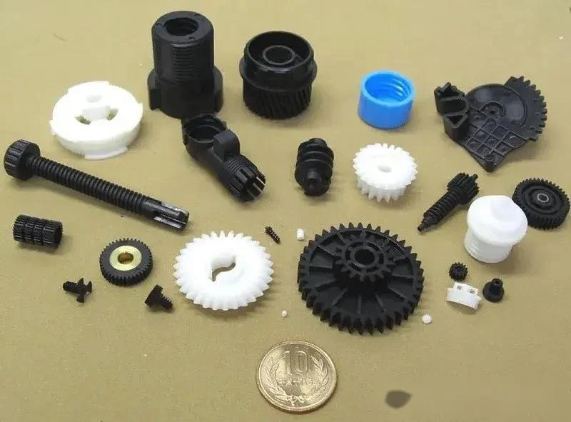
Application patterns follow from the economics and design rules above. Locating your own part among them is often faster than working through the numbers from scratch.
Typical Thermoforming Applications
Thermoforming’s sweet spot is large, thin-walled parts at low-to-medium volume, and in some large-part categories at high volume as well:
- Food and pharmaceutical packaging: trays, blister packs, and clamshells, usually thin-gauge and roll-fed.
- Automotive: interior panels, door liners, and underbody shields.
- Medical: device housings and single-use surgical trays.
- Aerospace interiors: cabin liners and luggage bins.
- Consumer and industrial goods: appliance housings, equipment covers, recreational equipment, and twin-sheet hollow structures such as ducts and pallets.
Typical Injection Molding Applications
Injection molding suits high-volume, tight-tolerance parts with complex geometry and molded-in functional detail: durable consumer goods, precision housings, and components that need ribs, bosses, snap fits, undercuts, or sealing features. These are the requirements that are difficult, expensive, or unreliable to create through thermoforming alone, and they are why the tooling investment pays off across a large production run. Injection molding is also the usual route for small and medium parts made in large numbers, where per-part cost dominates the total.
Medical and Regulated Applications
Both processes serve regulated markets, but the documentation burden differs by product class and market rather than by process alone. Medical and automotive programs usually add traceability, validation, and change-control requirements on top of the manufacturing specification. Products sold in different regions may face different demands: electrical products may need UL recognition, IEC-related testing, RoHS and REACH documentation, or region-specific environmental declarations. For electrically sensitive, outdoor, flame-retardant, food-contact, or medical applications, the required standards should be defined before tooling begins, and resin or sheet traceability requested where appropriate. The applicable requirements depend on the market and the product class, so they are worth confirming early rather than assuming.
Thermoforming vs Injection Molding vs with Other Processes
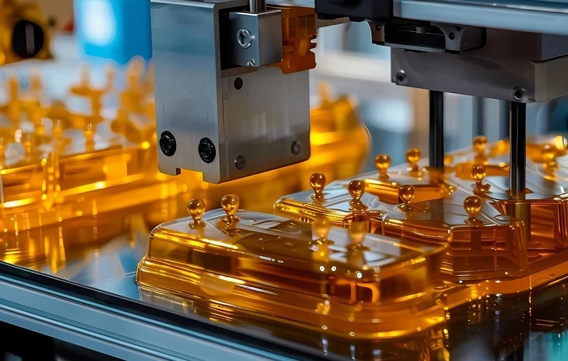
Thermoforming vs injection molding is not the only choice on the table. Placing both in a wider landscape helps confirm whether a third route fits better before you commit to a tool.
3D Printing
Additive manufacturing suits prototypes and low-volume complex geometry without tooling, and it is often the fastest way to hold a design in your hand. At production volumes, thermoforming and injection molding offer better economics and material properties, and the surface finish and repeatability of a molded part are generally superior. The two routes are complementary rather than competing: 3D-printed tooling can serve as a bridge for early thermoforming runs, letting you validate fit and market response before cutting an aluminum mold.
Blow Molding
Blow molding owns the hollow-part niche — bottles, jars, and containers — where a parison is inflated against a mold cavity. Thermoforming produces parts derived from flat sheet: trays, covers, panels, and enclosures. Injection molding produces solid, detailed components. If the part is a bottle, none of the sheet-or-cavity comparisons apply; if it is a housing with internal features, blow molding is not a candidate.
CNC Machining
Subtractive machining suits tight-tolerance metal and plastic parts at low-to-medium volume without mold investment, and it is the standard route for one-off and bridge production. Molding processes win on per-part cost at higher volume and on repeatability of complex molded detail: a machined pocket is a toolpath, while a molded rib is free once the tool exists. For parts where the geometry is simple and the volume low, CNC can undercut both molding routes on total cost.
Die Casting
Die casting is the metal-part counterpart to injection molding: molten metal forced into a steel die at high volume. The choice between molding plastics and casting metal is driven by material requirements — strength, temperature, conductivity, weight — rather than by the forming method alone. Where a plastic part meets the mechanical and thermal requirements, thermoforming or injection molding will usually be cheaper; where it does not, the comparison shifts to which metal process fits.
Choosing NOBLE to Support Your Injection Molding Project

Once the comparison points toward injection molding, the next decision is who builds the tool and runs the parts. NOBLE is a leading Chinese contract manufacturer and a Sino-British joint venture, recognized by the government as a National High-tech Enterprise, with more than 10 years of experience in custom manufacturing. Our service capability and professional manufacturing capability are built to help customers move a project efficiently from prototype to mass production.
We are certified to ISO 9001:2015 and ISO 13485:2016, so quality management and medical-device quality requirements are addressed within the same manufacturing organization. We provide a full service from design to assembly — not production alone. That means design and DFM support, prototyping, tooling and molding, machining, inspection, finishing, and assembly can be coordinated under one team rather than split across separate vendors.
For an injection molding project, that combination matters at the points where programs usually stall: reviewing part geometry and draft before the tool is cut, selecting a resin and confirming its shrinkage and drying behavior, planning inspection around the tolerances that actually matter, and keeping the transition from prototype to recurring production in one accountable place. Our real-time pricing approach aims to return a professional quote within 24 hours of an RFQ with the necessary information, and our in-house capabilities and inspection equipment support parts made to strict tolerance and quality standards. If you are weighing thermoforming vs injection molding for a specific part and want a manufacturing partner for the molding route, our team can review the design and help you plan the path from concept to volume.
FAQs of Thermoforming vs Injection Molding
How Do I Decide Between Thermoforming and Injection Molding for My Part?
Work through four filters in order. First, volume: below roughly 3,000 parts a year, thermoforming usually wins on total cost; above roughly 10,000, injection molding usually does. Second, geometry and tolerance: if the part needs tight tolerances on both sides, ribs, bosses, or snap fits, injection molding is the realistic route; if it is large and thin-walled with a generous tolerance band, thermoforming is. Third, tooling budget and design stability: if the design may still change, the lower cost of modifying a thermoforming tool is a real advantage. Fourth, lead time: weeks versus months. The summary matrix at the top of this guide is a useful starting point, and the break-even discussion explains how to run the arithmetic for the middle band.
How Does Wall Thinning Affect Thermoformed Part Design and Cost?
Because the sheet stretches, formed wall retention is typically about 50% of starting gauge and can fall to around 20% at the deepest corner. Draw ratio, corner radii, and draft all influence how much thinning occurs. The commercial consequence is that the starting sheet gauge must be specified around the thinnest point that must meet the functional requirement, not around the average — so a deeper draw or a sharper corner effectively raises the material cost of the part. Keeping draw ratios near 1:1, using generous fillets, and considering plug assist or pressure forming are the main levers for controlling it.
At What Production Volume Does Injection Molding Become Cheaper?
As a typical range, injection molding tends to win above roughly 10,000 parts a year, thermoforming below roughly 3,000, with the middle band requiring actual break-even math. Those figures are not universal thresholds. Part size, tooling cost, expected product life, and the likelihood of design changes all shift the crossover, and for large parts thermoforming can remain more economical at much higher volumes.
How Do These Processes Compare with 3D Printing, Blow Molding, CNC Machining, and Die Casting?
3D printing suits prototypes and low-volume complex geometry without tooling. Blow molding owns hollow parts such as bottles and containers. CNC machining suits tight-tolerance parts at low-to-medium volume without mold investment. Die casting is the metal counterpart to injection molding, chosen when metal properties are required. Thermoforming and injection molding remain the two production routes for thermoplastic parts, with the choice driven by volume, size, tolerance, and design stability.
Which Materials Can Each Process Handle?
Thermoforming works with thermoplastic sheet — polypropylene, ABS, polystyrene, PET, polycarbonate, PVC, acrylic, and polyethylene among others — selected for end-use properties such as impact resistance, clarity, or food contact. Injection molding draws from a broad range of thermoplastic resins in pellet form, including engineering and filled grades. The feedstock form constrains what is practical: sheet gauge limits achievable wall thickness in thermoforming, while pellet-based molding allows wall thickness to be varied through the tool.
How Do Validation and Documentation Differ for Medical and Industrial Parts?
Medical and automotive work typically adds traceability, validation, and change-control requirements beyond the basic manufacturing specification. Regional market requirements also vary: electrical products may need UL recognition, IEC-related testing, RoHS and REACH documentation, or region-specific environmental declarations. The applicable requirements depend on the market and the product class, so they should be defined before tooling begins.
Final Verdict: Which Process Should You Choose?
The honest answer to thermoforming vs injection molding is that it depends — but it depends on a short list of things you can check.
Choose thermoforming when the part is large and thin-walled, annual volume is low to medium, the timeline is tight, the tooling budget is small, and the design may still change. Weeks-long tooling, low mold cost, and cheap modification make it the lower-risk route while demand is unproven. For large panels, covers, and enclosures, it can also stay competitive at volumes where small parts would long since have moved to injection molding.
Choose injection molding when the part is small to medium, the volume is high, the tolerances are tight, and the geometry needs ribs, bosses, snap fits, or molded-in detail on both sides. The tooling investment is real and the lead time is measured in months, but across a large run the per-part cost falls well below what thermoforming can offer, and the repeatability of a machined two-sided tool is difficult to match.
What it depends on, concretely: annual volume and expected product life; part size and draw depth; tolerance requirements on each surface; whether the design is locked; tooling budget and lead time; and material requirements that may rule one route out entirely. Answer those six questions and the decision usually makes itself. Where the answers land in the middle band, run the break-even arithmetic with real quotes rather than relying on typical ranges — and if the comparison points toward molding, NOBLE can review the design and support the project from prototype through production.