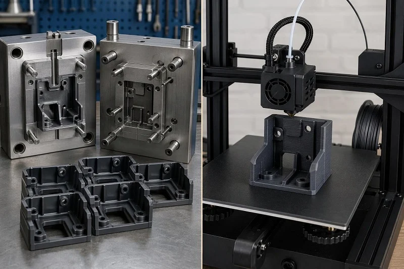
Both injection molding and 3D printing turn a CAD file into a plastic part, but they commit you to very different upfront costs, tolerances, material options and lead times. That is why the injection molding vs 3D printing decision is rarely settled by asking which process is “better.” It is settled by asking which process fits the part, the volume and the stage your design has reached.
This comparison is built from published process descriptions, tolerance and cost data, and peer-reviewed dimensional-accuracy studies rather than a hands-on lab test. It covers how the two processes differ mechanically, where the tooling investment pays for itself, what precision and surface finish each delivers, which materials each can run, how quickly each puts a part in your hand, what geometry each enables, and when a print-then-mold route makes sense. A section on how NOBLE supports both routes follows before the FAQs.
Injection Molding vs 3D Printing: How the Two Processes Actually Differ
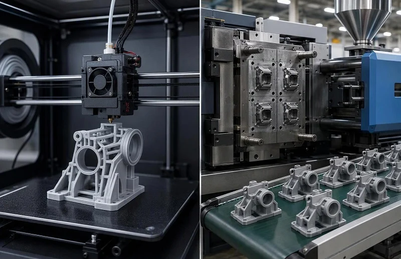
The mechanical difference between the two processes generates almost every trade-off that follows.
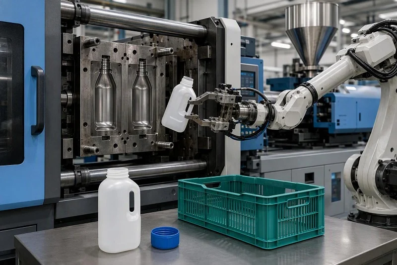
Injection molding injects molten polymer under pressure into a machined metal cavity, holds it while it cools, and ejects a solid part when the mold opens. The tool — the mold — is a fixed piece of precision hardware. Its cavities define the part’s shape, its cooling channels define how fast the polymer solidifies, and its ejector system defines how the part leaves the machine. Because the tool is expensive to make and expensive to change, its cost has to be spread across every part it produces.
3D printing builds the part additively, layer on layer, directly from a digital file. There is no cavity and no tool. The machine’s motion system and the material feed define the geometry, which means the first part and the thousandth part are produced by essentially the same operation.
That single difference — tool or no tool — explains the rest of the comparison:
Cost Structure
Molding front-loads cost into tooling and then drives per-part cost down with volume. Printing has almost no upfront cost and a per-part cost that stays roughly flat whether you order one part or five hundred.
Tolerance Behavior
A molded dimension is the end result of resin shrinkage, cooling, warpage and process conditions acting inside a fixed cavity. A printed dimension is the end result of layer adhesion, build orientation, machine calibration and post-processing.
Design-Change Economics
Altering a cut mold means cutting metal, re-qualifying the tool and re-sampling. Altering a printed design means editing the file and running another build.
Every section below returns to this premise: the mold is an asset you amortize, and the printed file is a variable you can change.
Cost: When Does Tooling Pay for Itself?

The cost comparison is arithmetic, not a slogan, and the arithmetic starts with the tool. Published figures for a consumer-electronics enclosure in ABS put aluminum prototype tooling at roughly $18,000–$50,000 and hardened production steel at roughly $50,000–$200,000 (break-even analysis).
Amortization turns those totals into a per-part figure. Spread across 100,000 parts, the tooling adds about $0.50–$2.00 per part. Spread across only 1,000 parts, the same tool adds about $18–$200 per part. Printed ABS parts of similar size run roughly $8–$35 each regardless of volume, depending on infill, support and finish.
That gives you a working rule: the break-even volume is the point where molded unit cost — material, processing and tooling amortization combined — falls to the printed unit cost. It is not a fixed number. Part size, geometry complexity and required tolerance all move it, sometimes by an order of magnitude, so the only reliable figure is the one you calculate for your own part.
Two further cost drivers deserve a place in that calculation:
Yield And Secondary Operations
Printed parts often need support removal, surface finishing and sometimes post-cure, which can add several dollars per part in labor. If a print run loses parts to warpage or support failure, the effective cost per shipped part rises above the machine cost. A mature molded tool in a controlled process typically runs at very high yield, with scrap contributing only a fraction of a percent. Compare delivered-per-specification cost on both sides, not machine output cost.
Cycle Time
Machine time is roughly half of total molded part cost, so cycle efficiency is the largest variable cost factor in molding. A 25% cycle-time improvement can reduce per-part cost by 15–20% (cycle-time analysis). This is one reason a well-designed tool with optimized cooling and gate placement costs more upfront but earns that back in production.
Cavity count belongs in the same calculation. More cavities raise tool cost — roughly 15–30% per added cavity on simpler parts — but spread machine time across more parts per cycle (tooling cost drivers). Match cavity count to realistic annual volume rather than an optimistic forecast; a tool built for demand that never arrives is the most common way a molding project loses money.
Precision and Surface Finish: What Tolerances Should You Expect?
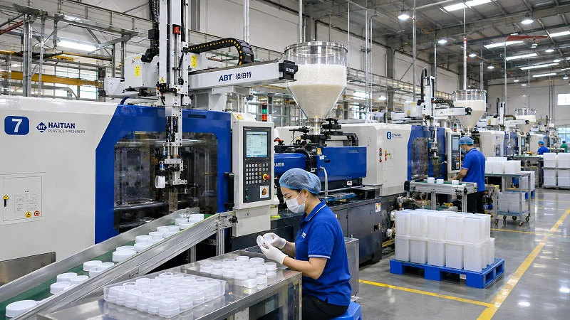
Molding has no single typical tolerance, and any table that offers one should be read with caution. A molded dimension is the end result of resin shrinkage, processing conditions, part geometry, warpage and uneven cooling. Semi-crystalline and filled resins shrink differently in different directions, and long dimensions accumulate more shrinkage than short ones.
The practical approach is to tighten only the dimensions that carry fit, assembly, sealing or motion, and let general tolerances cover the rest. The current standard for molded plastic parts, ISO 20457:2026, separates general tolerances — defaults covering ordinary features — from direct tolerances applied to individual callouts, and it also sets out the limits of what is technically manufacturable (tolerance guidance). A drawing that tightens every dimension spends money on precision the part does not need, and it can push a stable process outside its capability band.
Printing tolerances are process-specific, and each figure carries conditions:
- SLS PA12: about ±0.3%, with a lower limit of ±0.3 mm, is a widely used service specification.
- Industrial FDM: the greater of ±0.127 mm or ±0.0015 mm/mm, plus one layer height in Z, at roughly 95% dimensional yield on closed, industrial machines. Open-frame printers and uncontrolled environments should be planned closer to ±0.5 mm unless proven otherwise.
- MJF PA12: roughly ±0.25 mm in XY and ±0.42 mm in Z for features up to 30 mm, loosening as feature size grows.
- Machining stock: adding material and machining printed features afterward can tighten critical faces and bores to around ±0.10–0.20 mm.
These figures come from published process capability summaries (MJF, SLS and FDM tolerancing). For a controlled medical context, a peer-reviewed study of patient-specific vascular models reported dimensional error from the print modality alone of 0.76 ± 2.88% for FDM, 0.90 ± 2.26% for SLA, 1.62 ± 2.20% for PolyJet and 0.88 ± 1.97% for SLS, with accuracy improving markedly as feature size increased (Frontiers in Medical Technology, 2023). The same study notes that no globally recognized standard for clinically acceptable dimensional accuracy exists — a useful reminder that printing can be accurate without being standardized.
Surface finish follows a similar pattern. As-printed surfaces carry layer texture; measured roughness on FDM surfaces ranges from roughly 9–40 μm depending on layer height, path direction and post-processing, and powder-bed processes typically land in the 8–30 μm range as-printed. A molded surface reproduces the tool’s polish or texture, so a polished cavity yields a polished part on every shot. Both routes may still require secondary operations — degating, painting, pad printing or ultrasonic welding — and those operations belong in the cost comparison as well as the finish discussion.
Materials: Does the Process Restrict Your Choice?
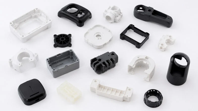
Molding draws on a broad range of production thermoplastics. Common workhorses include ABS, polypropylene, polycarbonate, nylon, POM, PEEK and elastomers such as TPU, and the material you qualify is the same material the production tool will run for the life of the program.
Printing is limited to the filaments and resins each machine family supports. A common FDM set is PLA, ABS, PETG, nylon and flexible TPU or TPE; SLA uses a separate and more limited set of photopolymer resins, which tend to be more brittle than FDM thermoplastics. Powder-bed processes such as SLS and MJF are largely tied to PA12 and a smaller family of filled or specialty powders.
The practical consequence is simple: confirm the production resin is available in your chosen process before committing to either route. A prototype printed in a convenient resin proves geometry, not the material your product will ship in. If the final part must meet a specific flammability, chemical-resistance or biocompatibility requirement, that requirement has to be qualified on the production material and process.
Material choice also feeds back into molding economics. Different resins cool at different rates, and cooling dominates cycle time, so a material change late in the program can move unit cost. One common design lever is to add ribs rather than thicken walls: ribs raise stiffness while keeping wall sections thin, which shortens cooling and reduces sink risk (cycle time and material).
Lead Time and Design Changes: How Fast, and How Costly to Revise?
Printing’s advantage here is straightforward: a first part arrives in hours to a few days, with no tooling step in between. That makes printing the natural place to iterate. A design change is a file edit and a reprint, and the cost of being wrong is measured in hours and a small amount of material.
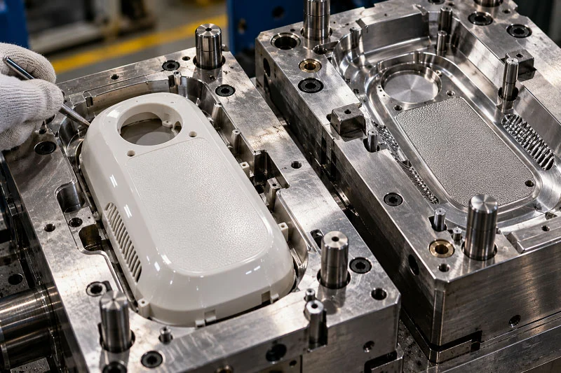
Molding requires mold design and build before the first shot — typically several weeks, depending on part complexity. That lead time is the price of the tool, and it is paid once.
Revisions are where the two routes diverge most sharply. Published figures put a mold modification at roughly €500–€3,000, with complex revisions pushing timelines back by weeks (molding FAQ). Steel grade matters too: some high-hardness grades have poor weldability, which complicates later alterations. On soft aluminum tooling, adding metal is difficult enough that oversizing areas likely to need adjustment is good practice from the start.
The conclusion follows directly. Design review before tooling starts pays for itself, because catching an issue on a drawing is far cheaper than catching it after the mold exists. Printing is where unresolved questions should be settled — fit, form, function, assembly interference, ergonomics — so that the tool is cut once, against a design that is already final.
Geometry and Strength: What Can Each Process Make?
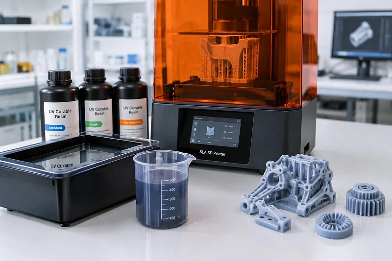
Molding handles complex three-dimensional shapes in a single shot, but it imposes design-for-manufacturing rules. Walls need draft so the part releases from the cavity. Wall thickness must be controlled to avoid sink and warpage. Gate location and cooling placement determine both cosmetic quality and cycle time. Side actions — pulls that form undercuts — add cost and constrain cavity layout: pulls on two opposite sides restrict the mold to a single row of cavities, on two adjacent sides to a 2 × 2 layout, and on all four sides to a single cavity.
Printing handles geometry that molding cannot produce without assembly: internal channels, lattices, captured features and hollow sections. That freedom comes with a mechanical caveat. Layer-by-layer construction produces anisotropy, and published work describes tensile strength in the build direction falling to a fraction of in-plane strength, with 50–75% reductions common (Additive Manufacturing, 2019). Flat FDM ABS has been reported at about 60% of molded tensile strength.
For a load-bearing part, that means orientation is a design decision, not a printer setting. A bracket printed so that its principal load runs in-plane behaves very differently from the same bracket printed upright. Where a printed part must carry real load, consider orienting the build to put tensile stress in-plane, thickening sections that see peel or cleavage, or adding machining stock on critical interfaces. Where the part must hit production-grade strength consistently, molding is the more direct answer.
When a Hybrid Print-Validate-Then-Mold Workflow Makes Sense
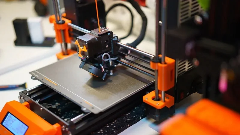
The sequence that de-risks most programs is print, validate, then mold. Print functional prototypes to prove fit, form and function; iterate the file while changes are still cheap; commit to tooling once the design is stable and the volume justifies it.
That sequence is the right call when:
- You need a testable part on a tight timeline. Printing puts a real part in hand in days, before a mold could even be designed.
- Design questions remain open. Every unresolved question is cheaper to answer in print than in steel.
- The tooling investment needs de-risking. A production volume that is plausible but not yet confirmed benefits from proving the design and the market before committing to a mold.
It is unnecessary when the design is fully mature and the volume is confirmed — in that case, going straight to tooling saves a step. And it may never be relevant when the requirement is genuinely low-volume, one-off or highly customized: a mold may never pay off, and printing or soft tooling remains the sensible route for the life of the product.
The two processes are partners rather than rivals. Printing proves the design while it is still tool-free; molding produces it at low unit cost once the design is final.
Verdict: Which Process Fits Your Project?
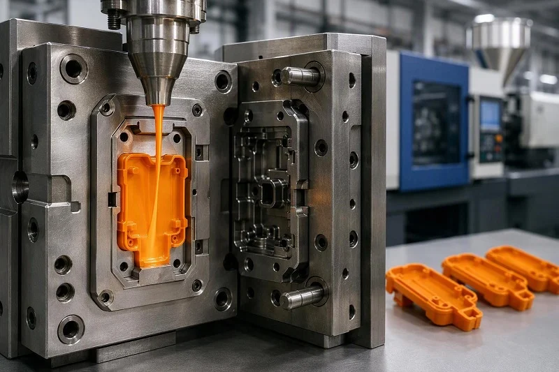
Printing wins on speed to first part, design flexibility and low upfront commitment — it is the right route for prototypes, functional tests, low-volume runs and any design that is still moving. Molding wins on per-part cost at volume, production-grade strength, finish consistency and material breadth — it is the right route once the design is final and the annual volume can carry the tool.
The decision rule in one sentence: print until the design is proven and the volume is confirmed, then mold — and calculate your own break-even rather than borrowing someone else’s number.
Choosing NOBLE to Support Your Injection Molding and 3D Printing Projects
NOBLE is a distinguished Chinese contract manufacturer, and our service capability and machining expertise are built to help clients move efficiently from prototyping through volume production. Whether your project belongs in a mold, in a printer, or in both in sequence, our team can support the decision and the execution.
Our quality credentials are central to that support. NOBLE is certified to ISO 9001:2015 and ISO 13485:2016, so quality management is embedded in how we plan, produce and inspect work rather than added at the end.
We offer a full scope of service from design to assembly — not production alone. That means support across the whole path a part takes: design input and manufacturability review, prototyping, tooling and production, and the assembly steps that turn parts into a finished product. For clients weighing injection molding against 3D printing, that breadth matters, because the right answer often changes as a program matures — and having one partner across prototyping and batch production keeps the transition from print to mold coherent.
Our capabilities are in-house, our inspection equipment and quality control system are set up to check parts against strict tolerance criteria, and our engineers work with a wide range of metal and plastic materials. If you are evaluating a part and want to know which route fits your volume, tolerance and timeline, send us the design and requirements — we will help you compare the paths and move forward efficiently.
FAQs about Injection Molding vs 3D Printing
Is one process simply better than the other?
No. Printing wins on speed to first part, design flexibility and low upfront commitment. Molding wins on per-part cost at volume, production-grade strength, finish consistency and material breadth. The right choice depends on your volume, your tolerance requirements and how settled your design is.
Can a design move from printing to molding?
Yes, and that is the most common path. Printing validates fit, form and function while changes are cheap; molding takes over once the design is stable and volume justifies tooling. Expect to revisit draft angles, wall thickness, gate placement and material shrinkage before the mold is cut.
Can the two processes be combined?
They can. Printed prototypes, printed jigs and fixtures, and printed bridge parts can support a molded production program. Printed inserts can also be overmolded in some designs, though that requires specific engineering review.
Which route suits medical or regulated parts?
Both can serve regulated work, but the qualification burden differs. Molding offers material and process consistency across a production run; printing offers speed and customization, with published studies showing high dimensional accuracy in controlled medical contexts. In either case, the production material and process — not the prototype — must be qualified, and the applicable quality system requirements apply.
Does one process become obsolete as volumes change?
No. Each remains relevant in its own range. Printing stays useful for prototypes, low-volume runs, spare parts and design iteration even in a program that molds at volume; molding remains the economic choice once annual volume is high enough to amortize the tool.