In 2026, making robots depends on CNC machining, injection molding, 3D printing, casting, sheet metal work, and plastic welding. These use materials like aluminum alloys, high-strength steel, titanium, carbon fiber composites, engineering elastomers, and smart materials. Choosing smart robot components is now a system-level decision. It is driven by payload, heat, and duty-cycle needs. Making a robot too small for its payload limit causes faster joint wear and lower speed. So frame size and materials must include a 20–30% safety margin. Heat management controls conductor shape and enclosure cooling. Duty-cycle profiles require retention hardware and board stiffness. This guide links these processes to specific part types—bases, bodies, arms, and gearboxes—with trade-offs and paths to scale up.
Machining Processes for Smart Robot Components
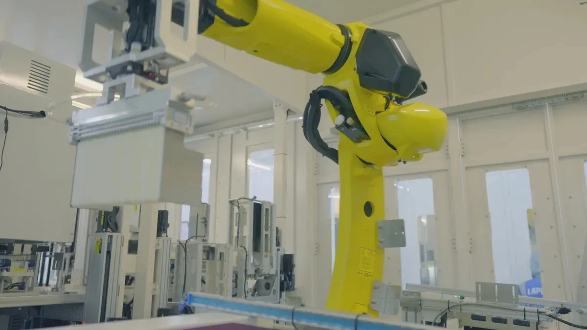
Choosing the best way to make robot parts depends on three things: the shape of the part, how many you need, and how exact it must be. The shape of the part decides if you can cut it from a block or if you need a mold. The number of parts tells you if paying for a steel tool is worth it. Tolerance needs tell you if a net-shape process works or if you need extra machining. These three factors work together. A set of smart robot components like an actuator housing needs tight tolerances for bearings, so CNC machining is often the best choice. A sensor housing you need ten thousand of points toward injection molding. A complex gripper prototype with internal channels? That is where 3D printing shines.
CNC Machining for Smart Robot Components
CNC machining is the go‑to process for parts that need high accuracy. Joint bodies, gearbox housings, and bearing seats all fit here. These parts must line up with very little play over thousands of cycles.
Tolerances and Surface Finish
General milling holds ±0.01 mm. Precision turning and five‑axis work can push that to ±0.005 mm or tighter. That level of accuracy matters when a robot arm repeats its motion without drift. Surface finish matters just as much. Bearing seats and seal faces need a roughness of Ra 0.4–0.8 μm. Bearing seat roundness stays within 0.005 mm. After machining, you can add surface treatments. Hard anodizing (Type III) adds 25–50 μm of protection. Micro‑arc oxidation (MAO) goes thicker at 50–100 μm. These coatings help aluminum parts resist wear in high‑cycle robotics applications.
Best‑Fit Metals and Plastics
Aluminum alloys are common for structural robot parts. They are light, strong, and machine well. Stainless steel works when corrosion resistance matters. For plastics, machined PEEK and acetal (POM) appear in bushings and wear pads. The key is matching material to load pa th. For these applications, manufacturing partners with CNC machining expertise are essential. Their team knows what tolerances robot components need and handles both prototyping and mass production.
Injection Molding for Smart Robot Components
When production volume climbs past a few thousand parts, injection molding becomes the economical choice. The upfront tooling cost is higher, but the per‑part price drops fast.
Tooling Lead Times and Cost
Here is the typical breakdown for robot sensor housing molds:
| Tooling Type | Typical Cost Range | Typical Lead Time | Best Suited For | Mold Life |
| Aluminum prototype molds | $2,000–$8,000 | 2–3 weeks | Design validation, low volume (100–10,000 parts) | 1,000–10,000 shots |
| Steel production molds | $5,000–$50,000+ | 4–6 weeks | High volume (10,000–1,000,000+ parts) | 100,000–1,000,000+ shots |
Per‑part costs run from $0.50 to $50 depending on material and cycle time. Shipping to North America and Europe adds 3–5 days. Express shipping cuts that to 2–3 days. So if you need ten thousand sensor covers, injection molding makes sense. If you need ten, CNC or 3D printing is a better path.
Overmolding for Sensor Interfaces
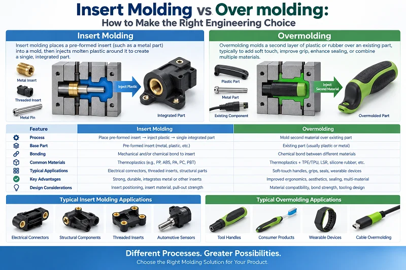
Injection molding also lets you combine materials in one part. Overmolding places a soft elastomer over a rigid plastic core. This creates integrated seals, vibration dampeners, or grip surfaces. For sensor housings, overmolding can embed a silicone gasket directly into the part. That eliminates a separate assembly step and improves sealing reliability. It is a smart manufacturing for robotics trick that reduces part count and assembly time.
Additive Manufacturing for Smart Robot Components
Additive manufacturing, or 3D printing, handles shapes no other process can. But it comes with real trade‑offs in speed and finish.
Metal vs. Polymer Printing
Here is how the two compare for robot parts:
| Aspect | Metal 3D Printing |
| Complex geometries | Ideal for complex, lightweight parts with internal channels that machining cannot create |
| Waste | Less than 5% waste versus up to 90% for CNC |
| Speed | Build times are much longer than traditional methods |
| Cost | High per‑part cost; not driven by geometry complexity |
| Surface finish | Poor as‑printed; most parts need post‑machining |
| Build size | Typically ~250 x 250 x 300 mm; large machines ~400 x 400 x 380 mm |
| Material availability | Very limited number of printable metals |
For polymer 3D printing, thermoplastics like PEEK and ULTEM handle demanding industrial environments. Metal‑polymer composites combine strength with light weight. The choice comes down to end‑use requirements. Metal printing works for structural brackets with conformal cooling channels. Polymer 3D printing works for grippers and custom end‑of‑arm tooling. This technology enables geometry that subtractive methods cannot reach.
Lattice and Conformal Cooling
One big advantage of 3D printing is lattice structures. These open frameworks reduce weight while keeping stiffness. For robot arms and end effectors, that means faster acceleration and lower energy use. Conformal cooling channels are another win. In injection molding, these channels follow the part shape to remove heat evenly. That cuts cycle times and improves part quality. For smart robot components, the same technology applies to any part that generates heat. You can print cooling paths directly into actuator housings or motor mounts. This additive manufacturing approach is changing how engineers think about thermal management.
| Process | Geometry Complexity | Volume Suitability | Tolerance |
| CNC Machining | High but limited internal features | Low to medium (low tooling, medium per‑part) | Very high |
| Injection Molding | Moderate (needs draft angles) | High (high tooling, low per‑part) | High |
| 3D Printing | Very high (complex internal) | Very low (no tooling, high per‑part) | Low to medium |
All three manufacturing processes have a role in modern robotics manufacturing. Knowing when each one fits is the real skill. CNC for precision structural parts. Injection molding for volume production of enclosures. 3D printing for prototypes and complex geometries. Many manufacturing robot parts use a mix of these processes across different parts of the same robot.
For anyone building robots, mastering these manufacturing processes is essential. The right manufacturing choice saves time, money, and rework. For high‑volume needs, robotics manufacturing partners with injection molding expertise become critical. And 3D printing rounds out the toolkit for rapid iteration and complex geometries.
Casting and Forming for Manufacturing Smart Robot Parts
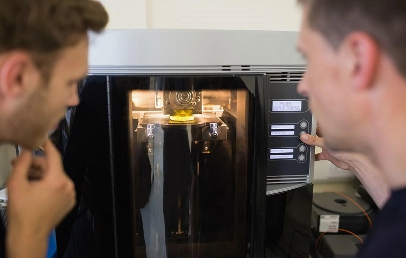
When you need thousands of robot frames, casting and forming work better than cutting methods. Cutting a complex shape from a solid block turns most of the material into chips. Casting puts material only where you need it.
For structural components at medium-to-high volumes, fabrication is faster and costs less. Stamping becomes very economical at higher volumes.
Die Casting for Structural Smart Robot Components
Die casting keeps the cost per unit low for high-volume metal parts. Tooling costs are significant, but cycle times stay fast. This works well for robot bases, motor housings, and structural brackets in robotics manufacturing.
| Volume Range | Stage |
| Prototyping | 3D Printing, CNC |
| — | — |
| Low-Volume | CNC, Sheet Metal |
| Mid-Volume | Die Casting, Sheet Metal |
| High-Volume | Die Casting, Stamping |
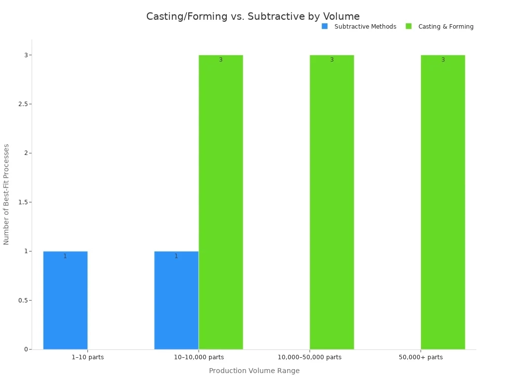
Plan your manufacturing processes around volume targets.
Aluminum and Magnesium Alloys
Aluminum alloys that flow well into thin wall sections are used, keeping cycle times short. Magnesium alloys are lighter than aluminum. For robot arms, weight savings in the base structure matter. Magnesium costs more and needs special handling during melting.
Porosity Control and Post-Machining
Porosity is the main challenge in die casting. Gas pockets can weaken parts or cause leaks. Design and process methods help mitigate it. For smart robot components like actuator housings, porosity control is critical. Keep sealing faces away from late-fill regions.
Investment Casting for Intricate Smart Robot Components
Investment casting uses a wax pattern. The wax melts out. Metal fills the cavity. The result is a near-net-shape part.
Stainless Steel and Superalloys
This process works with stainless steel and superalloys. These suit robot components in high-heat applications or corrosive environments. The process forms internal passages machining cannot reach. This technology expands design options.
Casting vs. CNC Machining
For small volumes, CNC wins. For complex shapes, casting reduces machining time. Cast the bulk shape. Machine critical surfaces only. This hybrid approach balances cost and accuracy in manufacturing for robotics.
Sheet Metal Fabrication for Smart Robot Components
Sheet metal works for enclosures, frames, and brackets. It provides good structural integrity with repeatable quality. It becomes economical at higher volumes. Metals include stainless steel, aluminum, titanium, and copper. Various thicknesses are available.
Frames, Brackets, and Mounting Plates
Laser cutting creates blanks. Press brakes bend them. Welding joins the pieces. Laser cutting provides tight tolerances. Bending holds acceptable tolerances. These manufacturing processes work well for manufacturing robot parts.
Laser Cutting, Bending, and Welding
Laser cutting handles complex profiles. CNC press brakes ensure consistent angles. Robotic welding delivers repeatable quality. For high volumes, progressive die stamping takes over. Cycle times drop to seconds. Per-part costs become very low. This technology suits high-volume applications.
Blow molding and plastic welding are complementary manufacturing robot parts processes. They work for plastic frames and enclosures. Both improve consistency in high-volume robotics manufacturing.
Matching Processes to Smart Robot Components
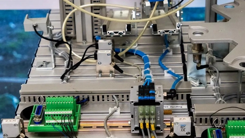
Now let’s connect each process to a specific part on the robot. Picking a process for smart robot components means thinking about how robot components fit together. A humanoid robot squeezes machined frames, bearings, sensors, and cables into a small space. Every process choice changes how easily it all fits.
Actuators and Joints
Actuators and joints carry the load and create motion. The housing and gearbox must handle repeated stress without wearing out too much.
Housing and Gearbox Manufacturing
Die casting works well for motor housings in high volume. It makes thin walls fast. But the gear teeth inside need precise cutting after casting. CNC hobbing shapes the teeth to the required profile. For smaller runs, a machined block of aluminum is common. Manufacturing processes like die casting and CNC machining are both used here.
Surfaces that hold seals must be smooth. That means post-machining after casting. The result is a strong, reliable housing. This approach balances manufacturing processes for the component’s role in manufacturing robot parts.
Bearing and Shaft Tolerances
Bearings and shafts need extreme precision for a robot arm. Bearing journals require a tolerance of ±0.005 mm. Total runout must be minimized, especially for high-precision servo applications. Surface finish is Ra 0.4 µm to 0.8 µm for journals.
Case Example: Robotic Joint Housing Project
A robotic joint housing for an industrial automation system contained multiple bearing interfaces. The material was Aluminum 7075-T6. The tolerance requirement was ±0.005 mm. Production quantity was about 2,000 pcs annually. The critical requirement was concentricity between dual bearing seats. Dedicated fixtures were developed to reduce repositioning error. Critical features were machined in a single setup. Final dimensions were verified via CMM inspection.
Result: A more predictable manufacturing process with improved dimensional consistency. Process stability created more value than reducing cycle time.
The right machining approach for a robot arm prevents scrap. CNC turning with a single setup is vital. For miniature shafts, Swiss-type machining supports the workpiece to prevent deflection. Precision grinding is mandatory for bearing journals to reach tight tolerances. Turning alone cannot hold tighter than ±0.01 mm. This is typical for robotic components. These methods are common in robotics manufacturing for precision applications.
Sensor Housings and Enclosures
Sensors need protection from electromagnetic interference (EMI) and heat. The housing must also seal against dust and moisture.
EMI Shielding and Sealing
Overmolding places a conductive gasket directly into the housing. This creates a reliable seal against EMI. Several materials achieve high shielding, as shown in the chart below.
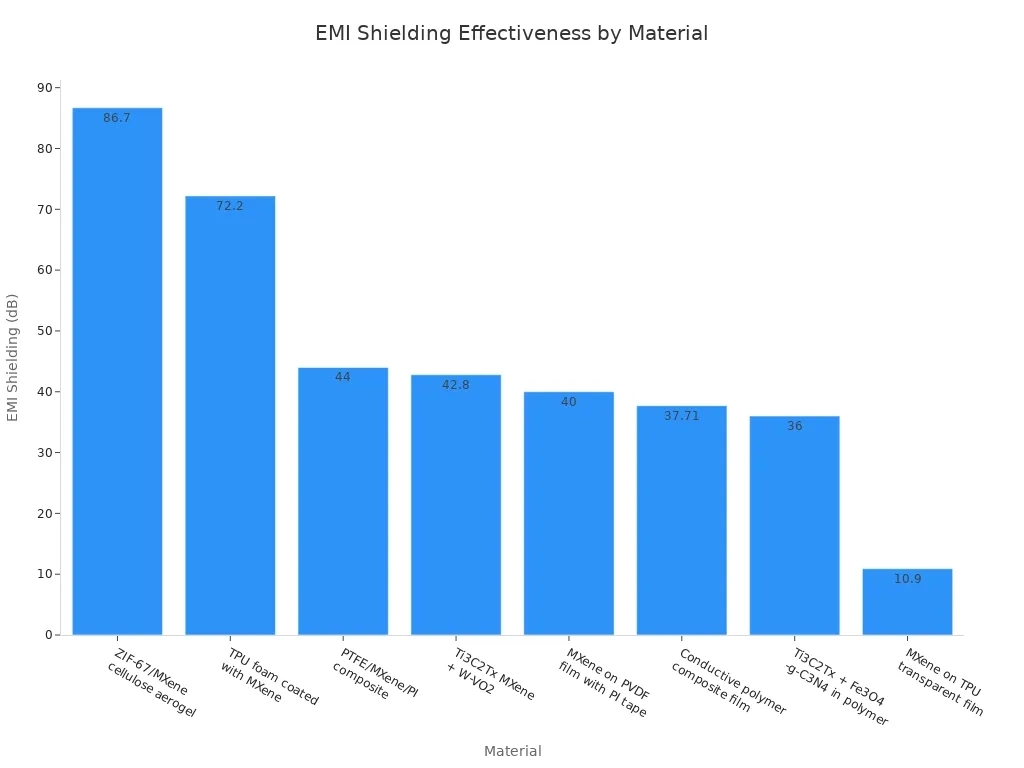
For robotic sensor housings, injection molding with a conductive filler works well. The process embeds the shielding into the part itself. No secondary operation is needed. This saves time and ensures consistent coverage. This technology is useful for a wide range of applications.
Thermal Management Features
Heat inside an enclosure can shift sensor readings. The housing must draw heat away from electronics. Materials with high thermal conductivity help.
3D printing allows conformal cooling channels inside the housing. These channels follow the shape of the part to remove heat evenly. This technology keeps sensor boards operating at a stable temperature. For metal enclosures, CNC machining can add fins to increase surface area.
Frames, Chassis, and End Effectors
Frames provide the structural backbone. End effectors interact with the world. Stiffness and weight must be balanced carefully.
Stiffness-to-Weight Priorities
For a robot arm, steel at the base provides high stiffness. Aluminum in the mid-sections balances support with reduced weight. Composites or plastics at the end effectors minimize mass to reduce inertial loads on motors.
Carbon fiber composites enable anisotropic properties. Stiffness can be placed exactly where needed. This material is used in high-speed Delta robots and drone arms. However, CFRP cannot be machined like metal. It requires molding or layering. When CNC machining is necessary, proper tooling prevents delamination. These manufacturing processes expand design possibilities.
Modular Mounting Interfaces
Frames often need standardized bolt patterns. CNC drilling creates these patterns with high accuracy. For high volume, stamping or injection molding can embed threaded inserts. This speeds up assembly and ensures repeatability.
End effectors benefit from modular designs. A single robot arm can swap grippers for different tasks. The mounting interface must be stiff but lightweight. Machined aluminum works well here. Proper process selection ensures alignment is maintained across all units. This is a key factor in manufacturing robot parts for modular systems, a common need in robotics manufacturing.
Metals for Smart Robot Components
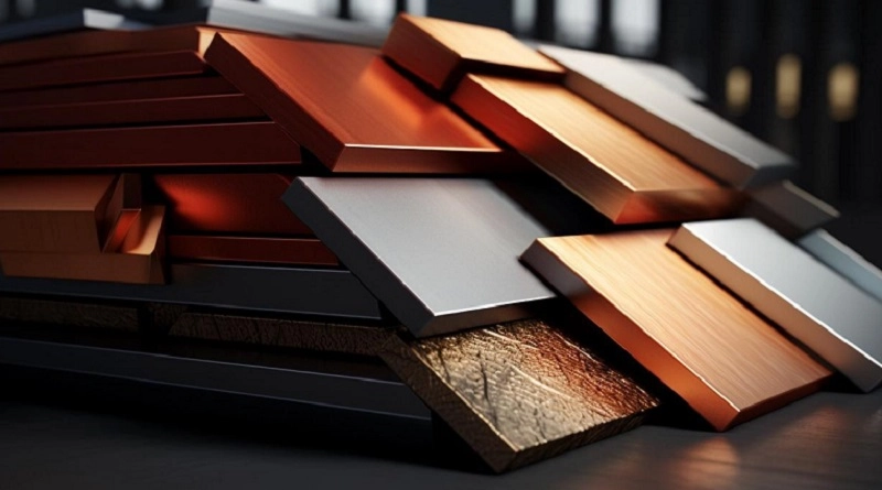
Traditional metals like steel and aluminum still form the backbone of most machines. But smart materials that change shape are becoming important too. For structural parts that carry loads, you need something rigid and predictable. That is where metals come in. The choice depends on the load path, exposure to moisture, and its machinability. Here is how to pick the right metal for your manufacturing robot parts.
Aluminum Alloys
Aluminum keeps robot parts light and cost-effective. Three grades stand out for smart robot components: 6061, 7075, and 2024.
6061 vs. 7075 vs. 2024
Each aluminum alloy fills a specific role:
- 7075-T6: Highest tensile strength and excellent strength-to-weight ratio. Perfect for high-load components like joint housings and arm segments. Not weldable, and corrosion resistance is lower. Tends to crack if you weld it.
- 2024: Superior fatigue resistance. Great for cyclic loading in robot arms that move back and forth all day. Needs coating or cladding because corrosion resistance is poor.
- 6061: Balanced strength, good machinability, and easy to weld. Corrosion resistance is excellent. Cost is low. Works for general structural use, brackets, and enclosures.
For a high-load joint in a robot arm, you might use 7075. For a part that flexes constantly, go with 2024. For a mounting bracket that does not see much stress, 6061 is enough.
Anodizing and Surface Treatments
Aluminum alloys are soft without surface treatment. Anodizing adds a protective oxide layer. The anodizing type changes how the part performs:
| Anodizing Type | Oxide Layer Thickness | Corrosion Resistance | Wear Resistance | Fatigue Strength Impact | Best Applications |
| Type I (Chromic) | Thin | Good | Low | Minimal | Fatigue‑critical aircraft parts |
| Type II (Sulfuric) | Moderate | Better | Moderate | Moderate | General purpose, decorative |
| Type III (Hard) | Thick | Best | Excellent | Significant | Wear surfaces, harsh environments |
Hard anodizing gives the best surface durability but reduces fatigue life the most. If your component experiences high cycle loading, balance wear resistance against fatigue. For a gearbox housing that sees repetitive stress, you might choose Type II over Type III to preserve fatigue life. For these applications, manufacturing partners with machining and anodizing expertise can help ensure the right surface treatment for each part.
Stainless Steel and Titanium
When aluminum is not strong enough, you step up to stainless steel or titanium.
Corrosion and Strength Requirements
Stainless steel provides high strength and excellent corrosion resistance. It is ideal for ground-based chassis, heavy-duty base plates, and protective armor where weight is less critical. Titanium offers higher specific strength and lower density than stainless steel, allowing weight savings. That means a titanium part can achieve the same structural integrity at a lower weight.
Choose titanium for high-speed robotic arm joints, slim-profile end effectors, and even internal gears (if coated with DLC or nitriding). Stainless steel is better for parts that see high friction, like gears and shafts, because titanium is prone to galling—sliding titanium surfaces can adhere and seize.
Machinability and Cost Considerations
Titanium machining is expensive. Blank costs are higher. Low thermal conductivity keeps heat at the cutting edge, causing faster tool wear. The material’s gummy nature requires specialized high-torque equipment and slower feed rates. That increases total machining time and cost. Stainless steel is easier to machine and costs less per pound.
So the decision balances weight savings against cost. If weight reduction is critical for your structure, titanium is worth the premium. For cost-sensitive or heavy structural uses, stainless steel wins.
From a practical perspective, material selection should follow the load path. High-stress, fatigue-prone joints in a robot arm benefit from titanium’s strength-to-weight ratio. Frame parts that do not see cyclic loading can use stainless steel or aluminum.
Carbon Fiber Composites
Layup and Resin Transfer Molding
Carbon fiber composites are not metals, but they are crucial for building lightweight robot structures. Layup is the traditional method. You stack layers of prepreg fabric in a mold. Each layer is oriented to carry load in a specific direction. Then you cure the part in an autoclave under heat and pressure. Resin transfer molding (RTM) uses a dry fiber preform placed in a closed mold. Resin is injected under pressure. This technology allows complex shapes with good fiber alignment.
Both processes produce stiff, lightweight parts. For a high-speed Delta arm, carbon fiber cuts inertia significantly compared to aluminum.
Metal-to-Composite Joining
Joining metal to composite is the big challenge. Adhesive bonding works well. Mechanical fasteners can tear the composite if not designed properly. Thick composite laminates allow threaded inserts, but you need careful stress analysis. Another technique involves co-curing metal inserts into the composite during molding. This embeds the metal part directly into the composite structure, creating a strong bond without drilling holes.
For hybrid parts, you might use a metal bracket bonded to a composite arm. This combines the stiffness of metal at the joint with the light weight of the composite along the arm.
The right material for each part depends on load path, environment, and how you plan to machine it. Aluminum for light structural parts. Steel and titanium for high-stress areas. Composite for extreme weight reduction. Each material brings trade-offs that must match the application. This technology is vital for modern robotics, enabling lighter and faster robots. The correct material selection ensures durability and performance across diverse applications.
Polymers and Smart Materials for Smart Robot Components
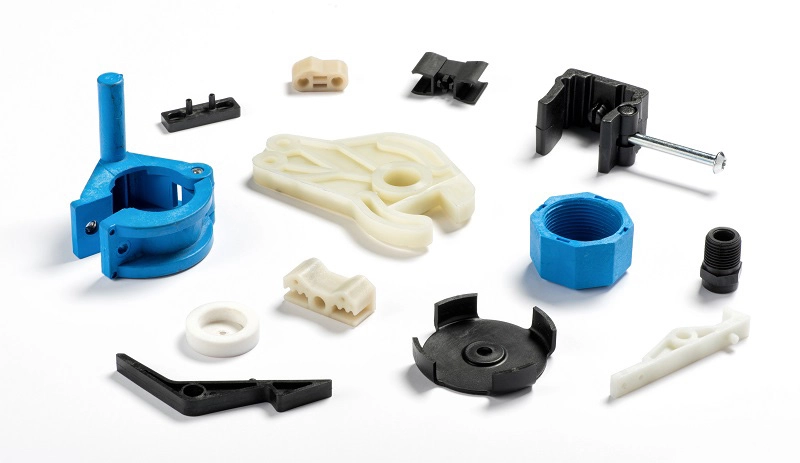
Polymers act in many different ways. Some work like strong structural parts. Others bend, seal, or sense things. You can think of them as a range. On one end are stiff engineering plastics. On the other end are smart materials that change shape when told to. Picking the right one begins with the job the part must do.
Engineering Plastics
PEEK, POM, and Nylon Applications
PEEK stands up to tough conditions. It fights off chemicals and heat, so it works in sterile or corrosive places. POM, also known as Delrin, is great in low-friction spots like bushings and wear pads. Nylon adds toughness and impact resistance for less money. For making robot parts, these three cover most wear and structural needs.
Wear Resistance and Lubricity
Wear resistance and lubricity often matter more than plain strength. A gear that rubs against metal will break down fast without a low-friction surface. POM lubricates itself well. PEEK holds up when load and heat come together. Choosing a material here is about sliding contact, not static load.
Elastomers
Silicone and TPU for Grippers and Seals
Silicone stays flexible across a wide temperature range. It works well for seals and soft gripper pads. TPU gives higher tear strength and abrasion resistance. Robot grippers often use TPU when they must grab rough or sharp objects. Both materials show up in soft robotic uses where a gentle touch matters.
Shore Hardness Selection
Shore hardness tells you how soft or firm an elastomer feels. The A scale covers softer rubbers. The D scale covers harder ones. A soft gripper pad needs a low Shore A value. A firm seal needs a higher one. Match the number to the contact force and the part being handled.
Smart Materials
Shape Memory Alloys and Piezoelectrics
Smart materials can change shape. That opens up actuator and gripper designs beyond rigid limits. Shape memory alloys go back to a set shape when heated. Piezoelectrics move a tiny, exact amount when voltage is applied. Both allow compact motion without a bulky motor.
Embedded Sensing and Self-Healing Polymers
Some polymers carry sensing or healing ability inside them. Embedded sensing lets a robot feel contact or strain right in the part. Self-healing polymers fix small cracks on their own. It is worth noting that this technology is still growing. From a practical view, these materials suit robotics platforms that need lighter, adaptive components.
Design Considerations for Smart Robot Components
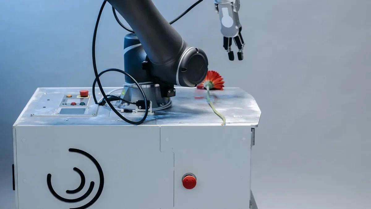
Design choices and process choices go hand in hand. You can’t pick a material first and then look for a machine that can handle it. That order leads to rework. Smart robot components need both decisions made together, early in robot design.
Precision and Tolerance Stack-Up
Datum Strategy and GD&T
Every tolerance starts with a datum. Choose one main face and build all dimensions from it. This keeps stack-up small across a joint assembly. GD&T then tells the machinist what really matters. A position callout on a bearing bore beats a pile of plus-minus numbers. It also gives inspection a clear pass or fail rule.
Metrology and Inspection Planning
Plan how you’ll measure a part before you cut it. CMM checks work for critical bores and faces. Optical metrology suits thin walls and complex profiles. For manufacturing robot parts, inspection planning is part of precision engineering, not an afterthought. Manufacturing partners can help clients move from prototyping to mass production of smart robot components without losing tolerance control.
Weight Reduction
Topology Optimization and Generative Design
Topology optimization is physics-based and works best early in robot design. Generative design is rule-based and focuses on how the final part should look. A hybrid approach blends both. The payoff is real:
- Weight reductions are common compared to conventionally designed end effectors.
- Generative design has produced grippers with significant weight savings in automotive assembly.
- Topology-optimized vacuum gripper bodies have achieved substantial weight reduction with better stiffness than solid bodies.
Manufacturing constraints get defined upfront. A billet-machined end effector limits the algorithm to 3-axis or 5-axis CNC geometry. A printed part adds rules for wall thickness and overhang angles.
Topology optimization software can generate a drone model with good performance.
Material Substitution Trade-Offs
Swapping steel for aluminum saves weight but changes stiffness. Swapping aluminum for carbon fiber saves more, yet joining becomes harder. Each swap shifts the load path. Test the new design under real duty cycles before you commit.
Durability and Environmental Resistance
Wear, Fatigue, and Impact Loads
Joints face millions of cycles. Standards cover rotational durability for joint mechanisms, temperature cycling, and vibration resistance. These standards give robot design a durability baseline instead of guesswork.
IP Ratings, Coatings, and Seals
IEC 60529 sets ingress protection levels. Pick the rating that matches the environment.
Coatings and seals extend service life. HNBR suits joint seals with PAO/ester oils. PTFE-lipped seals with FKM backing cut friction in precision joints. Peroxide-cured EPDM handles outdoor UV exposure. These choices matter for harsh-environment applications, and they show how design for manufacturability and design for durability overlap. This technology keeps robot platforms running longer in demanding applications.
Quality Control for High-Quality Robot Parts
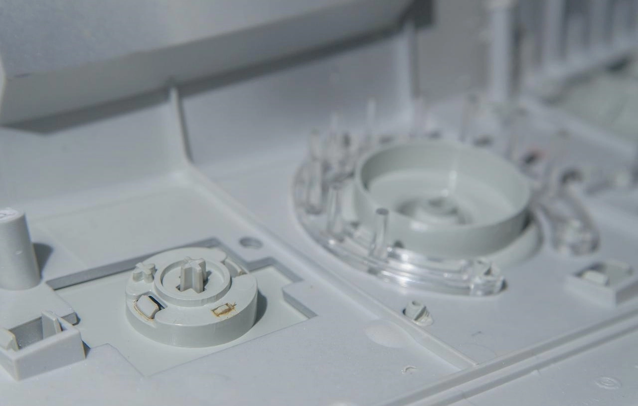
Here is how quality control works for robot parts. A high-quality robot part meets three standards. First, its measurements match the drawing exactly. Second, you can trace every measurement back to a certified standard. Third, every part in a batch is the same as the last one. Those three things — dimensional conformance, traceability, and repeatability — are what quality control protects.
In-Process Inspection
CMM and Optical Metrology
Coordinate measuring machines are the standard tool for checking sizes and shapes. A CMM touches the workpiece with a probe at programmed points. Then it figures out flatness, roundness, true position, and perpendicularity in three dimensions. With high volumetric accuracy, the CMM can catch problems handheld tools would miss. Rooms kept at controlled temperatures are normal for these machines to reduce errors from heat expansion.
Repeatability and reproducibility are not the same thing. Repeatability means the same operator gets the same result with the same instrument. Reproducibility means different operators get the same result with the same instrument. Both matter when many people handle inspection on a production line. Good repeatability with poor reproducibility points to a training issue, not a machine problem.
Traceability and Documentation
Documentation backs every batch. Measurement records are serialized and tied to certified master blocks. Automated inspection plans pull measurements from scanned point clouds with the same control as contact probing. These plans meet quality management requirements. They also give customers a clear audit trail.
Some benefits of automated inspection plans include:
- Consistent measurement data across different suppliers
- Technicians with little training can run inspections quickly
- The digital thread and model-based definition stay intact
- Process control removes doubt about product compliance
Scaling Production
Prototype-to-Production Transitions
Moving to production changes how you think about tooling. Prototype tooling is fast and flexible. Production tooling must be durable and easy to maintain over a long run. That affects steel selection, cooling design, wear surfaces, and venting. Poor cooling increases cycle time and causes dimensional variation. Weak venting creates burns or short shots.
Material selection gets stricter at scale. You need tighter control of resin grade, moisture, drying conditions, and lot traceability. Uncontrolled variation in these factors affects shrinkage, warpage, and assembly fit. Tolerances also need a reality check. A tolerance that worked on a prototype might not hold in production, leading to scrap.
Tooling and Supply Chain Planning
Inspection strategy changes with volume. First-article inspection, in-process checks, automated vision inspection, and SPC for critical features all become part of the plan. Automation helps too. Robotic part removal and conveyors reduce scratches and contamination from manual handling.
Secondary operations need early planning. A molded part might need ultrasonic welding, laser marking, painting, or bonding. If you wait until tooling is cut to plan these steps, the cost goes up. Validation also becomes central. Tool trials, dimensional reports, and PPAP evidence are required before steady production can start.
Cost Drivers
Material, Labor, and Tooling Costs
Three factors drive the cost of high-quality robot parts. Material cost depends on grade and volume. Labor cost depends on cycle time and automation level. Tooling cost depends on mold complexity and expected life. For injection molding, steel molds can cost $5,000 to $50,000 depending on complexity. At low volumes, the per-part price is higher because setup costs spread over fewer units. A partner with Design for Supply Chain expertise can spot cost problems early and reduce the risk of expensive redesigns later.
Volume Discounting and Lead Times
Volume changes everything about pricing. At higher volumes, the per-part cost drops a lot compared to low volumes. Lead times shift too. Low-volume runs ship in weeks. High-volume production runs on a repeat schedule and needs longer lead times for mold making and material sourcing. A partner who can scale production adds flexibility to the supply chain.
Future Trends in Smart Robot Components

The trends shaping smart robot components in 2026 are practical, not just ideas. They change how you plan capacity, pick materials, and price a job.
Automation and AI in Production
Lights-Out Machining Cells
Unmanned production is already happening. Many companies use large numbers of robots in automated cells that machine, assemble, paint, and inspect. They can work for extended periods without human help. This cuts assembly time and removes defects significantly.
The payoff is easy to measure. Direct labor drops considerably, output rises substantially, and defects fall. Payback periods vary by industry. For anyone making smart robot components, that math favors robotic automation at scale.
AI-Driven Process Optimization
AI now tunes machining settings in real time. Cycle times improve, throughput increases, and material costs fall through better yield. Predictive analytics also sharpen production planning, quality control, and supply chain forecasting. Machine vision catches defects that human inspectors miss. That matters when you are producing thousands of identical parts.
Sustainable Materials and Processes
Recycled Alloys and Bio-Based Polymers
Sustainability is moving from marketing to procurement. Manufacturers are adopting circular practices, green energy, and carbon-neutral initiatives. Recycled aluminum and bio-based polymers are entering the supply chain, though qualification still takes work. From a practical view, ask your supplier for lot traceability on recycled stock before you design it into a load-bearing part.
Energy-Efficient Manufacturing
Energy use drops in optimized cells. Part of this comes from smarter equipment operation. Part comes from eliminating lighting and HVAC in unmanned areas. AI-driven efficiency optimization supports this directly. For smart robot components, energy per part becomes a real cost line, not an afterthought.
Emerging Fabrication Methods
Multi-Material Additive Manufacturing
Printing metal and polymer in one build is maturing fast. This lets you place a rigid core inside a soft gripper pad without assembly. Additive manufacturing already handles internal channels and lattices that subtractive methods cannot reach. Multi-material builds extend that advantage to hybrid parts.
Micro-Fabrication for Miniature Robots
Miniature robots need tiny joints, sensors, and gears. Micro-fabrication borrows techniques from electronics manufacturing to produce these at scale. The same workflows used for full-size parts are being adapted for micro-scale production. Expect this to unlock new applications in medical and inspection robots.
Choose NOBLE for Smart Robot Components Manufacturing
NOBLE focuses on metal and plastic processing of smart robot components manufacturing. We handles all the work this guide has talked about. This includes tight-tolerance machining, molded housings, and cast structural parts. If you are getting parts for a robot platform, you work with NOBLE instead of five vendors.
Metal and Plastic Processing Expertise
CNC Machining, Molding, and Casting
NOBLE does CNC machining for parts that need tight tolerances, like joint housings and bearing seats. We also does injection molding for enclosures and sensor covers at high volume. Casting covers larger structural pieces where cutting from a block wastes material. You can move a single part across all three processes as your volume grows.
Material Selection Support
Picking the right metal or polymer is half the battle. NOBLE helps you match material to load path, corrosion exposure, and machinability. We will tell you when certain aluminum alloys make sense and when others are enough. That kind of guidance saves you from expensive redesigns later.
Certifications and Quality Standards
Quality Management
A robust quality management system backs NOBLE’s work. That means documented processes, traceable records, and repeatable results across batches. For buyers, it is proof that the shop runs on systems, not guesswork.
Precision and Compliance
Additional stricter layers for precision and compliance suit medical and high-reliability applications, where a failed part is not an option. It signals tight process control and strong documentation practices.
End-to-End Services
Design, Prototyping, and Assembly
NOBLE supports design for manufacturability reviews before tooling gets cut. Prototyping runs through CNC or 3D printing so you can test fit and function fast. Assembly services then bring the pieces together, which cuts handling time and keeps tolerances under one roof.
From Concept to Production
The path from concept to production stays with one partner. You start with a drawing, move through prototypes, and scale into molding or casting without switching suppliers. That continuity matters for custom manufacturing projects with tight timelines. It is worth noting that this full-range model fits robot programs that evolve quickly.
Process and material choices for smart robot components are interdependent. Decide them together, early in design. Match the process to your volume and geometry. Match the material to the load path and environment. Validate each critical dimension with inspection. That logic turns a component list into a working robot.
Audit your current smart robot components against this guide’s process-material matrix. Check each part. Did you pick the right process for this volume? The right material for this load?
Scalable, certified manufacturing partners will separate competitive robot platforms in 2026. NOBLE brings both process depth and material technology to every application. That technology is what makes modern robotics applications possible.
FAQs of Smart Robot Components
How do I pick between CNC machining and injection molding for smart robot components?
Start with how many parts you need and the shape. CNC is best for very exact sizes and for small runs. Injection molding saves money when you need more than a few thousand parts. A sensor housing at high volume works well with molding. An actuator housing that needs tight tolerances stays on a CNC machine.
What tolerance can I realistically hold on a robot joint housing?
Normal milling keeps sizes within ±0.01 mm. Five-axis and precision turning can go to ±0.005 mm. Bearing journals need that tighter range, plus roundness inside 0.005 mm. The surface smoothness for seal areas should be Ra 0.4–0.8 μm.
When does die casting beat machining for structural parts?
Die casting works well when you need high volume. The mold costs are significant, but each part is made quickly. Robot bases and motor housings are good choices. For fewer parts, cutting from aluminum costs less.
Which aluminum alloy should I choose for a high-load arm segment?
Aluminum 7075-T6 has the highest strength and a good strength-to-weight ratio. It works for high-stress joints and fast arm parts. Aluminum 6061 is fine for brackets and enclosures with lighter loads. Pick 2024 when resistance to repeated stress matters most.
How do I protect sensor housings from EMI and heat?
Overmolding puts a conductive rubber gasket right into the housing. That blocks interference without a second step. For heat, 3D printing adds cooling channels inside the part. Metal enclosures can get fins cut by CNC to help cool.
What does “high-quality robot parts” actually mean in practice?
Three things: sizes match the drawing, every measurement can be traced to a certified standard, and each batch of parts is the same as the last. CMM inspection catches tight tolerances that hand tools can’t detect.
How do I move from prototype to full production without losing tolerance control?
Plan the tooling, material, and inspection at the same time. Prototype tooling is fast but doesn’t last long. Production tooling needs better cooling and air vents. Lock in the plastic type, drying steps, and lot tracking before the first production run begins.
What certifications should I look for in a manufacturing partner?
Look for quality management certifications that cover documented and repeatable steps. Additional certifications for stricter precision are beneficial for high-reliability jobs. Together they show traceable records and tight control across batches.