1. What is Patient Transfer Robot CNC Machining
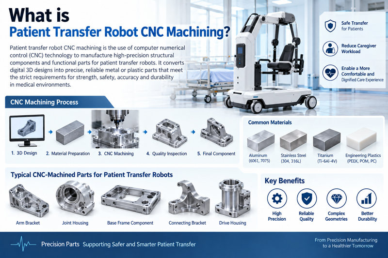
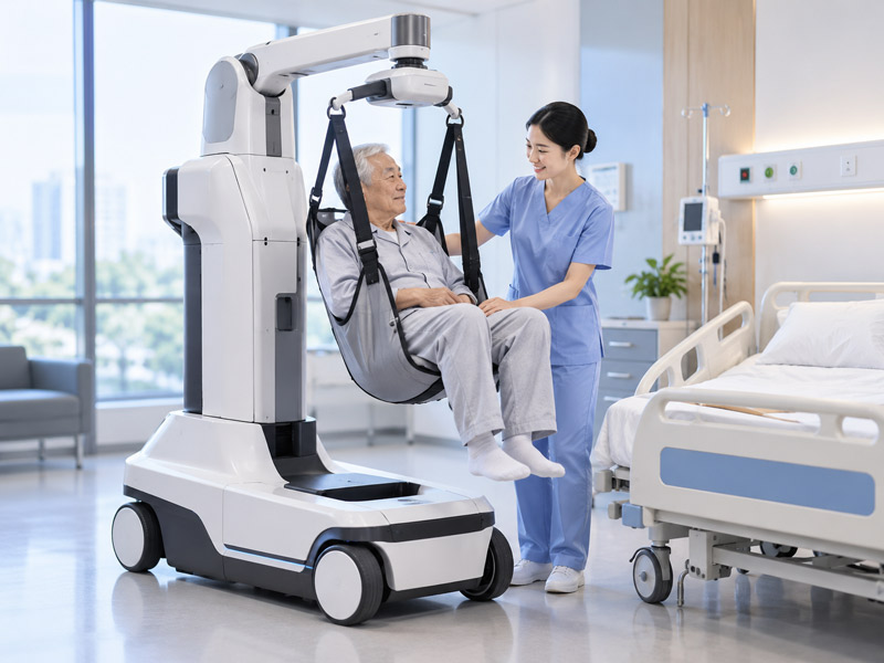
Patient transfer robots help move patients safely between beds, wheelchairs, and bathing facilities. Its core components include the lifting arm, chassis frame, push rod, and sensor bracket. The task of numerical control machining is to manufacture high-precision and highly reliable parts for these components

1.1 How CNC Machining Supports Patient Transfer Robot Systems
CNC machining and manufacturing of the chassis load-bearing frame, joint housing, lead screw, and bearing housing ensure smooth lifting and lateral movement of the equipment. Manufacture sensor mounting seats to ensure accurate force feedback and position data and prevent misoperation. The self-weight of the device is reduced through thin-walled design and weight-reducing holes, enhancing portability.
1.2 Why does patient transfer robot technology require more than just ordinary numerical control machining
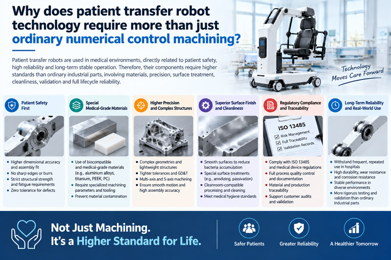
The patient transfer robot comes into direct contact with disabled patients, and the failure of its parts may cause personal injury. Therefore, higher safety redundancy and fatigue life are required; A smooth and burr-free surface (Ra < 0.8 μm); full-process traceability under the ISO 13485 quality system ensures that each part can be traced back to the raw materials and process parameters. Ordinary machining cannot meet these medical-grade requirements.
2. Which Patient Transfer Robot Parts Are Machined with CNC
CNC machining is widely used in robot joints, motion systems, structural components, sensors, and end effectors. Since each component has different functional requirements, the machining strategy should fully consider the component’s load-bearing method, the positioning method of adjacent parts, and the effect on motion.
2.1 Join Housings and Motor Mounts
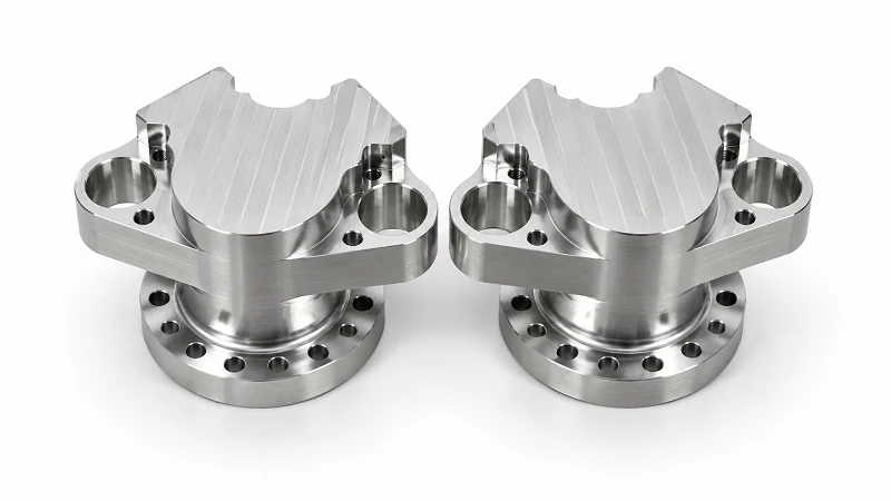
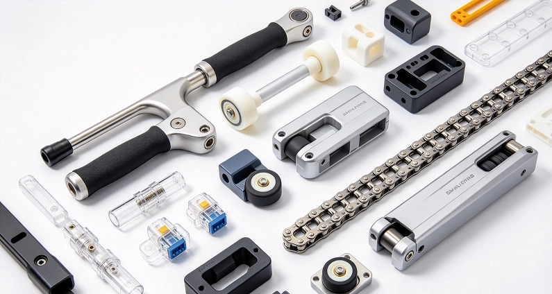
Typical moving parts include shafts, couplings, pulleys, gearbox housings, ball screw brackets, and planetary roller screw interfaces. CNC turning, milling, and turning-and-milling compound processing can form installation features, journals, holes, and reference surfaces. However, gears, ball screws, and planetary roller screws may also require special grinding, rolling, heat treatment, or finishing processes in addition to traditional CNC machining.
2.2 Structure and Lightweight Components
The robot arm, limb connector, trunk frame, end effector body, lightweight bracket, and thin-walled housing must strike a balance between strength, rigidity, and light weighting. Excessive material will increase inertia, while excessive weight reduction will make the parts prone to deformation during processing and clamping. Therefore, the tool path, workpiece clamping, and processing sequence should ensure rigidity while achieving the required wall thickness.
2.3 Sensors, Vision, and End Effector Components
| Robot System | CNC-Machined Parts | Key Requirements | Common Materials |
| Joints | Housings, motor mounts | Axis alignment, bearing fits | 6061, 7075, steel |
| Motion System | Shafts, couplings | Shaft diameter runout, shaft alignment | Steel, stainless steel |
| Structure | Arms, frames | Weight, stiffness | Aluminum, titanium |
| Sensors | Mounting brackets, bases | Flatness, position | Aluminum, stainless steel |
| End Effectors | Grippers, interfaces | Repeatability, alignment | Aluminum, steel |
Torque sensor mounts, camera mounts, calibration plates, gripper bodies, and tool change interfaces all rely on precise mounting references and hole positions. Flatness and perpendicularity help sensors and cameras maintain alignment. Controlled interface geometry supports repeatable positioning during gripper changes, calibration, assembly, and operation.
3. What Materials Are Used for Patient Transfer Robot CNC Parts
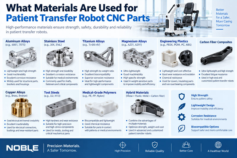
Material selection for robot CNC parts should consider load, weight, stiffness, temperature, wear, corrosion, electrical requirements, and working environment. The best material is not always the strongest. It must also meet requirements for practical machining, stable tolerances, surface treatment, and assembly.
3.1 Aluminum Alloys 6061 and 7075
The material selection for robot numerical control parts should take into account factors such as load, weight, stiffness, temperature, wear, corrosion, electrical requirements, and working environment. The best material is not always the strongest. It must also be capable of meeting the requirements of actual processing, stable tolerances, surface treatment, and assembly.
3.2 Aluminum alloys 6061 and 7075
Aluminum alloy 6061 is widely used in robot frames, shells, brackets, motor brackets, and general structural components due to its excellent processing performance, corrosion resistance, and a wide range of surface treatment options. Aluminum alloy 7075 has higher strength and is suitable for heavy-duty mechanical arms, joint structures, and compact components with high weight requirements. However, its elastic modulus is not significantly higher than that of 6061, so the geometry of the part still has a significant impact on the stiffness. Both alloys need to strictly control the processing sequence and tooling fixtures when they are thin-walled, deep-cavity, or where residual stress may cause deformation.
3.2 Stainless steel and high-strength steel
Stainless steel is often used to manufacture shafts, connectors, corrosion-resistant structures, precision interfaces, and components exposed to harsh environments. Alloy steel and high-strength steel are more suitable for manufacturing force-bearing shafts, transmission components, bearing surfaces and wear-resistant mechanisms. Compared with aluminium, these materials generate more cutting heat and tool wear. Some steel components still need to undergo heat treatment, grinding, surface hardening, or hardness testing to meet the final mechanical properties and dimensional requirements.
Titanium and Engineering Plastics
Titanium combines high strength, low density, and corrosion resistance, making it suitable for lightweight structures and harsh robotic environments. However, the concentrated heat generated during cutting increases the difficulty of processing. Engineering plastics, such as PEEK, POM, and UHMW, can be used as insulators, guide rails, sliding elements, wear-resistant strips, and low-friction components. When choosing these materials, factors such as temperature, load, humidity, dimensional stability, and coefficient of friction should be taken into account, rather than just processability.
| Material | Main Advantages | Machining Considerations | Typical Robot Parts |
| 6061 Aluminum | Machinability and corrosion resistance | Thin-wall deformation | Housings, brackets |
| 7075 Aluminum | Higher strength | Residual stress | Arms, joint structures |
| Stainless Steel | Strength and corrosion resistance | Heat damage and tool wear | Shafts, interfaces |
| Alloy Steel | Load capacity and wear resistance | Heat treatment deformation | Transmission parts |
| Titanium | Strength-to-weight ratio | Heat concentration | Lightweight structures |
| Engineering Plastics | Insulation and low friction | Burrs and deformation | Guides, insulators |
4. What CNC Machining Processes Are Commonly Used for Patient Transfer Robot Parts
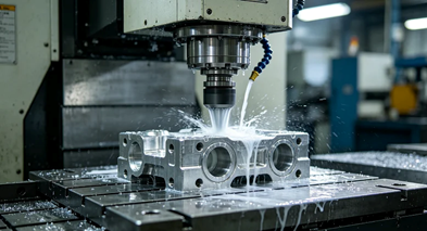
There are a wide variety of robot components, ranging from simple mounting plates to multi-axis joint housings and precision shafts. The appropriate numerical control machining process depends on the geometric shape, feature direction, tolerance relationship, production quantity, and the number of clamping times required to complete the part reliably.
4.1 CNC milling and 5-axis machining
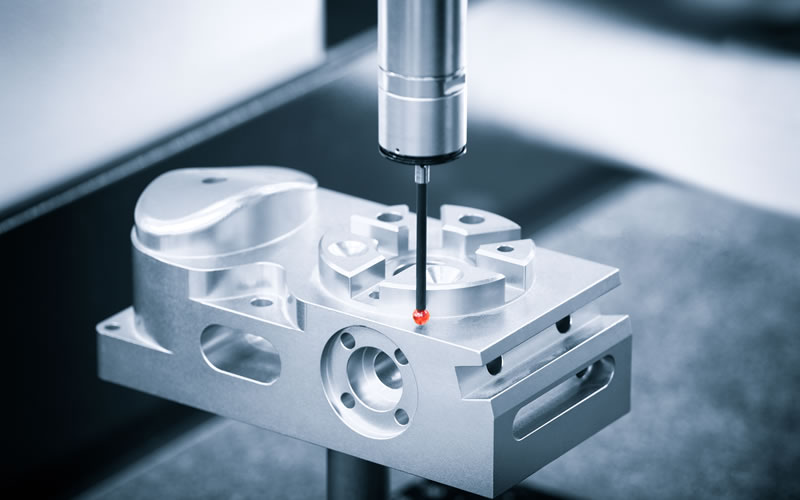
Three-axis milling is suitable for planes, holes, grooves, cavities, and structural components whose main features can be machined from conventional directions. For features located in multiple directions, 3+ 2-axis machining and 5-axis machining can provide varying degrees of tool access and motion control. In 3+ 2-axis machining, the workpiece is positioned at a fixed Angle before cutting, thus enabling the use of shorter and more rigid tools to process inclined features.
Five-axis linkage machining is more suitable for complex curved surfaces, inclined interfaces, deep features, and parts that require reduced clamping times. However, not all robot parts require five-axis machining. When the geometric shape and tolerance relationship do not require five-axis linkage, stable three-axis or 3+ 2-axis machining may be more economical.
4.2 CNC turning and turning and milling compound machining
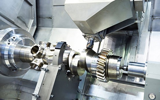
CNC turning is often used for the processing of robot shafts, pins, sleeves, couplings, bearing interfaces, and threaded connectors. It can effectively control the diameter, shoulder, groove, thread, and concentric rotation features. Turning and milling compound machining can add off-axis holes, planes, grooves or milling interfaces without transferring the parts to another machine tool. Reducing the number of re-clamping can improve the positional relationship between turning and milling features, especially for actuator shafts, couplings, and compact transmission components
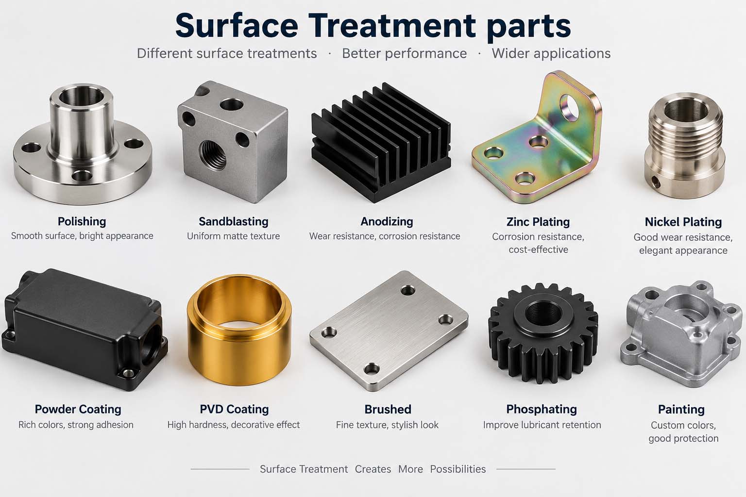
5. Secondary Operations and Surface Treatment for Patient Transfer Robots
Robot parts may still need to undergo treatments such as grinding, electrical discharge machining, heat treatment, anodizing, passivation, electroplating, sandblasting, or laser marking. Grinding can precisely process the key surfaces of bearings or shafts, while electrical discharge machining can process narrow grooves and features that are difficult to handle with traditional processing. Heat treatment can change mechanical properties, but it may also cause deformation. Coating and surface treatment can alter the hole diameter, shaft diameter, thread, electrical contact area, and fit. Before processing, these influences should be taken into account through dimensional compensation, masking instructions, tolerance planning, and final condition inspection.
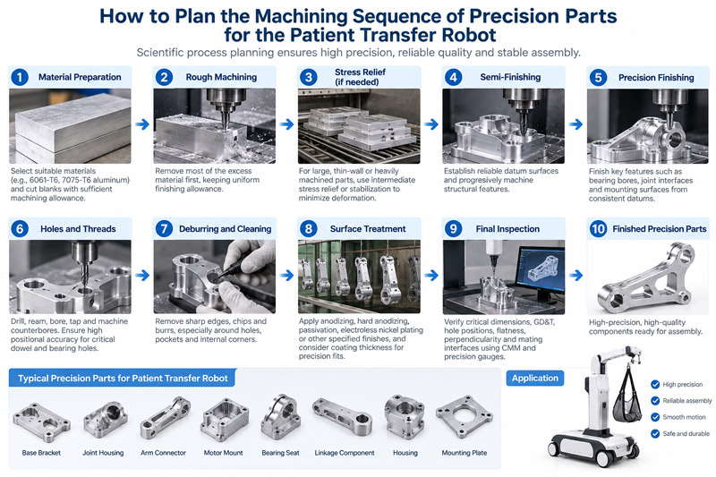
6. How should the machining sequence of precision parts for the patient transfer robot be planned
The processing sequence of precision parts for patient transfer robots needs to be systematically planned based on the functional requirements, structural complexity, and material properties of the parts to ensure the final dimensional accuracy and assembly consistency. The overall process can be divided into four stages: “rough machining → semi-finishing → finishing → post-treatment”.
Step 1: Rough machining and stress relief. The blank of the part (usually 7075 aluminum alloy or 304 stainless steel bar/plate) is first subjected to rough machining as a whole to quickly remove most of the allowance, leaving an allowance of 0.5- 1.0 mm for fine machining. For thin-walled frames and lifting arm shells, natural aging (24-48 hours) or artificial aging should be arranged after rough machining to release internal cutting stress and prevent subsequent deformation.
Step 2: Semi-finishing and reference correction. Taking the key surfaces after rough machining (such as the installation bottom surface or the main shaft hole) as the positioning reference, semi-finishing is carried out to further correct the hole position and contour, reserving a finishing allowance of 0.1- 0.2 mm. At the same time, non-critical features such as the threaded bottom hole and oil groove are completed.
Step 3: Fine processing and key feature forming. All key features are finely machined in one clamping, including bearing holes (tolerance ±0.01mm), sensor mounting surfaces (flatness < 0.02 mm), locating pin holes, and threads. Adopt five-axis linkage or high-precision three-axis machine tools to reduce the cumulative error caused by multiple flips.
Step 4: Post-processing and final inspection. After the fine processing is completed, deburring, cleaning, and surface treatment (such as hard anodizing) are carried out. All key dimensions should be remeasured using a CMM coordinate measuring machine. Only after confirming that there are no deviations can they be transferred to assembly. The entire process must retain complete process records to meet the traceability requirements of ISO 13485.
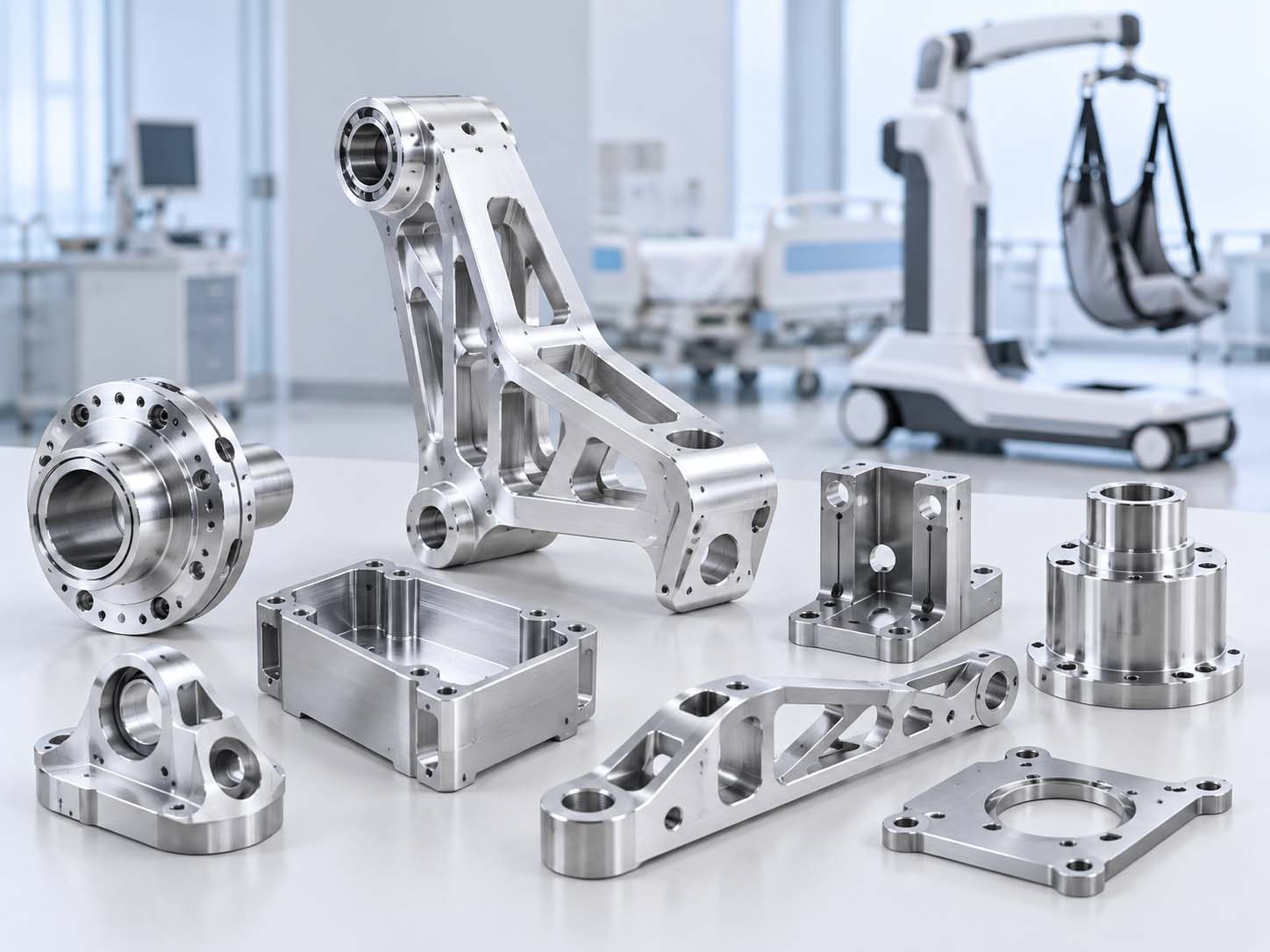
7. What Are the Difficulties in Machining Patient Transfer Robot Precision Parts
- Thin-wall deformation: Frames and lifting arms have a wall thickness of only 2- 3 mm. They are prone to warping and deformation during cutting.
- Multi-hole concentricity: Bearing mounting hole concentricity must be controlled within 0.01mm. Multiple setups make this difficult to guarantee.
- Surface safety requirements: Parts that contact the human body need surface roughness Ra < 0.8 μm. No burrs or sharp edges are allowed.
- Difficult materials: 7075 aluminum and 304 stainless steel are hard to control in thin-wall conditions during cutting.
- Complete traceability: Process parameters for every part must be fully recorded to meet ISO 13485 traceability requirements.
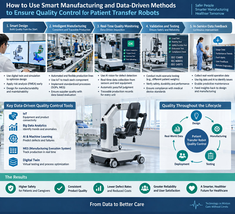
8. How to Use Smart Manufacturing and Data-Driven Methods to Ensure Quality Control for Patient Transfer Robots
Through online monitoring and real-time feedback, sensors are used to monitor cutting force and vibration during processing. Combined with big data analysis, tool wear and dimensional deviations are predicted, and early intervention is carried out.SPC statistical process control is adopted to collect and analyze key dimensions in real time. An automatic alarm is triggered when a trend offset is detected. Establish a full life cycle quality traceability system, integrating raw material batches, processing parameters, and test results on a unified platform to achieve “one-code traceability” for each part and ensure compliance with ISO 13485 requirements. Meanwhile, surface defects (scratches, burrs) are automatically identified through AI visual inspection, replacing manual visual inspection and enhancing inspection efficiency and consistency.
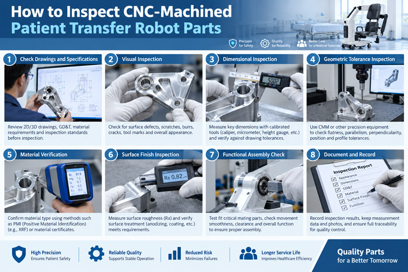
9. How to Inspect CNC-Machined Patient Transfer Robot Parts
The inspection process is divided into three stages: incoming material inspection to verify the material report and the size of the blank. Process inspection is carried out through initial inspection, patrol inspection, and final inspection. Key dimensions are randomly inspected online using a three-coordinate measuring machine (CMM). The finished product inspection conducts 100% testing on all key features (aperture, flatness, surface roughness).
At the same time, functional tests are conducted: simulate assembly to verify the coaxiality of the bearing holes, and use force sensors to verify the accuracy of the installation surface. Each part is accompanied by a test report to ensure compliance with the drawing requirements and ISO 13485 traceability standards.
10. How to Choose a CNC Machining Supplier for Medical Robot Parts
Ask the supplier if they understand assembly tolerance chains, bearing and motor interfaces, lightweight structures, multi-axis motion parts, and design changes between prototype and production. Relevant engineering experience is more important than simply claiming to have made “robot parts.”
10.1 Proven Accuracy and Process Capability
Review similar parts, inspection reports, materials, work holding methods, and critical dimension control. Confirm that the supplier can maintain consistency across entire batches, not just individual samples. Machine specifications describe the potential capability of equipment. They do not prove process stability.
10.2 Quality System and Traceability
Check applicable ISO certifications, material control, revision management, First Article Inspection (FAI) and inspection records, non-conforming material handling, and batch traceability. These controls should link every delivered part to the correct drawing revision, material batch, production batch, and inspection results.
10.3 Engineering Response and Delivery Capability
Evaluate the quality of DFM feedback, clarity of quotation assumptions, prototype and production lead times, and response speed to engineering changes. For robot projects, suppliers should also show their actual ability to support high-mix, low-volume production and repeat orders.
| Evaluation Area | What to Check | Warning Signs |
| Accuracy | Similar parts and reports | Machine specifications only |
| Robot Experience | Assembly and motion interfaces | General capability claims |
| Quality | FAI, traceability, revision control | No documented processes |
| Scalability | Plan from prototype to production | Only successful once |
| Communication | Clear DFM and assumptions | Quotations without technical review |
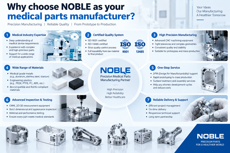
11. Why choose NOBLE as your medical parts manufacturer?
NOBLE is a certified metalworking company with over 12 years of experience in manufacturing high-quality metal components.
From our locations in Shenzhen, China, we provide sheet metal machining and precision mechanical components for the automotive, robotics, and medical industries. Since 2012, we have acted as a trusted partner for manufacturers of components for industrial vehicles and Robot parts, offering a full production path from initial processing through to finished parts.
What makes us different is our focus on technological innovation and constant improvement. By pairing advanced automation with expert craftsmanship, we ensure every component satisfies rigorous quality standards. Our facilities are certified to ISO 9001 and ISO 13485, reinforcing our commitment to quality management, environmental responsibility, and workplace safety.
This gives companies like yours a reliable partner for consistent, high-precision components, complete traceability, and full compliance with international standards. From complex sheet metal fabrications to mechanical components for demanding uses, our team is equipped to meet your production goals.
FAQs of the Patient Transfer Robot:
1. What Is The Difference Between a CNC Mill and a Robotic Arm?
From my experience, the key difference lies in structure and function. A CNC mill is a rigid, high-precision machine—ideal for subtractive tasks like milling and drilling, often achieving ±0.005 mm tolerance. In contrast, a robotic arm offers greater flexibility with 6+ degrees of freedom, making it suitable for multi-task operations like pick-and-place, welding, or light machining. However, its positional accuracy is typically lower—around ±0.05 mm—unless enhanced with vision systems.
2. What Is A CNC in Robotics?
CNC controls machine tools digitally. In robotics, it processes precise mechanical parts for robot structures.
3. Is A Robotic Arm Suited To Use For CNC Milling Of Components?
Yes, a robotic arm can be used for CNC milling, especially for large or complex parts. I’ve worked on setups where 6-axis robotic arms handled freeform surfaces with ±0.1 mm accuracy. While they don’t match the stiffness or ±0.002 mm precision of traditional CNC mills, they excel in flexibility, reach, and multi-angle tool paths—ideal for trimming composites, large molds, or when space constraints exist.
4. How to make A CNC Robotic Arm?
Design the structure, select parts, machine by CNC, assemble, and debug the robotic arm.
5. How Is Robotics Used In The Automotive Industry?
Robots handle welding, assembly, and painting, improving car-making speed and product consistency.