Introduction – The Essence of Strength and Stiffness Design
Structural strength stops the part from breaking. Stiffness design stops it from bending too much. While these two concepts sound similar, they are actually distinct.
The former handles irreversible failure—cracks, fractures, collapse. The latter handles elastic deformation—deflection, twist, vibration. Different physics. Different calculations. Different fixes.
Throwing more material at the problem is the easy move. Although effective, this approach is costly and results in bulky components. A wise design strategically guides load paths—this is known as load path optimization.
Sharp turns create stress concentrations. This is where stress concentration relief comes into play. Rounding corners and ensuring smooth transitions at changes in cross-section are key. These subtle details can make a significant difference.
Strength and stiffness are not a trade-off. They are a balance. The right material in the right shape with the right load path. That is the essence.
Load Path Architecture – The Skeleton of Stiffness Design
The Shortest Load Path Principle
A load is applied at a certain point and unloaded at the support. The distance between the two should be as short as possible. If the distance is too long, bending will occur. Bending stress will increase, and deflection will also increase. This is not a subjective assumption, but a law of statistics.
Geometric proximity is non-negotiable. Place the support near the load, and place the load near the support. If the two are far apart, the bending moment will increase linearly with distance, stresses will rise accordingly, and deflection will increase proportionally to the cube of the distance. This will lead to extremely severe consequences. Load path optimization starts with this rule.
The Cost of Cantilevers
A cantilever is a beam fixed at one end. The load hangs off the other. Stiffness drops with the cube of the length. Double the length. Stiffness drops to one-eighth. That is not incremental. That is catastrophic.
The physics is intuitive. The free end moves a lot. The fixed end does not. The material near the support carries the whole load. The material near the free end contributes little. Back-to-back bracing changes the game. Two cantilevers facing each other share the load. The deflection drops. The effective stiffness rises. The cantilever effect gets eliminated.
Redundancy vs. Single- Path Dependency
A single load path is relatively vulnerable. Once a failure occurs, the path is severed, and the structure collapses. Multiple paths, however, provide redundancy. If one path fails, the load is transferred to another path.
This improves damage tolerance. It gives the structure time to signal a problem. It also improves structural toughness—the ability to absorb energy before failure. The cost is complexity. Secondary paths must be placed without interfering with the primary path.
Eliminating “Freeloading” Components
Some components do not bear any load; they are simply there. They add mass and increase costs, but serve no other purpose.
If a component does not actively carry load, it has two options. Remove it entirely. Or connect it through a flexible interface—a rubber mount, a slip joint, a gap. A rigid connection to a non-load-bearing part creates unintended stiffness. It interferes with the designed load path. It adds stress and complexity. That is a bad stiffness design.
Every structural component must justify its existence. If it does not carry load, it must not affect stiffness. That is the minimum standard. Anything else is parasitic and should be cut.
For slender members, the slenderness ratio buckling becomes a concern. In a slender column under compression, the buckling stress is much lower than its compressive strength. The critical load is determined by the ratio of the length to the radius of gyration. This ratio should be kept low, or lateral bracing should be added.
Dynamic Duty Cycles – Shock, Vibration, and Structural Strength
Static loads are predictable, but dynamic loads are not. Impact, vibration, and cyclic stress—these factors change the game.
Rethinking Friction as a Force-Transmission Mechanism
Friction clamps the two components together. Bolts provide the force. This joint relies on friction to transfer loads. Under static conditions, this method is feasible. However, under vibrating conditions, the coefficient of friction fluctuates—sometimes dropping, sometimes surging—and becomes unpredictable.
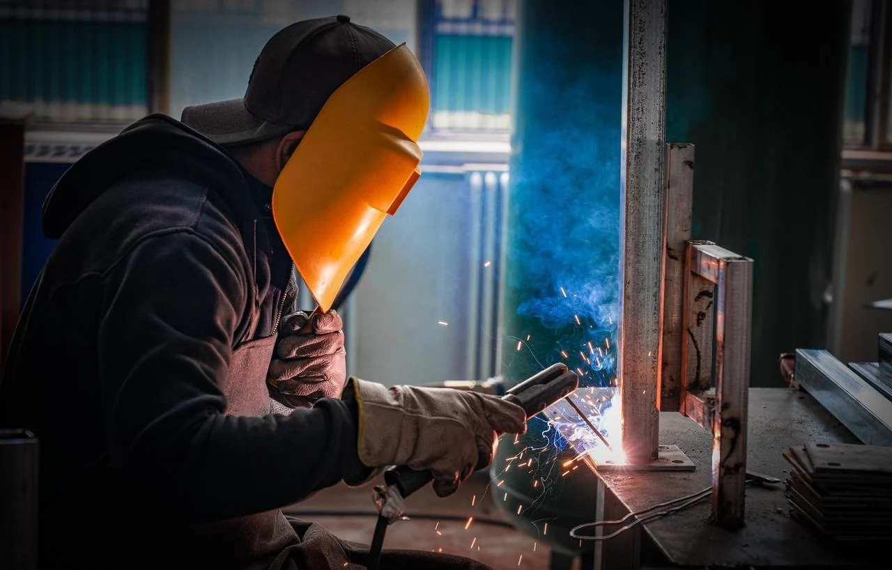
The reliable alternative is form-locking vs. a friction joint. Examples include keys, splines, shoulders, or mechanical interlocks. The load is transmitted through the geometric structure rather than friction. Welded joints offer even better performance. The joint becomes a continuous metal structure that does not slip, does not wear, and does not exhibit instability.
Balancing Inertial Forces
Unbalanced forces are the root cause of periodic vibration in rotating machinery. High-speed assemblies demand dynamic balancing—this is not optional.
High-speed assemblies demand dynamic balancing. Not optional. Not adjustable in the field. The inertia forces must cancel each other out. Residual imbalance creates a cyclic load that degrades structural strength over time.
Load Redistribution Under Large Deformation
Minor deflections preserve the linearity of the geometry. The support points remain unchanged. Loads are transferred to their intended locations.
However, significant deflections change everything. Support points bend. Gaps close. Contact surfaces displace. The original constraints no longer hold. Loads are redistributed.
The linear assumption no longer applies. Nonlinear FEA contact stiffness becomes the right tool. The analysis must account for changes in contact area, applied forces, and load paths. As the geometry changes, the model must be updated accordingly.
Toughness-Oriented Stiffness Design
Stiffness is not always good. Under impact, a very stiff structure does not absorb energy. It transfers all the force to the next component. The force is then amplified, ultimately leading to component failure.
This is closely related to fatigue issues. Impacts cause microscopic damage. Dents appear on the surface. These dents act as stress concentration points. Fatigue due to surface integrity failure begins at these damaged areas. Smooth surfaces can delay fatigue, while rough surfaces accelerate it. Protect the surface, protect the joint, and protect the structure.
Here is the link to fatigue. Impacts create microscopic damage. The surface gets dented. A dent is a stress raiser. Surface integrity fatigue initiation starts at these damaged spots. Smooth surfaces delay it. Rough surfaces accelerate it. Protect the surface. Protect the joint. Protect the structure.

Fatigue and Stress Concentrations – Local Threats to Structural Strength
The macro-design handles the big forces. The micro-details handle the cracks. Ignore the micro-details, and structural strength drops fast.
Surface Integrity
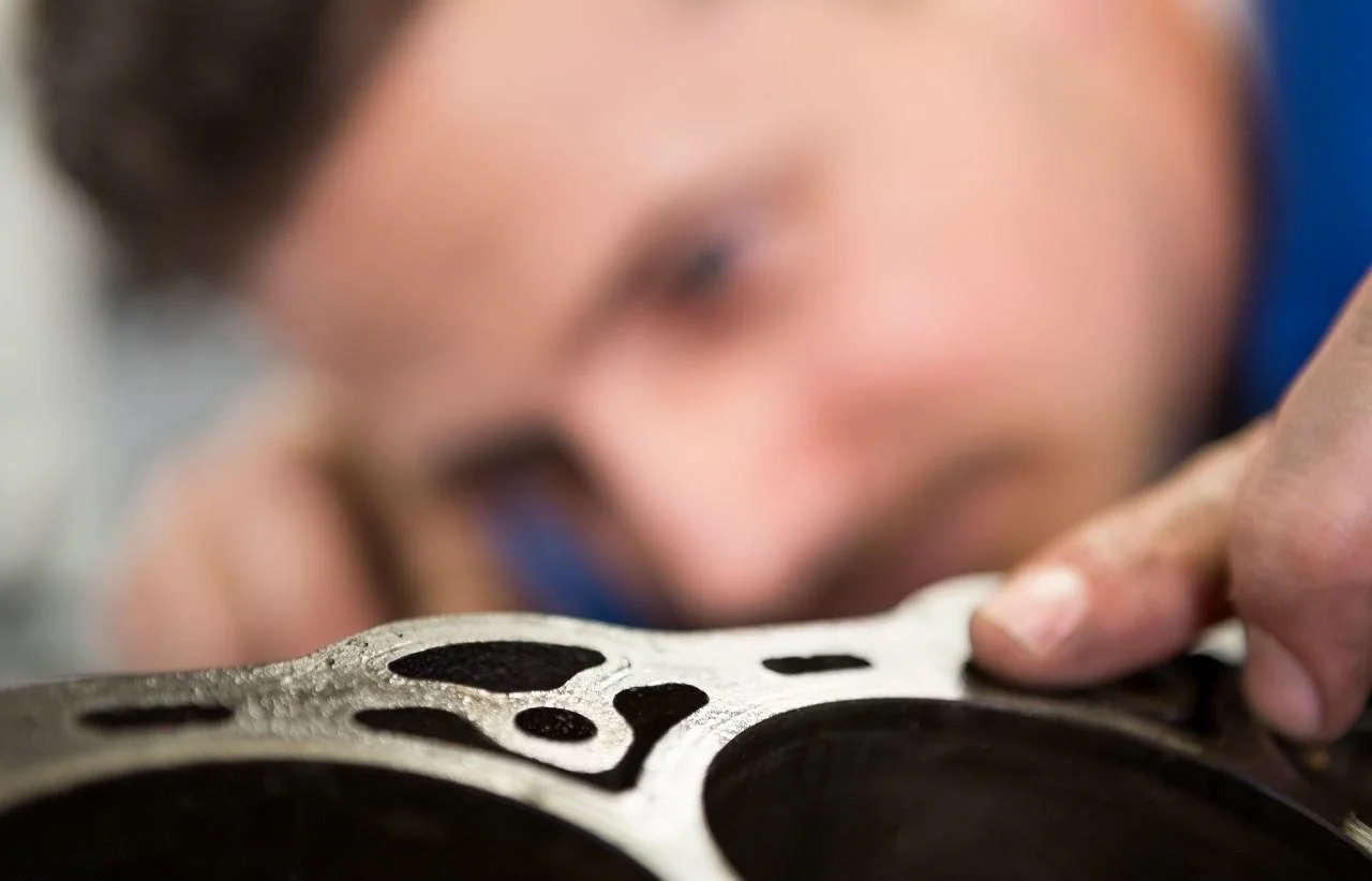
Scratches, tool marks, and grinding scorch marks—these are not merely surface imperfections, but the starting points of cracks.
Surface integrity fatigue initiation starts at the bottom of a scratch. Stress concentrates at this point, and cracks begin to propagate from there. Critical surfaces must be polished. Roll finishing is equally effective; it compacts the surface and eliminates microscopic notches, thereby extending the service life of the part.
Managing Residual Stresses
Tensile residual stress is a crack driver. It pulls the crack open. Compressive residual stress does the opposite. It squeezes the crack closed.
Shot peening creates compressive stress at the surface. Nitriding does the same. The surface layer gets compressed. The crack initiation delays. The fatigue life extends.
The autofrettage effect is similar. Over-pressurize a thick cylinder. The inner wall yields in tension. When the pressure releases, the inner wall stays in compression. The cylinder can now handle higher service pressure without fatigue failure. The principle applies to other components too. Pre-stress the tension side. The service load then works against the pre-stress. Net stress stays lower.
Superposition of Stress Concentrations
Two stress raisers near each other are worse than one. Their stress fields overlap. The peak stress at the combined location exceeds the sum of the individual peaks. That is superposition.
Stress raiser mitigation requires separation. Keep the notches far apart. If space is tight, introduce a relief groove between them. The groove interrupts the stress field. It decouples the two raisers. The peak drops.
The “Same-Direction” Deformation Trap
Pre-deformation has been taken into account in the design. During assembly, the part will bend and be clamped into place. When a service load acts in the same direction, the deflection accumulates, doubling the total deflection and, consequently, the stress.
Pre-deformation is designed to counteract service deformation. The part bends in one direction during assembly, while service loads bend it in the opposite direction. The net deformation remains small, and the stress remains low. Stiffness design must account for both directions simultaneously: preload and service load. They do not exist independently but interact with one another. This interaction must be carefully designed.

Material Behaviors – Cast Iron, Wire Rope, and Special-Case Pitfalls
Materials are not generic. Each has quirks. Design for the quirk, not the average property.
Cast Iron – Compression vs. Tension
Cast iron has high strength under compression but low strength under tension. The flake graphite within the material acts as a stress concentration point. Under tensile stress, cracks initiate and propagate from the graphite flakes; under compressive stress, the graphite flakes are squeezed together, allowing the material to remain intact.
Slender Members and Buckling
A slender rod under bending is unstable. It deflects sideways. The bending moment increases. The deflection grows. The rod buckles suddenly. No warning. Just collapse.
The solution is simple. Shift the rod into tension. A tension member cannot buckle. If tension is not possible, add intermediate supports. Reduce the unsupported length. Slenderness ratio buckling depends on the length divided by the radius of gyration. Keep that number low, and the buckling load stays high.
Wire Rope – The Curse of Bending Fatigue
Wire rope bends over sheaves. It bends around drums. Each bend creates stress at the rope surface. The outer wires stretch. The inner wires compress. The rope bends again. The stress reverses. Fatigue starts.
Surface damage accelerates surface integrity fatigue initiation. A broken outer wire is a stress raiser. It cuts adjacent wires. The rope fails strand by strand.
Sheave diameter matters. Drum diameter matters. The D/d ratio—sheave diameter divided by rope diameter—must meet code minimums. Smaller diameters kill rope life faster. Repeated bending at the same spot doubles the damage. Change the fleet angle. Shift the landing point. Spread the wear.
Safety Margins at Rope End Terminations
The rope ends at a drum. A clamp plate holds it. The stress at the clamp is high. The bending is sharp. The fatigue is concentrated.
Leave extra rope length at the drum. The extra wraps reduce the stress at the clamp. The load spreads over more turns. The clamp plate sees lower stress. This is not optional. It is a non-negotiable safety rule in crane design. The stiffness design of the drum connection must account for the termination zone. The rope must not bend sharply at the clamp. The radius must be generous. The safety margin must be real. Not just calculated. Tested.
Manufacturing Realities – Misalignment, Foundations, and Hidden Loads
The Amplifying Effect of Misalignment
A shaft is supposed to be straight. The bearings are supposed to be coaxial. In practice, they are not. The misalignment creates bending moments. The bearings overheat. The seals leak. The shaft flexes.
The principle behind self-aligning bearings’ eccentricity compensation relies on bearings that can tilt to accommodate shaft displacement. By utilizing spherical rollers and curved raceways, the bearings can automatically adjust, thereby reducing torque. The same applies to flexible couplings. They can absorb angular misalignment and isolate the shaft from the housing.
Foundation Reaction Forces
The equipment is mounted on a foundation, which in turn is built on the soil. Uneven settlement of the soil can cause the equipment to tilt. This alters the alignment, which in turn generates secondary stresses.
Reducing transmitted force to the foundation is not just about vibration isolation. It prevents foundation settlement from secondary stress. Smaller reaction forces mean smaller foundation tilts. The machine stays level. The stresses stay low.
A Counterintuitive Upside: Beneficial Service Loads
Pressure vessels work under internal pressure. The pressure expands the vessel. The inner wall yields in tension. When the pressure releases, the inner wall stays in compression. This is the autofrettage effect.
The compressed inner wall now resists the next pressure cycle. The net stress is lower. The fatigue life is longer. This is an advanced tactic. It uses the service load to improve the part’s response. The vessel becomes stronger in use than it was before pressurization. That is an elegant design. It turns a challenge into a benefit for structural strength.

Talking to NOBE
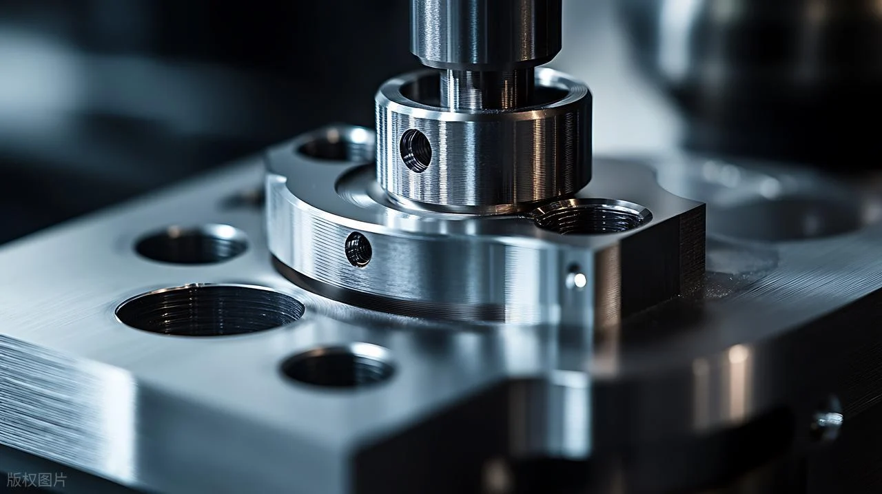
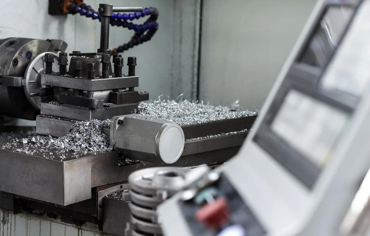
NOBLE is a precision manufacturing house. CNC machining and sheet metal fabrication are the core disciplines. The shop does not just read about load paths—it cuts, forms, welds, and assembles them daily. Stress concentrations meet the toolpaths on the machine. Cantilever stiffness meets weld fixturing at the table. Surface integrity meets coolant strategy at the cutting edge. That is the daily reality.
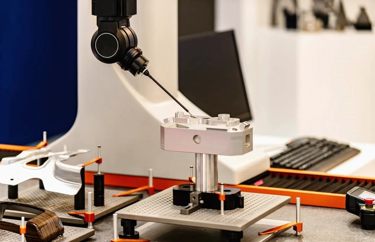
Certified Quality Infrastructure
ISO 9001:2015 covers quality management. ISO 13485:2016 covers medical device manufacturing. These are not wall decorations. They are operating in a disciplined manner. For industries where fatigue life, dimensional stability, and traceability are non-negotiable, the certifications provide an audit-ready framework.
One Partner, Full Lifecycle
The capability goes beyond machining and bending. It covers the full lifecycle.
Design for Manufacturability reviews the geometry against the principles in this article. Shortening load paths. Mitigating stress raisers. Selecting compatible materials. Anticipating assembly misalignments before the drawing releases. That is load path optimization and stress raiser mitigation applied at the design stage.
Prototyping and process development validate that stiffness design and structural strength targets survive the transition from CAD to chip. Rapid iteration. Process validation. No surprises in production.
Production machining and fabrication include multi-axis CNC milling and turning, precision sheet metal cutting, bending, and welding. Controlled residual stress management. Surface finish protocols. Surface integrity fatigue initiation gets addressed before the part leaves the machine.
Assembly and integration complete the chain. Subassemblies. Hardware integration. Functional testing. The vendor chain shrinks. Quality risk drops. The parts ship as solutions, not as components.
FAQ
Is stiffness more important than strength, or the other way around?
Stiffness comes first. Without it, deformation redistributes stress, and structural strength specs become meaningless.
Does adding more material always make a part stronger?
No—it is the laziest fix. Smarter load paths give more strength with less weight, which is the essence of good stiffness design.
What’s the biggest killer of fatigue life?
Surface condition. Scratches and roughness are crack starters—polish or burnish high-stress areas to prevent surface integrity fatigue initiation.
Why does cast iron fail so easily in tension?
It is strong in compression but weak in tension. Design cast parts to be pushed, not pulled.
What’s the difference between a parts producer and a full-service manufacturer?
A parts producer just cuts metal. A full-service partner handles design, prototyping, machining, assembly, and quality—under one roof.
Does NOBLE do assembly or just machining?
Both. The service covers raw materials to ready-to-install assemblies, not just loose components.
Can you help improve my existing design for manufacturability?
Absolutely. We review your prints, suggest DFM improvements, and machine it right the first time.