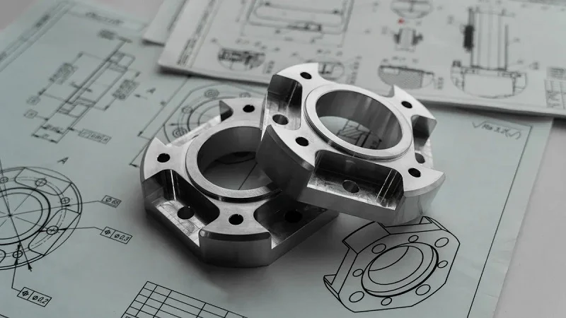
Precision motion components power modern factories. Robotic arms and EV assembly lines rely on them every second. The market shows this need. Experts expect it to grow 10.4% each year from 2026 to 2033, hitting $12.2 billion in 2024. The materials and manufacturing methods decide how accurate, repeatable, and long-lasting the system is.
Reshoring also changes how suppliers are chosen. In 2024, companies announced 244,000 reshoring jobs. Industrial equipment projects, like those from German precision toolmakers, rose sharply from January 2022 to April 2025. Electric power capacity is now the top factor when picking a site.
| Evidence Type | Detail | Relevance |
| Job announcements | 244,000 jobs in 2024 | Reshoring intensity |
| Industrial projects | ~200 FDI projects | Precision manufacturing activity |
| Site selection | Power capacity #1 | Supplier criteria |
How do you pick materials for common precision motion control uses? Which processes ensure the right tolerances? How do you balance cost with precision motion control? This guide answers these questions for engineers and purchasing teams who want reliable, repeatable operation and strong performance in precision motion control systems.
Material Selection for Precision Motion Components
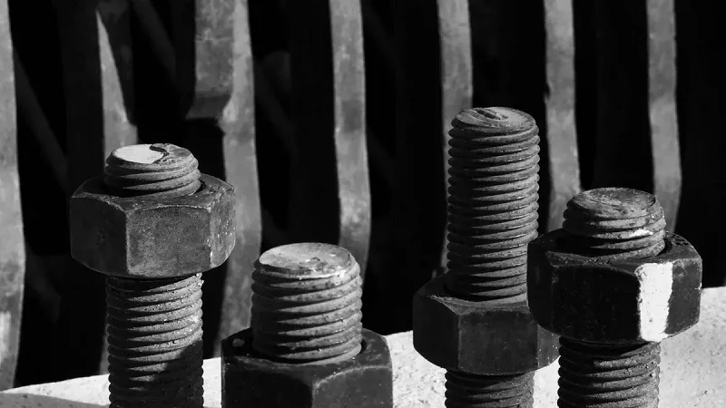
The material you pick changes how accurate and repeatable the final system will be. Also think about performance and cost. Each material has different pros and cons.
Metals for Strength and Stiffness
Metals are the main part of most precision motion control systems. They handle big loads and keep their shape under stress. How precise the assembly is depends on the material’s stability.
Steel Alloys for High Loads
Steel alloys give the highest absolute strength. Carbon steel reaches 570 MPa tensile with a 330 MPa yield. Stainless steel gets 515 MPa tensile at Rockwell B88 hardness. For very high wear, hardened steel goes to 65 HRC or 900 HV. Steel is the choice when loads are high and bending must be very small. But steel is heavy at 7.8 g/cm³. For fixed parts like guide rails or machine frames, that is fine. For moving parts, think about lighter options.
Aluminum and Titanium for Lightweighting
Aluminum 7075-T6 has a tensile strength of about 540 MPa and a density of only 2.7 g/cm³. Its specific strength is roughly 196 kN·m/kg. Steel gives about 150 kN·m/kg. So aluminum carries more load per pound, even though its absolute strength is lower. For high-speed motion, weight matters.
Titanium Ti-6Al-4V reaches about 900 MPa tensile strength with a yield of 828 MPa. Density is 4.5 g/cm³. Its specific strength of about 187 kN·m/kg beats steel. Titanium is a good choice for precision positioning stages. The trade-off is how easy it is to machine. Titanium wears tools faster. Aluminum machines easily but may not hold up under high cyclic loads. Steel offers the best fatigue life but adds weight. For precision motion control, moving mass affects acceleration.
Ceramics and Carbides for Extreme Conditions
Some jobs push beyond what metals can handle. High heat, abrasive wear, or chemical exposure call for ceramics and carbides.
Thermal Stability and Hardness
Ceramic composites reach hardness up to 1200 HV. That is harder than hardened steel at 900 HV. Chromium alloys hit 1100 HV. Ceramics stay stiff at high temperatures. For precision motion control in semiconductor manufacturing, that thermal stability matters. The manufacturing process needs special equipment.
Brittleness and Machining Challenges
The downside is brittleness. Ceramics do not bend; they break. A small impact causes cracks. Machining is hard. Normal cutting tools wear down fast. Diamond grinding or ultrasonic machining is often needed. That raises cost and cycle time. Use ceramics only when the environment demands it.
Polymers and Composites for Specialized Needs
Plastics offer low friction, self-lubrication, and chemical resistance. They work well for certain precision mechanical parts.
Low Friction and Self-Lubricating Plastics
PEEK has a tensile strength of 14,000 to 16,000 psi. Torlon 4203 reaches 18,000 psi tensile with 24,000 psi compressive. Its modulus is 600,000 psi. PAI offers good wear resistance at high speeds. Vespel keeps low friction in dry environments beyond 300°C. For mechanical motion parts like bushings, these materials reduce the need for external lubrication.
For precision linear motion parts, polyacetal shows a wear rate 30-40% lower than Nylon 66. Its PV limit is 0.28-0.37 MPa·m/s. The best counterface roughness is 0.1-0.3 μm Ra. In automation systems, these properties make maintenance intervals longer. The accuracy of these parts depends on material stability. Steady repeatability is possible with the right grade.
Dimensional Stability and Environmental Limits
Temperature and moisture change polymer size. UHMW has a CTE of 0.0001 inch/degree. That causes 0.012 inches of movement per degree in a 10-foot piece. PTFE ranges from 112-135 × 10⁻⁶/°C. Glass-fiber-reinforced plastics are lower at 21-36 × 10⁻⁶/°C.
Moisture matters too. Nylon 6 absorbs 1.5-2% moisture at 35-65% RH. Fully soaked, it absorbs 5-8%, causing a 2% length increase. Acetal and PEEK hold ±0.001-inch tolerances. Nylon and PVC manage ±0.002 inches. UHMW and HDPE are limited to ±0.005 inches. For these parts, the design process must account for environmental changes.
For high-accuracy uses, choose materials with low CTE and low moisture absorption. Glass-filled Ultem has a flexural modulus of 1,300,000 psi. That stiffness helps keep dimensional stability under load. The right material choice for precision motion control depends on the environment, load profile, and required precision. For manufacturing machines, the same ideas apply. In high-volume automation, cycle time matters. Repeatability is key for steady performance.
Manufacturing Processes for Precision Motion Components
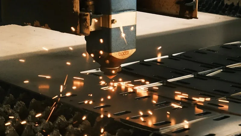
The material you choose sets the ceiling. The manufacturing process decides how close you get to that ceiling. Each method brings different strengths to the table. Some excel at tight tolerances. Others shine with complex shapes. Knowing which process fits your part saves time, money, and frustration.
High-Precision CNC Machining
CNC machining remains the workhorse for precision motion components. Modern mills and lathes hold consistent tolerances that would have seemed impossible a generation ago. High-end machines routinely hit ±0.001 inches. Some reach ±0.0002 inches depending on material, geometry, and machine condition. That level of precision makes CNC the default choice for many motion control parts.
| Technology | Achievable Tolerance | Surface Finish | Key Application |
| CNC Machining | ±0.001 mm (0.00004 inches) | Not specified | Aerospace, automotive, medical devices, electronics |
| EDM | ±0.002 mm (0.00008 inches) | Excellent | Mold making, aerospace components, precision tooling |
| Ultra-Precision Grinding | ±0.001 mm (0.00004 inches) | Ra 0.01 µm | Optical components, aerospace parts, bearings |
Achieving Tight Tolerances
Tighter tolerances cost more. Machining time grows. Tooling wears faster. Inspection demands more resources. Plastics add another wrinkle. They expand and warp with temperature changes. Slightly looser tolerances or specific material grades help maintain stability. For aerospace work, CNC machining routinely achieves ±0.025 mm. Turbine seals and avionics housings push to ±0.005 mm. That gap between routine and exceptional shows what careful process control can deliver.
Fixturing and Tooling Considerations
Fixturing makes or breaks precision work. A part that shifts during machining ruins accuracy. Five-axis machines reduce this risk. They cut from multiple angles in one setup, eliminating the misalignment that comes from repositioning. That single change improves process repeatability dramatically. Tool selection matters too. Sharp, rigid tools cut cleaner. Proper speeds and feeds prevent deflection. For high-volume production, documented processes and consistent tooling keep quality steady across thousands of parts.
Grinding and Lapping for Surface Finish
Sometimes dimensional tolerance is only half the story. Surface finish affects friction, wear, and sealing. Grinding and lapping deliver finishes that standard machining cannot touch.
| Technique | Key Capability | Achievable Surface Finish |
| Double Disk Grinding | Grinds two sides simultaneously using opposing abrasive wheels; provides consistent part-to-part parallelism and flatness; suitable for mass production | Up to 16 Ra µin (0.41 µm) on aluminum; up to Ra 8 µin (0.20 µm) on ferrous alloys |
Sub-Micron Flatness and Parallelism
Double disk grinding stands out for parallel parts. Two abrasive wheels grind both sides at once. Parts feed automatically through a 120° arc. Equal material removal from both sides produces flatness and parallelism that surface grinding struggles to match. Precision lapping goes further. This superfinishing technique uses a three-body abrasive action. The workpiece, a soft cast iron or composite plate, and an abrasive slurry work together. Loose abrasives roll and slide against the part, shearing off microscopic peaks. The result is a smooth, non-directional finish. Precision lapping achieves tolerances on a sub-micron scale. Batch after batch, thickness control stays remarkably tight.
The Role of Abrasives in Dimensional Accuracy
Abrasive selection drives lapping results. Aluminum oxide, silicon carbide, and diamond each behave differently. Particle size, concentration, and type depend on the workpiece material and desired finish. Lapping operates at low pressure and low temperature. That means no stress or thermal distortion. The process corrects geometric errors left by earlier grinding steps. For precision motion control systems, this surface quality translates directly into smoother operation and longer precision motion component life.
Advanced Methods: EDM and Additive Manufacturing
Some geometries defy conventional machining. Deep slots, tiny holes, and intricate internal features push traditional tools to their limits. Two advanced methods fill the gap.
| Technology | Precision (Tolerance) | Cost Profile | Complexity Handling |
| Wire EDM | ±0.005 mm | High operational cost; cost-effective for hard materials or intricate features | Excellent for intricate 2D profiles and complex shapes in conductive materials |
| 3D Printing (SLA/MJF) | ±0.05 to ±0.1 mm | Lowest cost for low volumes; cost less correlated with geometric complexity | Excels at highly complex geometries, internal structures, and organic shapes |
| 3D Printing (FDM) | ±0.2 mm | Lowest cost for initial concept models | Good for rapid iterations but limited by lower accuracy |
Wire EDM for Complex Geometries
Wire EDM cuts with electrical sparks instead of physical tools. That means no tool wear, no chipping, no breakage. The process holds tolerances within ±0.005 mm. Inside corner radii can go as small as 0.003 inches. The surface finish comes out incredibly smooth, often reducing post-processing needs. EDM only works on electrically conductive materials. Metals and conductive ceramics qualify. Plastics do not. For hard materials or intricate features, EDM often costs less than conventional machining despite its high operational expense.
When to Use 3D Printing for Prototypes and End-Use Parts
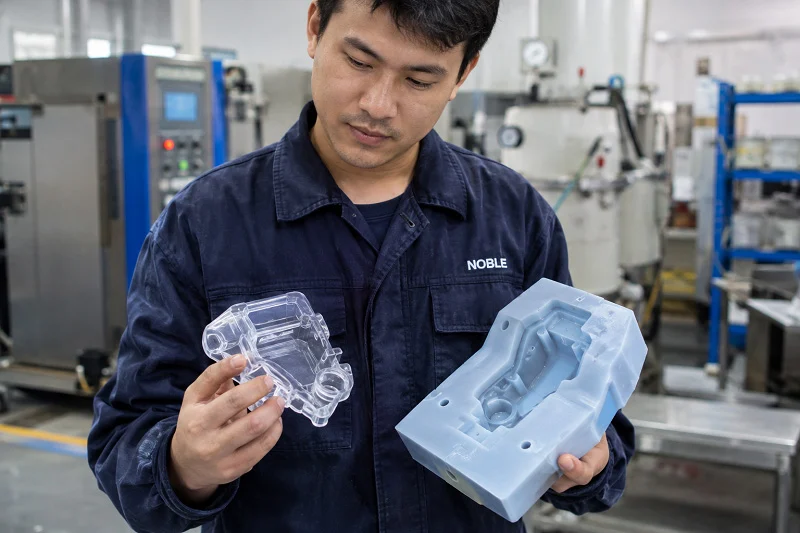
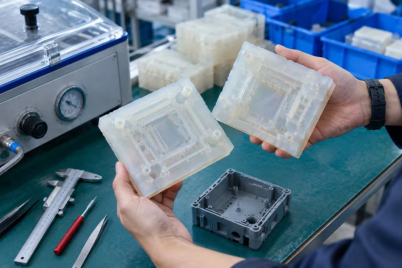
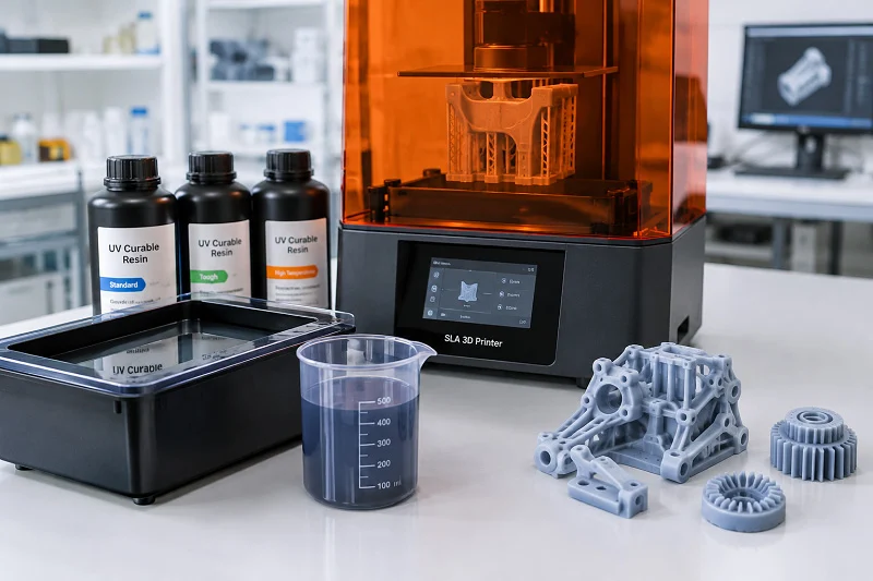
Metal 3D printing brings a different trade-off. SLM and DMLS processes achieve ±0.05 mm tolerances. Post-machining can bring critical features to ±0.025 mm. The real advantage lies in geometric freedom. Internal channels, lattice structures, and organic shapes print directly. Cost barely correlates with complexity. That makes 3D printing ideal for prototypes and low-volume production. For initial concept models, FDM offers the lowest cost but only ±0.2 mm accuracy. SLA and MJF sit in the middle at ±0.05 to ±0.1 mm. The smart approach combines methods. Print the complex near-net shape, then machine the critical surfaces. This hybrid strategy balances cost, precision, and design freedom for precision motion components.
For high-speed motion applications, the manufacturing process directly affects performance. A poorly finished surface creates friction. Friction generates heat. Heat changes dimensions. The cycle repeats. Choosing the right process breaks that cycle before it starts. Process repeatability matters just as much as the initial tolerance. A process that delivers ±0.005 mm once but drifts on the hundredth part fails the precision motion control test. Documented procedures, regular calibration, and statistical monitoring keep processes stable. That stability is what automation systems depend on. Every robotic arm, every positioning stage, every precision motion control loop relies on precision motion components made right the first time and every time.
Design for Manufacturability in Precision Motion Control
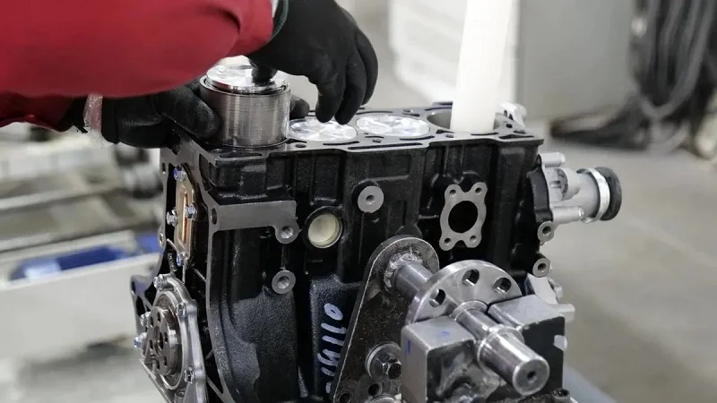
The way you design a part decides if it is easy or hard to make. Good designs cut down on build problems. Bad ones cause endless trouble. Engineers who plan for manufacturing early on save time, money, and headaches.
Designing for Tolerance Stack-Up
Tolerance stack-up in precision motion control happens when many parts add their small errors together. The total gap or fit can ruin how well the system works. Fixing this early stops problems before they start.
GD&T Basics for Precision
Geometric Dimensioning and Tolerancing controls part shape beyond simple size measurements. GD&T tells you about flatness, squareness, and location. It uses datum points to lock in measurements. Feature control frames show machinists what really matters. This method predicts how parts will fit together. For precision motion control systems, this is very important. Meeting tight needs starts with the drawing. A shaft that is round but bent needs GD&T. Simple size tolerances do not catch that.
Material Impact on Tolerances
Different materials can hold different tolerances while keeping precision. Aluminum alloys can reach ±0.025 mm. Stainless steel is around ±0.05 mm. Titanium alloys go to ±0.1 mm because they are hard to machine. Engineering plastics run ±0.1 to ±0.2 mm because they expand with heat. A 300 mm aluminum part grows about 0.07 mm for every 10°C temperature change. Asking for a tolerance tighter than that is impossible. Match your tolerance to what the material naturally does. That saves money and keeps precision motion components working well.
Surface Finish and Functional Performance
Surface finish changes how parts move, seal, and wear. A smooth surface lowers friction. A rough one holds oil. Both have their uses.
Roughness, Friction, and Wear
Rough surfaces create friction that wears down parts. In precision motion components, that wear changes sizes over time. A bearing surface that starts with the right fit may get loose after many cycles. Smoother finishes last longer under load. But too smooth means no oil stays on the surface. Some surfaces need a little texture to hold lubricant. The right finish balances friction while keeping precision.
Specifying Finishes for Sealing and Lubrication
Seals need a certain surface finish to work. Too rough, and the seal wears out fast. Too smooth, and the seal may not grip. Lubrication also depends on finish. Oil needs tiny pockets to stick to. A mirror finish can leave a bearing dry. Choose finishes based on what the part does, not just habit. This helps precision motion control systems last longer between maintenance.
Integrating Assembly and Inspection into Design
The best time to plan for putting parts together and checking them is during design. Waiting until production starts leads to expensive fixes.
Designing for Cleanliness and Contamination Control
These systems really hate dirt. One tiny particle can jam a bearing or scratch a machined surface. Design features that catch dirt are bad. Ones that let dirt fall off are good. Avoid blind holes that collect debris. Add chamfers to guide parts together without scraping. For critical assemblies, design for cleanroom assembly. In precision positioning, cleanliness affects reliability and repeatability. Design for the same process repeatability every time during assembly.
Planning for In-Process and Final Inspection
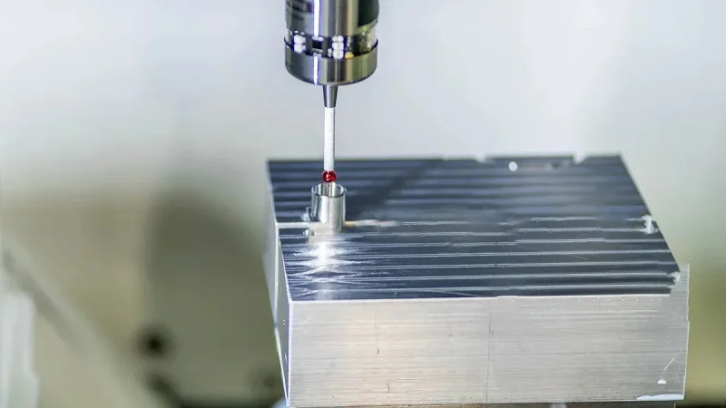
Inspection catches problems early but costs money. The cost grows with how tight the tolerance is. Standard tolerances at ±0.13 mm only need sample checks. The cost multiplier is 1x. Tight tolerances at ±0.025 mm need special tools and controlled temperature. Cost jumps to 3-5x. Ultra-tight at ±0.010 mm requires checking every part and stress relief. Cost hits 8-15x. Plan inspection points at key steps. In-process checks catch drift. Final inspection checks the whole assembly. For precision motion control, automatic inspection systems measure every part the same way. That consistency improves process repeatability and accuracy. Precision requires traceability when a system fails in the field.
Overcoming Production Challenges for Precision Motion Components
Making precision motion components is rarely smooth sailing. Global trade disruptions, volatile transportation costs, and supply-demand imbalances stall production. These factors make long-term cost forecasting difficult and lead times unpredictable. The solution for many companies is reshoring with a vertically integrated, single-source domestic manufacturer. This approach reduces exposure to international disruptions, provides more predictable lead times, and lowers freight complexity and cost.
Balancing Cost, Lead Time, and Quality
Every production decision involves trade-offs. Push cost down too hard, and quality suffers. Compress lead times too much, and errors creep in. The key is understanding what drives costs in the first place.
Key Cost Drivers in Precision Manufacturing
Design complexity tops the list. A part requiring 5-axis machining costs far more than one that fits on a 3-axis machine. Material choice matters too. Harder metals like titanium wear tools faster and slow production. Tight tolerances and thin walls add machining time and inspection requirements. Small production quantities spread setup costs thin, raising per-unit prices. Finishing requirements, such as special surface treatments, add yet another layer of expense.
Strategies for Cost Reduction Without Sacrificing Precision
Lean manufacturing offers a proven path. Companies typically reduce operational costs by 20–30% in the first year by eliminating waste. Supply chain optimization helps as well. Consolidating suppliers and negotiating contracts regularly can boost profitability by up to 23%. Automation lowers labor costs and reduces defects. But never switch to cheaper suppliers at the expense of raw material quality. Instead, negotiate better terms with reliable vendors. Simplify designs where possible. Use standard hole and thread sizes. Round internal corners to at least one-third of cavity depth. Review tolerance requirements for necessity. These small changes improve manufacturing efficiency without compromising precision motion control.
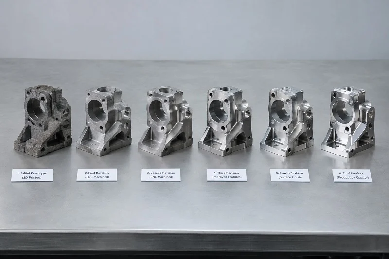
Ensuring Scalability from Prototype to Production
A prototype that works beautifully in the lab often fails in production. The gap between one part and ten thousand parts is enormous. Planning for scale from day one prevents painful surprises.
Process Validation and Qualification
Before ramping up volume, validate every step. Document the process parameters that produce acceptable parts. Establish baseline metrics for defect rates, return rates, and critical-to-quality parameters. Conduct risk assessments using FMEA before altering materials, suppliers, or methods. This identifies quality vulnerabilities before they become expensive problems. Maintain documentation and traceability from raw input to finished product. When something goes wrong, you need to know exactly where and why.
Supply Chain and Reshoring Considerations
Reshoring changes how companies pick suppliers. The traditional approach focused on lowest-cost sourcing. The reshoring-driven approach looks at total value. That means considering operational risk, responsiveness, quality consistency, and engineering support. Suppliers become strategic engineering partners rather than mere component vendors. Key selection criteria shift from price to technical ability, partnership, and long-term reliability. The benefits include faster prototyping cycles, improved supply chain predictability, and easier onsite collaboration. Domestic engineering support shortens development timelines and provides greater insight into production schedules.
Implementing Robust Quality Control Systems
Quality control is not a single checkpoint. It is a continuous process that runs alongside production. The best systems catch problems before they become defects.
In-Process Monitoring vs. Final Inspection
In-process monitoring detects variation before defective products are produced. It is proactive quality control. Final inspection checks products after they are made. It is reactive. The difference matters. In-process monitoring delivers 20–40% defect reductions. Inspection-based approaches cannot achieve this. For precision motion control applications, catching a drift early saves thousands of dollars in rework and scrap. Frequent quality checks at multiple production stages catch defects early and prevent costly rework.
Statistical Process Control (SPC) for Consistency
SPC uses control charts to monitor process stability. Start by defining critical parameters. Identify the process variables with the highest correlation to defects. Collect 20–25 subgroups from a stable process to establish baseline data. Calculate upper and lower control limits from process data, not engineering specifications. Choose the right chart type for your data structure. X-bar R charts work for continuous data. P-charts suit attribute data. Configure alert rules using Western Electric or Nelson Rules. Link every out-of-control signal to a corrective action workflow. Measure capability using Cp and Cpk. A Cpk below 1.00 means the process is producing defects. A Cpk between 1.33 and 1.67 meets the industry benchmark for most regulated industries. Above 1.67 indicates Six Sigma-level performance. This systematic approach ensures process repeatability and accuracy across every batch. For precision motion components, consistency is everything. Automation systems depend on parts that perform identically every cycle. SPC delivers that reliability.
Partnering with NOBLE for Precision Motion Components

When you need parts that move with exactness, pick a partner who sees the big picture. NOBLE combines design, prototyping, and assembly in one place. That means less passing of work, fewer delays, and less risk of mistakes. For teams handling reshoring, this single-source plan helps a lot.
Our Comprehensive Manufacturing Capabilities
NOBLE works with both metal and plastic. That range is important because precision motion control systems often use mixed materials. A steel guide rail may go with a polymer bushing. Aluminum housings may hold ceramic bearings. One partner who makes all of them saves you from managing many suppliers.
Expertise in Metal and Plastic Machining
Our shops do CNC machining, grinding, and lapping for metals. We also work with engineered plastics like PEEK, acetal, and Torlon. Each material needs different tools, speeds, and cooling methods. We know these details. That knowledge produces parts that keep their tolerances and work reliably. When you need precision motion control parts that fit together just right, that skill matters.
From Design and Prototyping to Full-Scale Assembly
The process starts with your idea. Our engineers check the design for how easy it is to make. We find tolerance stack-up problems before they turn costly. Then we make prototypes to test the method. After we confirm it works, we move to full production. Assembly happens in our own shop too. That means your parts come as finished assemblies, not separate pieces. This makes your supply chain simpler and shortens your lead times.
Certifications and Quality Assurance
Certifications show that a maker cares about quality. NOBLE has two important ones. Each one has a different job, and together they cover many uses.
ISO 9001:2015 for Quality Management
This standard focuses on consistent quality in all work. As of 2024, over 1.47 million groups worldwide have this certification. Manufacturing areas like metal products and machinery are among the top industries for it. The standard is based on seven ideas: customer focus, leadership, engaging people, process approach, improvement, using facts to make decisions, and managing relationships. For you, that means written procedures, regular checks, and a system that spots problems early. The result is fewer defects, better on-time delivery, and faster handling of complaints.
ISO 13485:2016 for Medical Device Manufacturing
Medical devices need even tighter controls. ISO 13485 makes sure parts meet the highest safety and risk standards. Think of stepper linear actuators in automatic pipetting systems or robotic surgery tools. The standard requires process validation to keep production the same across batches. It also demands full traceability, so every part can be tracked from raw material to delivery. Risk management is part of the process, finding possible failures before they affect patients. For medical uses, this certification is a must.
A Single Source for Complex Projects
Complex projects need more than just machining ability. They need teamwork and clear communication.
Collaborative Engineering Support
Our engineers work with yours. We advise on materials, tolerances, and assembly methods. That teamwork often finds ways to boost performance and lower costs. You get a partner who thinks about the whole system, not just the single part.
Streamlined Project Management and Communication
One person handles your project from start to finish. No running after different departments. No waiting for news from several vendors. Just clear, steady communication. That efficiency keeps your schedule on track and your team in the loop. For precision motion control systems, this partnership gives high reliability and repeatability. When every part works together smoothly, your system works better. That is what we try for with every project.
Choosing precision motion components comes down to three interacting factors: material properties, manufacturing process capabilities, and production constraints. No universal solution exists. Your specific application, volume, and environment determine the right path.
Reshoring adds another layer. Partner selection now hinges on technical capabilities, quality systems, engineering support, and geographic proximity. These criteria ensure supply chain resilience and consistent delivery.
| Selection Criteria | Why It Matters |
| Technical capabilities | Matches equipment to precision motion control needs |
| Quality systems | ISO 9001 baseline assurance |
| Engineering support | Design collaboration improves precision motion control |
| Geographic proximity | Redundancy and faster response |
The right partner delivers repeatability and efficiency across every batch. Use this guide as your starting point. Consult experts to optimize your design for precision motion control performance. Your next project deserves that investment.
FAQs on Precision Motion Components
How do I choose between steel, aluminum, and plastic for my precision motion components?
Think about load, weight, and environment. Steel handles heavy loads best. Aluminum offers lighter weight with good strength. Plastics reduce friction and need no lubrication. Match the material to your operating conditions. Consider temperature swings and moisture exposure too.
What tolerance can I realistically expect from CNC machining?
Standard CNC machining holds ±0.001 inches. High-end machines reach ±0.0002 inches. Your part geometry and material affect these numbers. Plastics move more with temperature changes. Ask your machinist what they can hold consistently, not just once.
When should I use grinding instead of standard machining?
Choose grinding when you need exceptional flatness or surface finish. Double disk grinding produces parallel surfaces with sub-micron accuracy. Lapping goes even further for optical-grade finishes. If your precision motion control system needs smooth, low-friction surfaces, grinding delivers results standard cutting tools cannot match.
Is 3D printing suitable for production parts?
Yes, with limits. Metal 3D printing achieves ±0.05 mm tolerances. Post-machining tightens critical features to ±0.025 mm. The real win is geometric freedom. Complex internal channels print directly. For prototypes, it beats waiting weeks for tooling. For high-volume runs, traditional machining often costs less per part.
How does reshoring affect my supplier choices?
Reshoring shifts focus from lowest price to total value. You want a partner with technical skills, quality systems, and engineering support. Geographic proximity means faster response and easier collaboration. Look for a single-source manufacturer who handles design, prototyping, and assembly. That simplifies your supply chain and cuts risk.
What does ISO 9001:2015 certification actually guarantee?
It guarantees a documented quality management system. The standard requires written procedures, regular audits, and corrective action workflows. Over 1.47 million organizations hold this certification. For you, it means fewer defects and better on-time delivery. It does not guarantee perfection, but it shows a commitment to steady quality.
How do I plan for inspection costs in my budget?
Tolerance drives inspection cost. Standard tolerances at ±0.13 mm need only sample checks. Tight tolerances at ±0.025 mm require special tools and controlled temperature. Ultra-tight at ±0.010 mm demands checking every part. Build these costs into your quote early. Surprise inspection bills derail projects.
What is the best way to prevent tolerance stack-up problems?
Use GD&T from the start. Geometric Dimensioning and Tolerancing controls shape, not just size. It predicts how parts fit together before you cut metal. Match tolerances to what your material can naturally hold. Aluminum reaches ±0.025 mm. Titanium struggles past ±0.1 mm. Design within those limits.