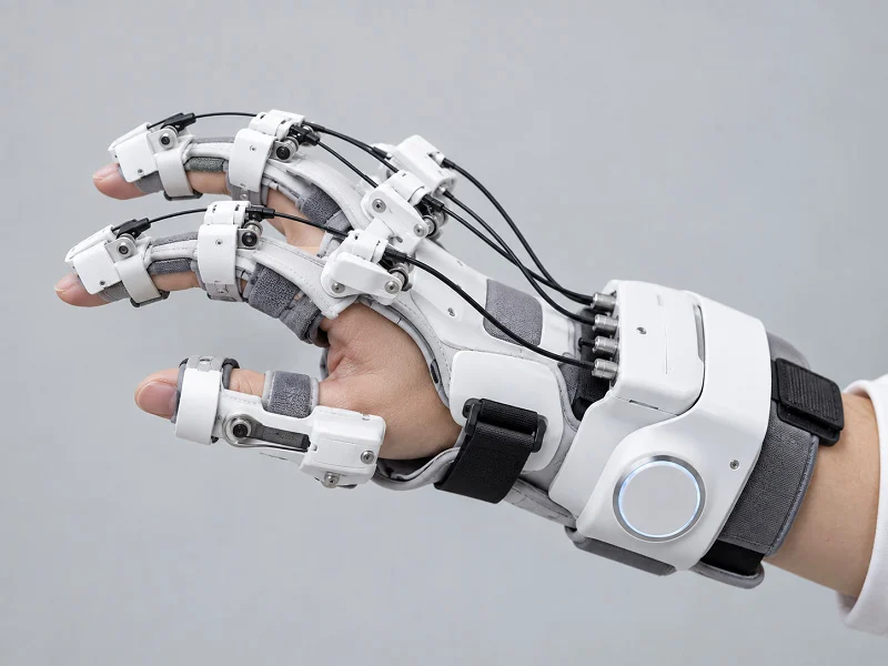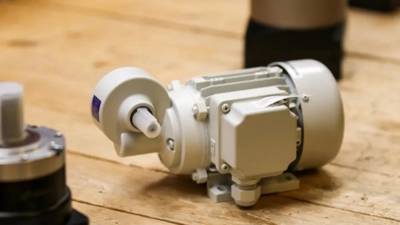
A robot joint is the moving link between two rigid parts. It steers motion and direction in a robotic arm. The robot joint housing wraps around the bearings, motors, encoders, and gearboxes inside. It keeps them aligned, clean, and safe. That shell matters more than it looks. Fact.MR valued the global robot arms market at about USD 22.74 billion in 2025, so the stakes are high. Good robot joint design protects precision in industrial arms and cobots. The same care carries into every integrated robot joint and robot joint module. Each robot joint application depends on it.
Robot Joint Design and Housing Considerations

Every robot joint design starts with a simple question: what forces will this joint face? The answers shape everything about the robot joint housing. Backlash, stiffness, weight, and thermal management all pull on robot joint housing design decisions. Get these wrong, and your integrated robot joint will never hold position accurately.
Load-Bearing and Stiffness Needs
The housing acts as the structural backbone. It keeps things aligned and stiff when under load. A thin robot joint housing with a stiff reducer inside makes the whole joint soft. To find where the give comes from, measure the reducer alone and then again inside the assembled joint. The difference shows how much the bearings, housing, and fasteners add to it.
Stiffness vs. Weight Balance
Stiffness must be balanced against weight. A heavy arm wastes energy and limits how much it can lift. The goal is high stiffness without too much mass. This push and pull guides material choices and wall thickness in manufacturing.
Mounting Interface Geometry
Mounting faces need to be flat and square. Any tilt here causes misalignment later. In a low-profile robot joint, the mounting flange often also moves heat. That double job makes shape even more important.
Tolerance and Fit Planning
Fit tells you how the bearing sits in the bore. Geometry tells you where that bearing sits compared to everything else. Two bearing bores can each meet their size specs but still be out of line. That’s why robot joint design must include shape needs, not just size limits.
Bearing and Gear Seating
For harmonic drive joint modules, bearing journals need to be centered within 0.006 mm. This stops early gear tooth wear and backlash. Bore-to-face squareness should stay within 0.005 mm total indicator reading to avoid pinching the bearing race. Dowel pin patterns need true position within plus or minus 0.008 mm. Planetary gear center-to-center distances should hold to plus or minus 0.006 mm. These aren’t just ideas. They make the difference between a joint that repeats and one that drifts.
Thermal Expansion Allowances
Heat changes everything. A robot joint housing that’s perfect at 20°C may seize at 70°C. Thermal cycles during machining pre-age the material. This keeps it stable across thousands of temperature changes. For cold-storage or foundry robots, low-CTE materials keep micron-level centering from 0°C to 70°C.
| Joint | Thermal Consideration | Material Selection |
| J1 (Base) | High constant torque | 20CrMnTi, case-carburized |
| J2 (Shoulder) | Accurate positioning under growth | 42CrMo, surface-hardened |
| J3 (Elbow) | Faster response lowers heat | 42CrMo, 54–57 HRC |
| J4 (Wrist Rotation) | Very little heat | 42CrMo or 20CrMnTi |
| J5 (Wrist Pitch) | Highest precision needed | 42CrMo or titanium |
| J6 (Tool) | Weight matters | Aluminum, titanium, or nitrided steel |
Component and Cable Integration
An integrated robot joint packs a motor, encoder, brake, gear set, and servo drive into one shell. That’s a lot of electrical, heat, and mechanical mixing. Every part fights for space.
Motor, Encoder, and Sensor Placement
Motor placement affects how heat leaves. Encoders need clean signal paths. Sensors must survive vibration. The housing shape must fit all of them without hurting alignment. Complex fin patterns machined into the robot joint housing add surface area for cooling. Fins can be angled to match airflow where the robot is installed.
Sealing and Cable Routing
Cables are a hidden challenge. Gather loose wires and wrap them in a split sheath. Fasten the sheath at both ends so wires stay in place during rotation. Make a service loop of extra cable for full arm motion without pulling. Loose wires get caught and yanked when parts move past each other. Plan for extra wire when the part is pulled in, then shape that extra into a neat loop. Protect bundled wires with expandable or spiral sheathing near pinch points. Group motor power and encoder wires together and fasten them to the motors.
Sealing keeps dirt out. Heat removal pushes heat out. Cable routing lets everything move freely. These three challenges repeat in every industrial arm and cobot. Solve them early, and your robot joint mechanical parts will work for years.
Materials for Robot Joint Housing
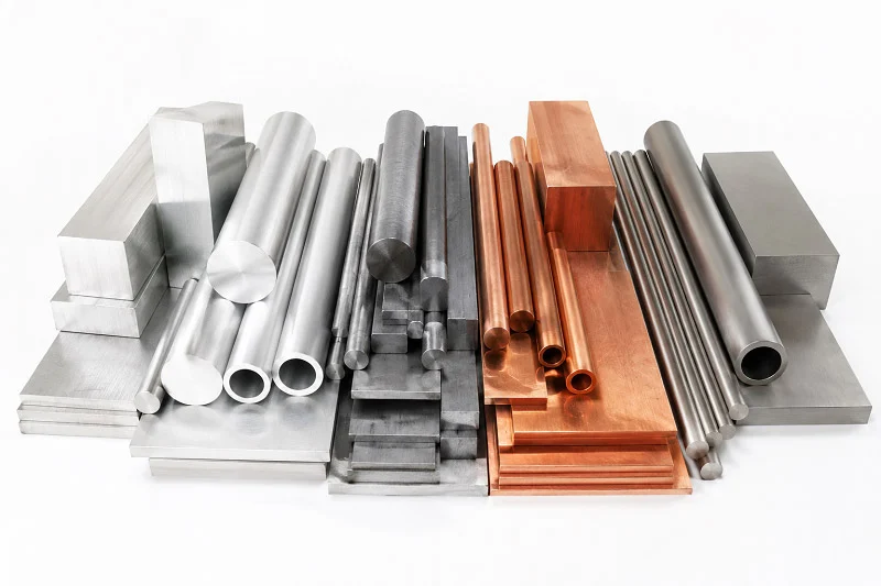
The material you pick for a robot joint housing changes its weight, stiffness, heat handling, and cost. Every choice comes with trade-offs that affect the whole manufacturing process. The best match depends on the load and the environment the joint will face.
Aluminum Alloys
Aluminum is the most common pick for robot joint parts. It is light, easy to machine, and moves heat away so motors run cooler. Both 6061 and 7075 anodize well, which makes them good for many industrial uses.
6061 vs. 7075 Alloys
6061-T6 is the everyday workhorse grade. It is easy to machine, weld, and anodize. It costs less and works well for low-load joints. But it has limits. A shell made of 6061 will wear out faster under repeated heavy loads. For joints that cycle many times per minute, that is a real risk.
7075-T6 gives you better performance. It is about 66% stronger in fatigue. The table below shows the numbers.
| Property | 6061-T6 | 7075-T6 | Difference |
| Fatigue Strength (10^8 cycles) | 96 MPa (14 ksi) | 159 MPa (23 ksi) | 7075-T6 is 66% higher |
7075 beats 6061 in fatigue resistance because of its stronger grain structure and lower chance of micro-cracking, which makes it a better fit for cyclic loading in these parts.
That extra strength comes with trade-offs. 7075 is harder to machine. Tool wear goes up. It is also harder to weld and costs more. But for a robot joint module that cycles many times a day, 7075 is worth the extra cost. The longer life makes up for the higher material price.
Anodizing Compatibility
Both alloys anodize well. But 7075 needs more care during the process. Type II anodizing adds standard corrosion protection. Type III hard coat adds serious wear resistance. A 7075 component with hard anodizing resists fretting under the constant vibration of a robot joint module. Hard coat also traps less heat, which helps thermal management.
Steel and Stainless Steel
Steel brings stiffness that aluminum cannot match. It is heavier, but sometimes precision matters more than weight. Steel also handles higher temperatures without losing strength.
Corrosion Trade-Offs
Steel rusts easily in wet or chemical environments. Stainless steel fixes that but costs more and machines slower. For a foundry joint part that sees heat and moisture, stainless pays off quickly. For a clean-room arm, coated steel may be enough. Coatings like electroless nickel add cost but widen the useful range of cheaper steels.
Strength and Wear Resistance
Steel parts excel in high-torque base joints like J1 and J2. Case-hardened steels like 20CrMnTi resist denting at bolt interfaces. The surface stays hard while the core stays tough. That combination is hard to beat for heavy-duty use. For high-wear areas, nitrided steel adds extra surface hardness without distortion.
Plastics and Composites
Plastics cut weight a lot. They work best in low-torque or collaborative robots where mass matters most. They also dampen vibration naturally, which helps position stability.
PEEK and Nylon Uses
PEEK handles higher heat than most plastics. It resists chemicals and wears slowly over time. Nylon costs less but absorbs moisture, which changes dimensions. Use PEEK for sealing rings and bushings inside the joint. Use nylon for outer covers that carry no load. Nylon grades with glass fill improve stiffness but reduce impact resistance.
Carbon-Fiber-Reinforced Options
Carbon-fiber composites offer stiffness close to aluminum at half the weight. They do not conduct heat well, so thermal management gets harder. They also cost more to produce and need careful mold design. For a high-speed cobot arm, carbon fiber in certain sections can lower inertia a lot. Each material choice guides the rest of manufacturing, from machining speeds to surface treatment.
Prototyping and Testing Robot Joint Housing
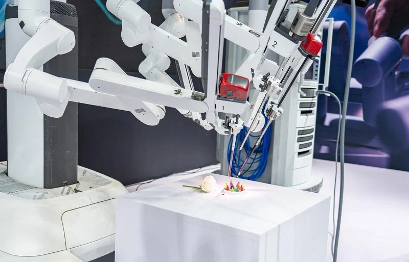
Prototyping takes your robot joint design from an idea to a real part. It helps you find problems before you spend money on production tools. Finding a problem early saves weeks of time and thousands of dollars. A good prototyping stage is what makes a part reliable instead of one that breaks in the field.
Rapid Prototyping Methods
In prototyping, speed is important. Two methods are the most common. Each one works best at a different stage.
CNC vs. 3D-Printed Prototypes
CNC prototypes are made from real metal. Their stiffness and heat behavior match the final part. For an integrated robot joint, that information is key. You can’t guess how the robot joint housing acts under load. You need real numbers. The bearing seats, gear journals, and mounting faces all need metal properties.
3D printing is good for checking shape, but not for load tests. Plastic bends in a different way than metal. The results will not be right. But printing is fast and cheap. You can check cable routing and shape in one day. For joint module parts like bearing seats, always use CNC. Plastic tolerances are too loose.
Functional and Durability Testing
A robot joint housing that fits must also work under load. Functional testing proves that. Durability testing shows it will last through years of use.
Fit and Form Checks
Fit checks test how parts fit together. Put a bearing in the bore. Spin it. Feel for any drag. Try the motor. Does it slide in smoothly? Check the gear. Does it sit all the way in? These hands-on tests show hidden design problems. A 30-minute fit check can save weeks later.
Form checks look at the whole assembly. Do cables fit through the channels? Do mounting holes line up? Does the encoder wire reach without stretching? Simple checks stop expensive rework.
Load and Torque Tests
Mount robot joint modules on a test stand. Apply torque little by little. Measure deflection at each step. Compare it to stiffness targets. The results tell you if the housing is stiff enough for precise work.
Backlash testing is part of this step. Lock the output. Measure how much the input moves. For an integrated robot joint module, keep backlash under 1 arcmin. Higher numbers mean the robot joint housing bends too much. Fix it with thicker walls or better bearing support. A housing that bends throws off the gear mesh and wears the teeth faster.
Vibration and Fatigue Tests
Vibration testing finds natural frequencies. A housing that shakes at operating speed will fail early. Add ribbing or thicken walls to push frequencies higher.
Fatigue testing runs a robot joint module through millions of cycles. This shows if your material choice holds up. Small cracks near bolt holes show up here. The test shows the expected life for robot joint modules. Use this data to set maintenance intervals.
Design Iteration and Validation
Testing makes data. Data leads to changes. That feedback loop makes prototyping worth the effort.
Test Data Feedback Loops
Write down every result. Backlash, stiffness, temperature rise. Compare each one to design targets. If a number misses the mark, change the robot joint housing.
Add wall thickness. Adjust a bearing fit. Machine a new prototype. Test again. Each loop makes the design better. Three to five rounds is normal for a complex housing. The data tells you what to fix and when to stop.
Design Freeze Criteria
Set a clear stop point before you start. Define what success looks like. Example criteria: backlash under 1 arcmin, no failures in 10 million cycles, stiffness above a target value. Write these down early.
Once the prototype meets all targets, freeze the design. Lock the 3D model. Move to manufacturing. Work with an experienced shop. NOBLE is a leading manufacturing company in China. They handle prototyping and full production. Their machining expertise delivers CNC parts that match final specs from the first prototype. That cuts iteration time and builds confidence in your robot joint housing.
Precision Machining of Robot Joint Housing

Machining turns a raw block into a finished robot joint housing. This stage decides whether bearings sit true and gears mesh clean. For metal robot joint housings, CNC milling and turning carry most of the work. Plastic or low-volume housings can come from injection molding or 3D printing instead. Those routes skip the chips, but they trade away stiffness and tight tolerances. Metal parts stay the standard for industrial arms.
CNC Milling and Turning
Milling cuts pockets, faces, and bolt patterns. Turning shapes round bores and flanges. Most joint housings need both. A machined blank often starts on a lathe, then moves to a mill for the side features. Each setup adds a chance for error, so shops plan the order with care.
Multi-Axis Machining Benefits
Five-axis machines change the game for complex parts. The tool or the part tilts, so the cutter reaches angles that a three-axis setup cannot touch. Here is what that buys you:
- Fewer setups, since all sides get machined in one clamping.
- Better surface finish, because the tool holds an optimal angle.
- Tighter tolerances, since less repositioning means less drift.
- Support for curved, angled, or organic features.
- Longer tool life, because smart angles cut stress and heat.
Deep pockets and angled holes are the real test. A three-axis machine needs long tools that flex and chatter. Five-axis work tilts the part so a short, rigid tool can reach inside. That keeps walls stable and finishes clean. Fewer setups also cut datum transfer risk. Mounting holes, side ports, and a sealing face all stay in one coordinate system. That matters when a bolt pattern must line up with an internal pocket.
Fixturing Thin Walls
Thin walls move when you clamp them. Too much pressure and the bore goes oval. Too little and the part lifts during the cut. Soft jaws machined to the part profile spread the load. Support blocks behind the wall add rigidity without marking the surface. Light finishing passes remove the last bit of material with minimal force. A well-planned fixture protects the geometry that the design demands.
Drilling, Boring, and Tapping
Holes look simple until you check position. A motor flange with holes off by a few hundredths will not bolt down flat. Boring then sizes the bore to its final fit. Tapping cuts the threads that hold fasteners under vibration.
Hole Position Accuracy
Position tolerance depends on the joint’s job. The table below shows common levels.
| Precision Level | Mounting Hole Position Accuracy | Application |
| Standard | ±0.05 mm | General robot joint applications |
| High | ±0.02 mm | High-precision robot joint applications |
| Ultra-high | ±0.01 mm | Ultra-precision robot joint applications |
Concentricity between a mounting hole and the bearing bore should stay within 0.02 mm TIR. Hole diameter accuracy holds within ±0.05 mm. Tapped holes follow thread class 6H per ISO 965.
Thread Quality for Fasteners
Threads carry the clamp load that keeps a robot joint module together. A shallow or torn thread strips under vibration. Sharp taps, correct drill sizes, and proper lubrication all protect thread form. Check thread depth and gauge every critical hole. A stripped fastener hole means a scrapped part, not a quick fix.
Surface Finish and Dimensional Control
Bearing seats need smooth surfaces. Roughness drives wear and noise. Tool choice and cutting speed set the finish. In-process checks catch drift before a batch goes bad.
Tool Selection and Speeds
Sharp carbide tools with the right coating cut aluminum clean. Higher spindle speeds and moderate feeds leave a fine finish. Dull tools smear the surface and raise roughness. For steel, slower speeds and rigid setups control heat. Coolant keeps temperatures steady so dimensions hold.
In-Process Measurement
Measure while the part is still on the machine. Probing checks bore size and position before unclamping. That feedback lets the operator adjust offsets in real time. Catching a drift early saves a whole batch. This habit is central to precision manufacturing, and it separates a reliable shop from a risky one.
Bearing or bushing seats commonly require Ra 0.4 to 0.8 µm, achieved through grinding or precision turning.
Those seats anchor every robot joint module, so the finish spec is not optional. Good manufacturing processes pair the right tool with a measurement loop. That combination holds tolerances across thousands of parts. Skilled manufacturing keeps robot joint modules running true for years.
Surface Treatment of Robot Joint Housing
Surface treatment protects a robot joint housing from rust, wear, and dirt. But coatings can change the size of the part. Bearing bores and sealing faces need to be masked off. The right finish keeps the joint working smoothly for many years.
Anodizing and Conversion Coatings
Anodizing grows an oxide layer right into the aluminum surface. This layer fights off rust and makes the surface harder. It is the normal finish for most housings.
Type II vs. Type III Anodizing
Type II anodizing gives good protection against rust and can take dye. For a clean space, Type II works just fine. It adds a fair amount of wear resistance.
Type III hard anodizing is not the same. It builds a thicker, denser oxide layer. Its hardness reaches 600 to 700 HV. Raw 6061-T6 is only around 95 HV. That big jump makes a real difference. Type III works well for sliding and rotating surfaces. You can add PTFE to it to make a low-friction surface. Motion becomes smoother and easier to repeat. For a robot joint module that moves every day, Type III is the better pick.
Corrosion and Wear Benefits
Raw aluminum has only moderate resistance to rust. Type II rates as excellent. Type III adds extreme wear resistance. An untreated robot joint housing gets scratched and pitted in a factory. A hard-anodized one stands up to cleaning chemicals and factory dirt.
Chromate conversion coating is another option. It makes an ultra-thin protective film. That film keeps electricity flowing. It also helps paint stick. Type I hexavalent chromate fits old aerospace needs. Type II trivalent clear chem film meets RoHS and REACH rules. Use it when anodizing adds too much thickness for your fits.
Painting, Powder Coating, and Plating
Some housings get painted or powder coated instead of anodized. These methods add thicker layers. They change dimensions more than anodizing does.
Coating Thickness Control
Precision bores have tight tolerances. An H6 bore cannot take much coating. Type III hard anodizing adds 25 to 75 μm. That shrinks the bore diameter by about half that amount. Too much, and the bearing will not fit. Preload gets lost.
Three methods fix this. Mask the bearing bores before coating. Order oversized bores so the final size stays in tolerance. Keep hard anodizing on outside surfaces only. Manufacturing teams often use all three at once. That is normal practice for precision parts.
Masking Critical Surfaces
Bearing seats, sealing surfaces, and threaded holes all need masking. If coating gets into a thread, fasteners will not seat right. If it builds up on a seal face, the O-ring leaks. Masking tape or silicone plugs block the coating. Remove them after treatment. Check every surface before assembly.
Deburring and Edge Preparation
Sharp edges cut wires and catch gloves. They create stress points and crack over time. Deburring removes those risks.
Manual vs. Automated Deburring
Manual deburring uses files, scrapers, and abrasive pads. A skilled worker can reach every hidden edge. It works well for low volumes. Automated deburring uses brushes or tumbling media. It is faster and more consistent. For high-volume robot joint modules, automation wins. Every part comes out the same.
Edge Break Specifications
Edges need a small break. Common specs call for 0.1 to 0.5 mm. That removes burrs without changing the shape. Specify breaks on all outside edges. Leave internal bearing edges sharp unless drawings say otherwise. A clear spec stops fights between design and the shop floor.
Surface treatment takes a machined housing and gets it ready for service. The right coating keeps dirt out and stops rust. Mask the right surfaces. Pick the right anodizing type. Break the edges. A robot joint module with good surface treatment runs longer and needs fewer rebuilds.
Quality Inspection of Robot Joint Housing

Inspection proves that a robot joint housing meets its design tolerances and surface needs. You can make a great part and still send out a bad one. Only measuring tells the truth.
Dimensional Inspection Methods
A coordinate measuring machine, or CMM, measures parts in three dimensions. It has a moving arm, a probe, and a computer. The probe touches points on the part. The machine records each point as X, Y, and Z coordinates. Those points form a 3D point cloud. Software compares that cloud to the design model.
CMM and Optical Measurement
For a bolt pattern with a true position tolerance, checking X and Y alone is not enough. Each hole’s location matters compared to other holes and to set datums. So the CMM measures the true position of each hole’s axis. It checks that the axis falls inside a needed cylinder-shaped tolerance zone. Optical comparators do the same for smaller features.
GD&T Verification
Here is how the math works. Measure the real center of each hole. Record its X and Y against the datum reference frame. Then find the differences: dx equals actual X minus nominal X, and dy equals actual Y minus nominal Y. The true position formula is P = 2 × √(dx² + dy²). That gives the smallest cylinder diameter centered on the basic location that holds the actual hole axis.
Position at MMC allows bonus tolerance as the feature leaves its maximum material size. A hole specified at MMC of 0.266 in. that comes out at 0.270 in. gets a bonus of 0.004 in. The allowed position grows from 0.010 in. to 0.014 in. This makes sense: a larger hole can accept more position error and still fit.
Material and Coating Verification
Hardness testing checks that heat treatment worked. Different methods fit different needs.
| Hardness Testing Method | How It Helps Robot Joint Housing Steel Parts |
| Brinell | Checks hardness in high‑temperature parts like forgings and heat‑treated parts |
| Rockwell | Best for hardened steel and heat‑treated alloys |
| Vickers | Good for case depth and hardness changes |
| Knoop | Great for very small marks like coatings and heat‑affected zones |
Hardness and Composition Checks
Rockwell works for hardened steel and heat‑treated alloys. Vickers shows case depth and hardness changes. Knoop works in coatings and weld areas. Composition checks confirm the alloy matches the mill certificate.
Coating Adhesion Testing
Coatings must stick. A tape test or scratch test shows if anodizing or plating bonds to the base metal. Poor bonding means early rust.
Documentation and Traceability
Traceability matters most in safety‑critical and medical‑related robots. Auditors want full lot tracking from raw‑material mill certificates to final inspection. That includes material tracking with lot numbers through the finished part. Batch tracking covers mill certificate checks, chemical makeup, and mechanical property checks. Full raw material certification and lot tracking finish the circle.
Inspection Reports
Every key dimension gets recorded. Reports list measured values next to nominal and tolerance.
Lot and Serial Tracking
Serial numbers tie each robot joint module to its inspection data. If a failure happens in the field, you can trace it back.
Good inspection supports high accuracy and reliability in every robot joint module. It also keeps your manufacturing records clean and your manufacturing reputation strong.
Assembly Integration of Integrated Robot Joint Modules

An integrated robot joint holds the motor, gear set, encoder, brake, and servo drive in one shell. Each part must fit in the right way. Assembly keeps the alignment, preload, and sealing that early design and machining steps set. A mistake here ruins all that careful work.
Bearing and Gear Installation
Bearings and gears move power from the motor to the arm. They must sit straight inside the robot joint housing.
Press-Fit and Thermal Fit Methods
A press-fit uses steady force to push the bearing into its hole. The robot joint housing wall must hold the bore without bending. Thermal fit is different. Heat the housing or cool the bearing. The parts then slide together without force. For harmonic drive joint modules, thermal fits are common. They prevent surface damage from pressing. Even temperature is very important. Uneven heat bends the bore and ruins the fit.
Preload Adjustment
Bearings need the right preload. Too much preload causes drag and heat. Too little makes the joint wobble. Adjust preload with shims or a threaded nut. Measure turning torque during adjustment. Stop when the torque matches the spec. This step makes each robot joint module feel the same. The integrated robot joint needs it for smooth motion.
Motor and Sensor Integration
The motor gives torque. The sensor reports position. They must work together without electrical noise.
Alignment Procedures
The motor shaft must line up with the gear input. Misalignment causes shaking and noise. Use a dial indicator. Check runout at the coupling. Keep it within the gear maker’s spec. For precision low-profile strain wave gearing, even a few microns of offset lower gear life. Go slowly here.
Wiring and Connector Routing
Wires carry power and data. Route them to avoid pinching and electrical noise. Shielded cables protect encoder signals from interference.
| Shield Type | EMI Protection | Flex Suitability | Torsion Suitability | Best For |
| Foil (aluminum/mylar) | Good (90%+ coverage) | Poor — cracks in <100K cycles | Not suitable | Fixed installation only |
| Braided (tinned copper) | Very Good (85–95% coverage) | Good — survives 5M+ cycles | Moderate — limited torsion tolerance | Drag chains, linear flex |
| Spiral-Wound (copper) | Good (70–85% coverage) | Good — 3M+ cycles | Excellent — accommodates twist | Robot wrist joints, rotary axes |
| Braided + Foil (combo) | Excellent (>95% coverage) | Moderate — foil limits flex life | Poor — foil cracks under torsion | High-EMI environments, fixed-to-minimal flex |
For integrated robot joint modules, braided shields balance EMI protection with bend life. Spiral-wound shields handle twisting in wrist joints. Connect shields at both cable ends. A loose shield works like an antenna. Keep power cables at least 50 mm away from signal cables inside the arm. Cross them at 90° if they must meet. Joint module parts like the motor and encoder share the same space. Clean wiring saves troubleshooting time later.
Final Testing and Sealing
The last step checks that everything works. Every joint module part must pass before leaving the line.
Leak and Seal Checks
The robot joint housing must stay sealed. Dirt destroys bearings. Moisture shorts electronics. Apply light vacuum pressure. Watch for pressure drop. Use soap solution at seals. Check O-rings for correct seating. Any leak means rework.
Joint Function Verification
Run the joint through full motion. Check for smooth operation. Measure torque output. Make sure encoder feedback matches commanded position. Listen for strange noise. Vibration at a certain speed may mean bearing misalignment. Write down results for tracking. These tests confirm different robot joint modules meet their targets before shipping. A fully tested integrated robot joint is ready for final arm assembly.
Assembly ties everything together. Good manufacturing processes keep the precision from design and production. Each integrated robot joint must leave the line reliable.
Why NOBLE for Robot Joint Housing Manufacturing
Picking a manufacturing partner for a robot joint housing is an important decision. You need a shop that works with metal and plastic, keeps tight tolerances, and knows the whole build. NOBLE is a good fit for that. They focus on robotic parts and bring both materials and processes under one roof.
Metal and Plastic Processing Expertise
Capabilities Across Materials
NOBLE machines aluminum, steel, stainless steel, and engineering plastics. That range matters because a single integrated robot joint often uses different materials. The robot joint housing might be aluminum, the bearing seats steel, and the seals PEEK. One shop that handles all three cuts lead times and stops blame between vendors.
Precision Machining and Finishing
Their shop runs multi-axis CNC equipment and controls surface finish on bearing bores. Anodizing, plating, and deburring happen in-house or through trusted partners. That control protects the fits you designed. It also keeps the manufacturability of the whole assembly in view from the first cut to the last coat.
Certifications and Quality Standards
ISO 9001:2015 Quality Management
ISO 9001:2015 sets the baseline for steady quality. NOBLE follows written steps for every job. That means your robot joint modules get the same care on the first order and the hundredth.
ISO 13485:2016 Medical-Grade Discipline
ISO 13485:2016 pushes discipline further. It demands strict traceability, clean processes, and documented checks. That mindset fits safety-critical robotics. A high-performance robot joint module needs that level of control.
Design-to-Assembly Support
Engineering and Design Assistance
NOBLE’s engineers review your design before cutting metal. They point out thin walls, tight tolerances, and features that raise cost. That feedback shortens changes and improves the final part.
Production, Inspection, and Assembly
The team takes a project from raw stock through machining, finishing, inspection, and final assembly. They build integrated robot joint units, not just loose parts. One partner for the full chain means fewer handoffs and fewer surprises.
NOBLE brings manufacturing processes, certifications, and full-service support together. For robot joint module work, that combination is hard to beat.
You have now gone through the whole process: robot joint design, choosing materials, prototyping, machining, surface treatment, inspection, and assembly. Each step builds on the one before it. Tight tolerances keep bearing seats in place. The right alloy handles heat and load. Testing finds problems before production starts. Inspection proves the part matches the print. Assembly keeps alignment, preload, and sealing in good shape.
Bring these habits into your own projects. Freeze the design only after test data backs it up. Mask critical surfaces before coating. Measure while the part is still on the machine instead of waiting for final inspection.
An integrated robot joint works only as well as its housing lets it. Get the robot joint housing right, and your industrial arms and cobots will hold position, run cool, and last for years.
FAQs of Robot Joint Housing
What material is best for a robot joint housing?
Aluminum 7075-T6 is the top pick for most joints. It’s 66% stronger in fatigue than 6061-T6. Steel works better for high-torque base joints. Plastics suit low-load cobots where weight matters most.
Why do bearing bores need such tight tolerances?
Bearing journals must center within 0.006 mm. Bore-to-face squareness stays within 0.005 mm. Loose fits cause gear wear and backlash. That kills precision and shortens the joint’s life.
Should I prototype with CNC or 3D printing?
Use CNC for metal prototypes. They match the final part’s stiffness and heat behavior. Use 3D printing only for quick shape checks. Plastic test results won’t tell you how the real robot joint housing performs.
Which surface treatment works best?
Type III hard anodizing is the standard. It reaches 600 to 700 HV hardness. Raw 6061-T6 is only 95 HV. It resists wear and corrosion well in factory environments. Mask bearing bores before coating.
How do I check if a robot joint housing passes inspection?
A CMM checks hole positions and bore sizes. Compare results to your GD&T callouts. The true position formula tells you if each hole falls inside its tolerance zone. Also check material hardness and coating adhesion.
What causes most robot joint housing failures?
Thermal expansion is a common problem. A robot joint housing perfect at 20°C may seize at 70°C. Poor cable routing also causes failures. Loose wires get caught when parts move past each other.
Can I use plastic for an industrial robot joint?
Plastics work for low-torque cobots where weight matters. PEEK handles heat and chemicals well. But for high-load industrial arms, metal is still the standard. Stiffness and heat management demand it.
How does assembly affect robot joint housing performance?
Bearing preload must be set just right. Too much causes drag and heat. Too little makes the joint wobble. Measure turning torque during adjustment. Stop when it matches the spec.