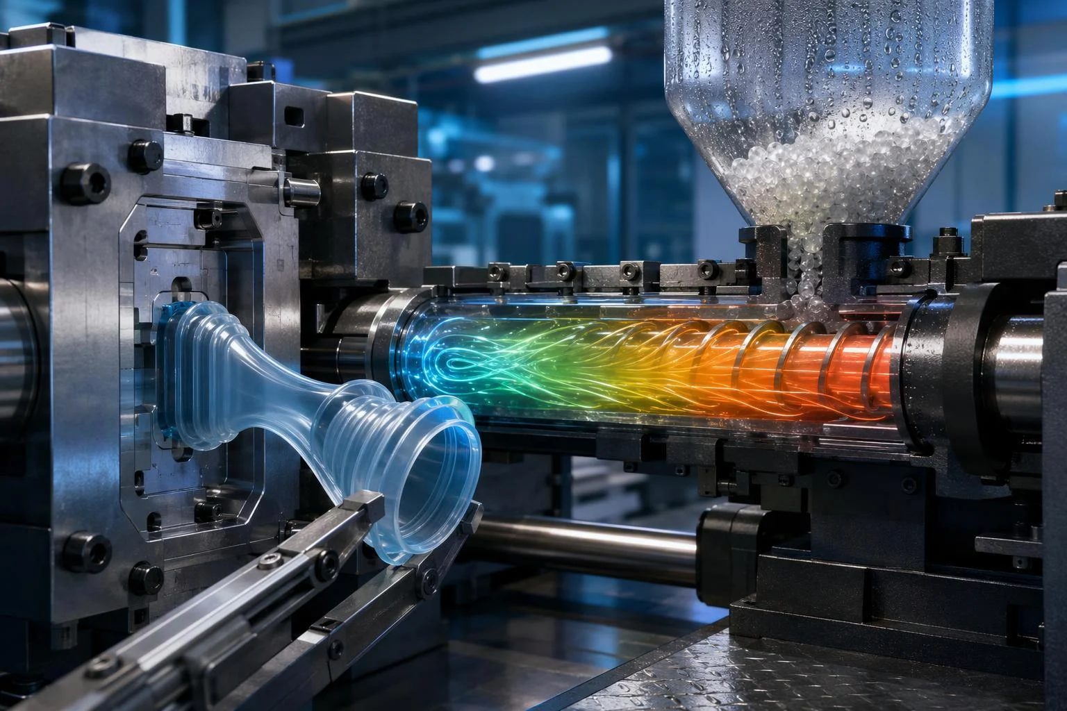
TPU injection molding is not rigid-plastic molding with a softer resin. Thermoplastic polyurethane melts and flows like a thermoplastic, but it is shear-sensitive, it absorbs moisture from the air, and it releases from a tool with an elasticity that changes how the mold must be built. A parameter set copied from an ABS or polypropylene job will usually produce parts — and then produce splay, sink, sticking or a compression set that never reaches the datasheet value.
This guide follows the decisions in the order a project meets them: what the material is and why it behaves as it does, the process stage by stage, the parameters that decide part quality, part and mold design, grade selection, applications, comparisons with other materials and processes, and defect diagnosis. It is written for product developers, design engineers and sourcing teams who need to move from a drawing to a validated part.
The figures below are drawn from published TPU processing recommendations and are starting points, not settings. Grade datasheets, machine condition and tool geometry all shift the window, so every number should be confirmed in a molding trial on the actual machine, tool and grade before it is written into a process sheet. This guide is maintained and refreshed as processing guidance evolves.
What Is TPU Injection Molding and Why It Behaves Differently
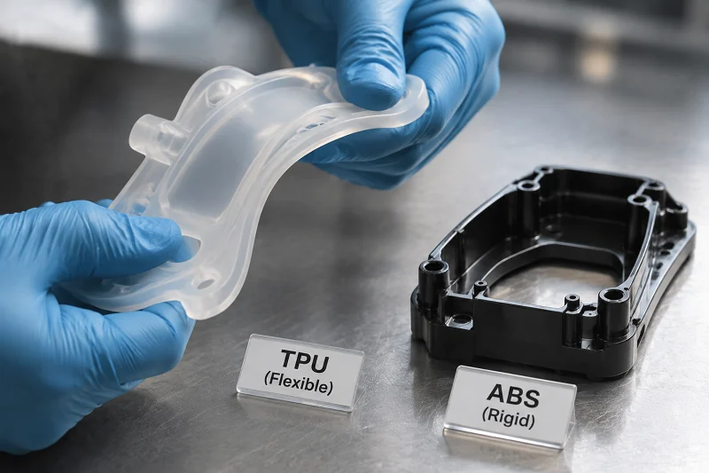
Thermoplastic polyurethane is a block copolymer built from hard and soft segments. The hard segments pack together and act as physical crosslinks; the soft segments give the material its rubber-like recovery. Heat melts the physical crosslinks out, and cooling repacks them. That is the whole reason TPU can be injection molded on standard thermoplastic equipment: nothing in the tool has to cure, and the phase structure re-forms as the part cools.
The same structure explains the material’s range. TPU is available from roughly 60 Shore A to about 74–75 Shore D, and the property set changes continuously across that span — soft grades behave like rubber, hard grades like a tough engineering plastic. For a project this means one material family can replace several, but it does not mean one tooling strategy covers the range. Shrinkage, demolding force, cooling time and the tendency of the melt to shear-degrade all move with hardness, so a hardness change late in a program is a tooling and validation event, not a substitution.
Thermoplastic Versus Thermoset: The Reprocessing Difference
Vulcanized rubber is chemically crosslinked. Once the crosslinks form, the part cannot be re-melted; the network is permanent. TPU’s crosslinks are physical and thermally reversible, so the material re-melts, can be reground, and needs no curing stage in the mold.
The practical consequences are shorter cycles, no crosslink chemistry to control in the tool, and scrap that can be recovered rather than discarded. The trade-off is that a freshly molded TPU part has not yet reached its stated properties. It continues to develop them at room temperature, and the datasheet values are measured on annealed, conditioned specimens. Annealing in a circulating-air oven shortens that equilibration to roughly 15–20 hours and is the only way to reach optimum compression set. Thermoset rubber cannot be re-melted at all, which is why TPU competes wherever rubber’s cycle time and scrap economics are unfavorable — and why TPU’s own annealing step has to be scheduled into production rather than treated as optional.
Why Shear Sensitivity and Moisture Uptake Govern Everything
Two material constraints shape nearly every decision in the rest of this guide.
The first is shear sensitivity. TPU melts are sensitive to shear, and excessive screw speed can reduce the properties of the finished part. This is not a marginal effect: it is why back pressure is kept low, why injection speed is set as low as the gating and wall thickness allow, and why screw speed is limited by a maximum circumferential velocity rather than a fixed rpm. A processor who runs TPU like a fast-cycling commodity resin will get parts that look acceptable and test below specification.
The second is moisture. TPU granulate absorbs atmospheric moisture, and the absorbed water turns to steam in the barrel, producing splay, silver streaks and internal bubbles. The material must be dried to the residual moisture level the grade requires before it goes into the hopper, and it must stay dry there. Drying and material conditioning are covered in the process section; the parameter consequences are covered in the processing section. Neither can be treated as a housekeeping detail.
The TPU Injection Molding Process, Stage by Stage
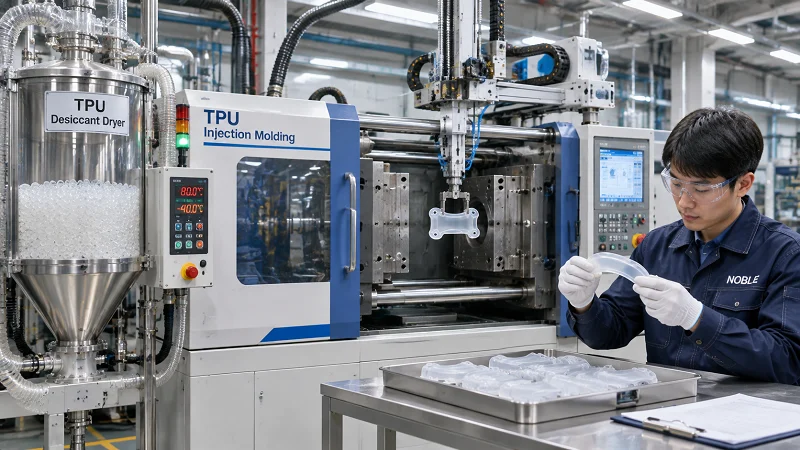
A TPU injection molding project is a chain of stages in which each one constrains the next. The grade chosen in stage 1 sets the drying temperature and the barrel profile; the drying quality sets the achievable surface; the screw and nozzle configuration set how much shear the melt sees; the cooling and demolding decisions set the cycle time and the defect rate. Cost, risk and lead time accumulate along that chain, and the cheapest place to correct a mistake is always earlier than where it is usually found.
Stage 1: Application Requirements and Grade Shortlisting
Start from the part’s duty cycle rather than from a material name. The questions that decide the shortlist are: what abrades or flexes against the part, and how many cycles must it survive; what temperature range it sees in service and for how long; what oils, greases, fuels, cleaning agents or body fluids it contacts; what regulatory class applies; what hardness the function requires; and whether the part must be clear, translucent or color-matched.
Those answers narrow the field to a TPU family — polyether, polyester or polycaprolactone — and then to a hardness. Hardness selection is not cosmetic: it drives the processing temperatures, the cycle time, the shrinkage and the demolding behavior described later in this guide. A part specified at 85 Shore A and later changed to 95 Shore A is a different molding problem, not a different color.
Stage 2: Drying and Material Conditioning
TPU is hygroscopic, and drying is the stage most often under-specified. Published recommendations put the residual moisture target at below about 0.02% in one set of processing guidance and at ≤0.05% in another, with the difference reflecting grade and source rather than a contradiction to be resolved here. Drying is typically carried out at roughly 110 °C in circulating or dry air, with dry-air dryers reaching the target faster; one source gives a range of 80–110 °C depending on hardness, with drying times of one to three hours.
The grade datasheet governs. What the process must guarantee is that the target is actually met: dried hot granules should not be left to cool in open air, they must go into dry, re-sealable containers, and the machine hopper must stay covered. Additives, functional concentrates and colorants must also be pre-dried — undried masterbatch is a frequent and easily overlooked cause of surface defects.
Stage 3: Machine and Screw Setup
TPU runs on standard screw injection molding machines, but not on every screw. The proven configuration is a single-flighted, three-zone screw of normal length, roughly 18–22 D, with a compression ratio around 2:1 that should not exceed 3:1. Short compression-zone screws are unsuitable because they impose high shear stress on the melt. A check ring should be fitted, and the nozzle — free-flow or automatic shut-off — must have smooth channels with no dead spots where melt can lodge and char.
TPU is neither corrosive nor abrasive, so no special screw alloy or armoring is required. What the machine does need is enough drive torque: TPU requires high plasticating energy, and insufficient torque produces fluctuating screw speed and non-uniform melt.
Stage 4: Injection, Holding and Cooling
The cycle itself is covered numerically in the processing parameters section. The sequence is: inject at a speed kept as low as the gating and wall thickness permit; switch to holding pressure, which governs dimensional stability and sink; keep back pressure low because of shear sensitivity; and cool for a time set by wall section, hardness and mold temperature.
Injection pressure and holding pressure sit in the 100–1000 bar range, and back pressure is typically 5–20 bar. The failure modes are directional: too little holding pressure produces sink marks, while excessive injection pressure makes demolding difficult. Cooling is where cycle time is won or lost, and it scales with wall thickness and hardness rather than following a universal figure.
Stage 5: Demolding, Annealing and Post-Treatment
TPU parts reach their optimum physical property level only after time at room temperature. Annealing in a circulating-air oven shortens that to roughly 15–20 hours. Published windows are about 80–90 °C for hardness up to 92 Shore A and 100–110 °C for 93 Shore A and above; another set of recommendations cites 20 hours at 100 °C. Compression set in particular can only be optimized by annealing, which is why the datasheet values assume it.
Parts with low dimensional stability may need support during annealing to avoid deformation. Annealing is a process step with its own handling requirements, not a passive wait.
Stage 6: Inspection and Quality Control
Inspection on a TPU part covers dimensions against shrinkage-adjusted drawings, hardness, appearance — flow lines, splay, flash — bond integrity where the part is overmolded, and functional checks such as flex life and seal performance. Because shrinkage continues after molding, dimensional inspection has to be timed consistently relative to annealing and stabilization.
First-article inspection should be repeated after any change of grade, colorant or regrind ratio. Each of those changes alters shrinkage, flow or color, and a part that passed on the original configuration has not been qualified on the new one.
Processing Parameters That Decide Part Quality
The numbers below are the settings a processor actually adjusts. They are published starting ranges; the grade datasheet and a molding trial on the production tool govern. Where sources differ, the difference usually tracks grade and hardness rather than indicating an error.
Temperature Profiles by Hardness
Barrel and melt temperatures rise with hardness. The published bands are:
| Shore hardness | Barrel (heating zone) temperature | Melt temperature | Nozzle temperature |
| 60A–80A | 170–210 °C | 190–205 °C | 200–210 °C |
| 85A–95A | 190–220 °C | 205–220 °C | 210–225 °C |
| 98A–74D | 210–230 °C | 215–235 °C | 220–240 °C |
Temperature should climb by roughly 10–20 °C from the feed zone to the metering zone, and the nozzle should be set close to the melt temperature. One source notes that some hard grades may need melt temperatures up to about 260 °C; that is a grade-specific requirement, not a contradiction of the bands above, and it should be confirmed against the grade datasheet. Small machines generally need higher settings than large ones. Melt temperature should be measured rather than inferred from controller setpoints, and the controllers adjusted accordingly.
Pressure, Speed and Screw Rotation
Injection pressure and holding pressure both sit in the 100–1000 bar range. Holding pressure influences dimensional stability and demoldability: too low and sink marks appear, too high and demolding becomes difficult. A holding pressure around half the injection pressure is a common starting point for low internal stress. Back pressure provides homogenization but must stay low — 5–20 bar — because the melt is shear-sensitive.
Injection speed should be kept as low as possible, subject to gating, wall thickness and flow distance. Screw speed is limited by a maximum circumferential velocity of about 0.2 m/s, which means the permissible rpm falls as screw diameter rises. Violating these limits has predictable consequences: over-shearing reduces final part properties, excessive injection pressure makes demolding difficult, and insufficient holding pressure leaves sink marks.
Mold Temperature and Cycle Time
Mold temperature typically falls between 15 and 70 °C depending on grade and part, and it has a decisive influence on surface quality, shrinkage and warpage. Modified and glass-fiber grades may need mold temperatures up to about 80 °C to achieve an optimum surface finish, and thick-walled parts can sometimes be cooled further to shorten the cycle.
Cycle time is governed by solidification and demolding behavior, and depends on hardness, wall thickness and mold temperature. There is no universal cycle time to quote. Where warpage is a risk, running the two mold halves at different temperatures is a recognized countermeasure.
Purging, Stoppages and Residence Time
Prolonged dwell overheats the material in the cylinder, and published guidance calls for purging the cylinder before resuming production after stoppages exceeding roughly 10 minutes. The same logic applies to residence time: a shot volume that is very small relative to the cylinder capacity leaves melt sitting in the plasticating unit for a long time, which risks thermal damage. Practical guidance suggests running the cylinder at roughly 30–75% capacity utilization and keeping the metering stroke between about 1D and 3D, with 4D as a maximum.
Long residence time and overheating show up downstream as splay, discoloration and black specks, so the purge discipline is a defect-prevention measure as much as a housekeeping one.
Designing TPU Parts for Injection Molding

Design rules for TPU follow from how an elastic, shrinkage-prone, shear-sensitive melt fills a cavity and releases from it. They are not a generic wall-thickness checklist with a different material name at the top.
Wall Thickness, Transitions and Shrinkage Allowance
TPU tolerates some wall variation better than rigid plastics because its elasticity absorbs minor dimensional differences. Sudden section changes are still a problem: they cause sink, voids and flow marks, and they create the abrupt rigidity changes that produce buckling lines. Gradual transitions remain the rule.
Shrinkage is the harder number to pin down. A shrinkage of approximately 1% is a reasonable rough guide for mold design, but total shrinkage varies with wall thickness and hardness, and published curves span roughly 0.5–2.5%. Total shrinkage is the sum of molding shrinkage and post-shrinkage, and post-shrinkage occurs not only during annealing but during longer-term storage — which is why shrinkage is difficult to predict with great accuracy. Post-molding shrinkage is greater for soft grades and thin walls than for hard grades and thick walls. Glass-fiber-reinforced grades shrink far less: about 0.05–0.20% in the flow direction and 0.1–0.5% transverse to flow.
Draft, Radii and Undercuts
TPU’s flexibility allows quite large undercuts, and short-term overstretching below about 5% does not produce permanent deformation. That can eliminate side actions and simplify the tool considerably. It does not excuse inadequate draft: published guidance calls for drafts of at least about 5°, particularly for soft grades, because insufficient draft still causes scoring and sticking. Generous radii at corners improve flow and reduce frozen-in stress.
Ribs, Bosses and Wall-to-Rib Ratios
Ribs stiffen a part, but they also create the section change that produces sink on the opposite, visible face. Proportion ribs so the rib section does not feed a thick mass into a thin wall, and use gradual transitions where the rib meets the base. Abrupt rigidity changes at ribs are a known cause of buckling lines — visible lines or shimmering areas that appear depending on the angle of light. The correct ratio depends on wall thickness, hardness and appearance requirements, so it is better derived from those than copied as a single universal figure.
Gate Location and Its Effect on Properties
Gate position sets molecular orientation and therefore mechanical anisotropy: a part gated at one end is not the same part, mechanically, as one gated at the center. Gates should sit in the region of maximum wall thickness, and they should be large enough to carry holding pressure and avoid sink marks.
Recommended gate types include sprue, diaphragm, ring and film gates, with pin gates acceptable for small parts. Submarine gates are not recommended because of the material’s high elasticity and the risk of shear degradation, and the softer grades are especially prone to problems with them. Runners should be generously sized to avoid localized shearing and to transfer pressure; a circular runner cross-section gives the best flow characteristics, and multi-cavity tools need a balanced runner system. Where hot runners are used, externally heated systems are preferred.
Ejection, Venting and Surface Finish
Ejectors should be two to three times larger than those used for hard thermoplastics, and they should carry venting channels so that no vacuum forms during demolding. Air must be able to escape the cavity as the melt enters: vent channels roughly 0.02–0.05 mm deep, located at the parting line, inserts and pins, prevent compressed air from causing burn marks.
Mold surface finish runs against intuition. For TPU, a mold surface with a roughness height of roughly 25–35 µm is recommended to facilitate demolding; polished and chrome-plated surfaces are less suitable because they promote sticking, especially with softer grades.
Designing for Overmolding and Multi-Material Bonds
TPU bonds well to some rigid substrates through polarity matching and re-melt at the interface, but compatibility is grade- and substrate-specific and must be qualified by test rather than assumed from a material-family chart. In overmolding, the incoming melt needs enough residual heat to re-melt the substrate surface slightly and form a fusion bond; substrates with a much higher melting point lean more heavily on mechanical interlock.
Polyolefin-based materials are generally incompatible with TPU, and polypropylene in particular requires a modified compound or surface treatment such as flame or plasma treatment. Nylon absorbs moisture, and its moisture content at the time of bonding measurably affects surface energy and bond quality, so conditioning has to be controlled and documented. Polycarbonate bonds well but some adhesive chemistries can induce stress cracking that appears weeks later. Metal inserts rely on mechanical interlock — holes, undercuts, knurled grooves — plus a primer, and they should be clean, grease-free and tempered before molding. A substrate-specific peel test using production resin lots and parameters, followed by accelerated aging, is the only reliable qualification.
Choosing the Right TPU Grade
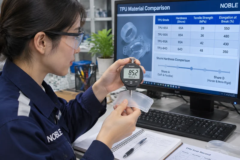
Grade selection is a decision framework, not a product list. The property that most often decides an application — hydrolysis resistance, oil resistance, hardness, clarity, flame performance or regulatory class — should drive the shortlist.
Polyether Versus Polyester Versus Polycaprolactone
The backbone chemistry sets the material’s environmental limits. Polyether grades offer hydrolysis resistance, low-temperature flexibility and resistance to microbial attack, making them suitable where water is a consideration. Polyester grades perform better against oils, greases and abrasion, but flexible polyester TPU can be attacked and decomposed by fungi and bacteria under unfavorable conditions — hot climate, high humidity, soil contact — with discoloration and cracking appearing in loaded areas. Polycaprolactone grades combine the toughness of polyester types with good low-temperature performance and relatively high hydrolysis resistance, and are a common choice for hydraulic and pneumatic seals.
Hardness Selection and What It Changes
Hardness drives processing temperature, cycle time, shrinkage, demoldability and feel. The 60A–75D span lets one material family replace several, and it enables multi-hardness designs through sequential overmolding. The practical consequence is that a hardness change mid-project is a re-validation event: the temperature profile, the shrinkage allowance and the demolding behavior all move with it.
Specialty Grades: Glass-Filled, Flame-Retardant, Transparent, Medical and Food-Contact
Glass reinforcement reduces thermal expansion and shrinkage — even 20% glass content brings the coefficient of thermal expansion close to that of aluminum or steel — and glass-filled grades need higher mold temperatures for an optimum surface. Flame-retardant grades exist for compliance-driven applications, with non-flame-retardant TPU typically meeting HB classification and flame-retarded grades reaching V0 or V2 under UL 94.
Aliphatic grades are light-stable and offer excellent optical clarity, which is why they are used where color stability and transparency matter; aromatic grades can yellow under UV. Medical grades are supported by biocompatibility standards such as ISO 10993-1 and are compatible with sterilization by ethylene oxide, gamma irradiation, dry heat, E-beam and hydrogen peroxide. Food-contact grades are produced under GMP. Specialty grades often narrow the processing window, so the datasheet matters more, not less.
Additives, Colorants and Regrind
Colorant compatibility is a common failure point. Color masterbatches based on TPU are the simplest and most reliable route; SAN-based colorants are suitable to a limited extent; polyolefin- and PVC-based colorants are not suitable. Metering quantities typically run 1.0–4.0% depending on wall thickness and color density. Color pastes, liquid colors and pigments are used at roughly 0.2–1.0%. All colorants and functional additives must be pre-dried.
Regrind is usable within limits. Clean, sorted scrap can be recycled after appropriate treatment and drying, at proportions commonly cited up to 30%, with the regrind matching the virgin material in type and Shore hardness and free from contamination. Regrind should ideally be diced, dried and re-used without intermediate storage; contaminated or degraded material is not suitable, and multiple recycling cycles reduce quality. Particular specified quality requirements may exclude regrind entirely, and optical and medical applications commonly limit or prohibit it.
Where TPU Injection Molding Is Used
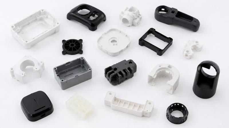
TPU injection molding earns its place in an industry when a part needs abrasion resistance, flex fatigue life, elasticity without plasticizers, or a soft-touch surface bonded to a rigid substrate. The subsections below tie each application area to the property that justifies it.
Automotive and Transportation
Seals, gaskets, boots, bushings, interior soft-touch elements, cable sheathing components and under-hood parts all draw on TPU’s abrasion resistance, oil and grease resistance, and flexibility over a wide temperature range. The limiting factor is the temperature ceiling: continuous use is generally cited at 80–100 °C for polyether grades and 100–120 °C for polyester grades, so under-hood parts must stay within that range. Interior soft-touch components frequently use TPU overmolded onto a rigid substrate.
Medical Devices and Healthcare
Catheters and catheter components, wound-care elements, fluid-management parts, tubing connectors and device housings use medical-grade TPU for its combination of flexibility, transparency, chemical resistance and sterilizability — without plasticizers. Catheter applications span urology, intravenous, gastric, balloon and cardiovascular types. Wound care uses TPU in dressings, drug delivery patches, ostomy bag liners, surgical drapes and mattress protection, where clarity, resistance to kinking and hydrolysis resistance matter.
Consumer Products and Electronics
Protective cases, bumpers, wearable bands, grips and soft-touch housings are the core consumer applications. TPU-over-polycarbonate and TPU-over-ABS overmolding are common for device protection, drawing on the favorable polarity match with those substrates. Watch bands and wearable straps also rely on skin compatibility.
Footwear and Sports
Soles, midsoles, cleats, shin guards and performance components use TPU for abrasion resistance and flex fatigue performance. Footwear is also where aluminum tooling is often used: aluminum molds are cost-effective and well suited to the shorter runs typical of the sector.
Industrial, Robotics and Automation
Wheels, rollers, belts, grippers, bellows, diaphragms and vibration mounts depend on abrasion resistance, tear strength and flex fatigue life. These parts often combine high cyclic loads with exposure to oils and greases, which is where the polyester grades’ resistance profile becomes relevant.
TPU Vs Other Materials and Processes
Comparisons are only useful on the dimensions that decide a project: mechanical performance, temperature ceiling, chemical resistance, processing difficulty, tooling and unit cost. Each alternative below wins somewhere, and the point of the comparison is to identify where.
TPU Vs TPE Compounds (TPS and TPV)
TPU is a reactor-made thermoplastic elastomer: its properties are built into one polymer. TPS and TPV are compounds, made by melt-blending a rubber phase with a thermoplastic. TPU is characterized by high mechanical strength and very good abrasion resistance, and it is generally significantly harder than typical TPS products, so the two rarely compete directly. TPS and TPV win on softness, feel and lower processing demands; TPU wins on strength and wear.
TPU Vs Silicone
TPU offers better abrasion resistance, higher tensile strength and lower cost. Silicone offers a far wider temperature range — roughly −60 to 200 °C against about −40 to 120 °C for TPU — and holds the position in implantable and extreme-temperature applications. Choose TPU when mechanical performance and cost matter more than extreme temperature or implantable biocompatibility.
TPU Vs Thermoset Rubber
TPU wins on cycle time, scrap recovery, design freedom and bondability: no vulcanization stage, regrind potential, and the ability to mold complex geometries and bond to substrates. Thermoset rubber retains superior compression set at high temperature and an established position in dynamic sealing. TPU’s compression set improves with annealing but remains a design consideration rather than a solved problem.
TPU Vs TPEE, PVC and Polypropylene
Against TPEE, TPU generally offers better flex fatigue and abrasion resistance, while TPEE offers advantages in heat and hydrolysis performance. Against plasticized PVC, TPU avoids the regulatory and migration concerns associated with plasticizer, and offers higher mechanical strength. Against polypropylene, TPU offers elasticity and wear resistance, while PP wins on cost and chemical inertness — and, as noted in the design section, PP is one of the hardest substrates to bond TPU to.
TPU Injection Molding Vs Extrusion, Blow Molding and 3D Printing
TPU processes on standard thermoplastic equipment across several methods, and the choice follows part geometry and volume. Injection molding suits complex, tight-tolerance, high-volume parts. Extrusion covers continuous profiles, tubing, cable sheathing and film. Blow molding covers hollow bodies. Additive methods suit prototypes, low volumes and lattice geometries. At very low volumes, machining a part from TPU stock can be the better route — though TPU’s heat generation during machining requires cooling and appropriate tool geometry.
Defect Prevention and Troubleshooting
Most TPU defects trace back to moisture, shear, venting or gate design. Organizing diagnosis by symptom, and knowing which parameter direction typically resolves each, shortens the loop from defect to fix.
Moisture-Related Defects: Splay, Silver Streaks and Bubbles
Splay marks appear as whitish, rough patches; extensive silver streaks as elongated penicillate streaks; large bubbles as air-filled hollows in the wall. All three can result from moisture, though overheating and excessive residence time can produce similar whitish patches. The remedies are to verify dryer performance and the drying process itself, check melt temperature and residence time, reduce screw speed, and confirm that the hopper has stayed covered. Small bubbles can also come from air intake during metering, in which case back pressure within permitted limits and a shorter screw retraction help.
Flow and Fill Defects: Short Shots, Jetting and Flow Lines
Short molding appears at the end of the flow path or at thin-walled locations. Jetting shows as an S-shaped mark near the sprue or gate, caused by an unsuitable gate or throat that produces no frontal flow. Flow lines appear at ribs and section changes. The corrective direction is injection speed staging — slow to fast — gate resizing and repositioning with a deflector surface, and gradual wall transitions. Raising melt and mold temperatures and increasing wall thickness or shortening flow paths also help where the melt is simply too viscous for the geometry.
Thermal Defects: Burn Marks, Black Spots and Degradation
Burn marks come from compressed air in the cavity, so the first response is to optimize venting, particularly near flow lines and at the end of the flow path, and to check vent channels. Black spots and periodic discoloration come from dead spots at sealing faces, cross-section changes or bends in the hot runner, where material lodges and chars; eliminating dead spots and checking sealing faces is the fix. Discoloration from overheating and long residence time calls for lower melt temperature, shorter residence time and purging after stoppages.
Dimensional and Demolding Defects: Sink, Warpage, Flash and Sticking
Sink marks result from insufficient holding pressure or a wall-to-rib mismatch; the remedies are to increase holding pressure and holding pressure time, enlarge the nozzle aperture and sprue cross-section, and adapt the wall-to-rib ratio. Warpage is countered by balancing mold temperature and cooling uniformity, and by evening out speed differences between flow fronts where multiple gates are used. Flash comes from excessive cavity pressure or insufficient clamping force, and is resolved by switching to holding pressure earlier, lowering holding pressure and increasing clamping force. Sticking and scoring trace to inadequate draft, polished mold surfaces, vacuum at ejection or premature ejection — so the fixes are more draft, the recommended surface roughness, optimized venting and longer cooling.
Selecting NOBLE to Support Your TPU Injection Molding Project
NOBLE is a China-based contract manufacturer that supports TPU injection molding programs from concept through production. NOBLE is a Sino-British joint venture, awarded by the government as a “National High-Tech Enterprise”, with over 10 years of experience providing one-stop custom manufacturing from prototyping to production. The company’s stated mission is to turn concepts into reality through on-demand manufacturing that meets strict tolerance and quality standards.
The service model covers the full chain rather than production alone: design support, prototyping, tooling, molding, inspection and assembly. NOBLE holds ISO 9001:2015 and ISO 13485:2016 certification, and its engineering and quality capabilities are intended to help customers move efficiently from prototype to volume production. Quoting is fast — a professional quote can be offered within 24 hours of an RFQ with the necessary information — and rapid lead times are part of the stated offering.
If you have a TPU part to make, the next step is to submit an RFQ with the part information described in the FAQ below; NOBLE will respond with a quote.
How NOBLE Supports Each Stage of a TPU Program
The stages described earlier in this guide map onto NOBLE’s stated service offering as follows. In the requirements and design stage, NOBLE provides design support, which is where DFM input on wall transitions, gate position and shrinkage allowance is most valuable. For prototyping, NOBLE’s rapid prototyping capability lets a design be verified before tooling is committed. Tooling and molding follow in-house, and inspection draws on a full set of inspection equipment and an overall quality control system. Assembly completes the chain, so a program does not have to be split across multiple suppliers.
Each of these capabilities is part of NOBLE’s stated one-stop offering. The specific scope for a given part — which stages are included, and to what specification — is confirmed in the quote.
Quality Systems and Medical-Device Relevance
ISO 9001:2015 certifies a documented quality management system; ISO 13485:2016 certifies a quality management system aligned to medical-device manufacturing. For a buyer, these mean that processes, records and corrective actions follow an auditable framework rather than depending on individual practice.
Certification supports a quality process, but it does not by itself certify a specific part. Part-level validation, and any regulatory submission the device requires, remain project-specific and are agreed as part of the program.
FAQs About TPU Injection Molding
What moisture content should TPU be dried to before molding?
Published targets range from below about 0.02% to below 0.05% residual moisture, depending on source and grade. Drying is typically done at roughly 110 °C in dry or circulating air, with some guidance giving 80–110 °C depending on hardness and drying times of one to three hours. The grade datasheet governs. See the drying stage above.
Can TPU be reground and re-molded?
Yes, within limits. Regrind should be diced, dried and re-used promptly, at proportions commonly cited up to 30% and matching the virgin grade in type and hardness. Contaminated or degraded material is unsuitable, repeated recycling reduces quality, and specified requirements may exclude regrind entirely.
Why do TPU parts sometimes fail dimensionally after molding?
Because total shrinkage is the sum of molding shrinkage and post-shrinkage, and post-shrinkage continues during annealing and longer-term storage. Wall thickness, gate design and processing conditions all influence it, and post-molding shrinkage is greater for soft grades and thin walls. Shrinkage should be validated on the actual tool rather than taken from a single nominal value.
Is TPU suitable for medical device components?
Medical-grade TPU grades exist, are supported by biocompatibility standards such as ISO 10993-1, and are compatible with sterilization by ethylene oxide, gamma irradiation, dry heat, E-beam and hydrogen peroxide. Suitability is determined by the specific grade, the application and the regulatory pathway — not by the material family alone.
How does TPU compare with silicone for a flexible part?
TPU offers better abrasion resistance, higher tensile strength and lower cost, with a service range of roughly −40 to 120 °C. Silicone offers a far wider range, roughly −60 to 200 °C, and holds the implantable and extreme-temperature applications. The choice follows which of those differences the part actually needs.
What causes black specks or burn marks in TPU moldings?
Dead spots in the hot runner, nozzle or sealing faces where material lodges and chars; overheating and long residence time; and inadequate venting that lets compressed air burn the part. The corrective direction is to eliminate dead spots, verify venting, purge after stoppages, and check melt temperature and screw speed.
Can TPU be overmolded onto rigid plastics?
Yes, but bonding is substrate- and grade-specific. ABS and polycarbonate generally bond well, nylon’s moisture content affects bond quality, and polyolefins such as polypropylene generally require modified compounds or surface treatment. Qualification should be by peel test with production resin lots and parameters, followed by accelerated aging.
How do I start a TPU injection molding project with NOBLE?
Share the part drawing or 3D model, the application requirements (duty cycle, temperature, chemical exposure, regulatory class), the target hardness and volume, and any regulatory constraints, then submit an RFQ. NOBLE can offer a professional quote within 24 hours of receiving the necessary information.