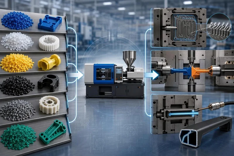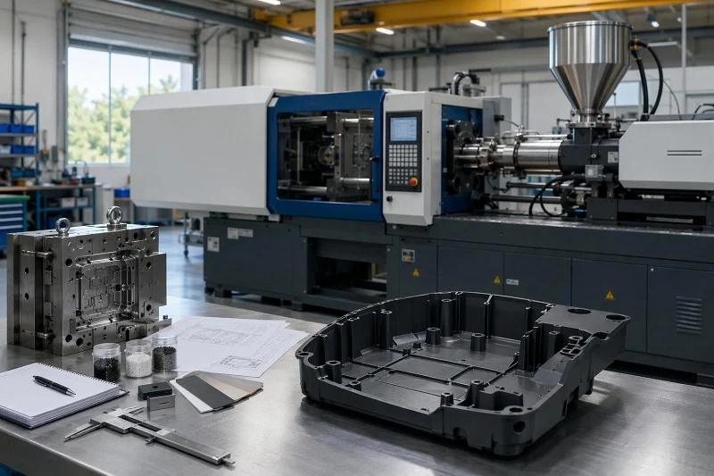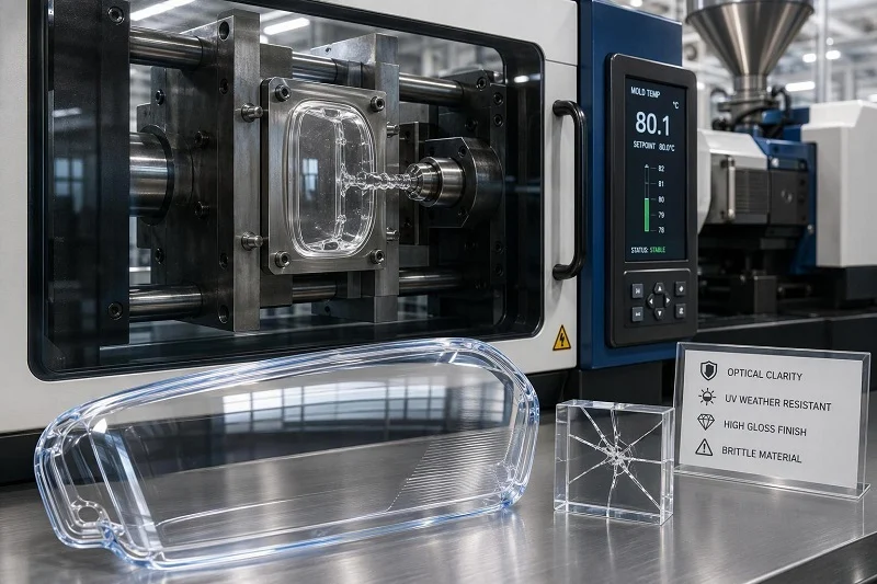
Acrylic injection molding is the process of melting polymethyl methacrylate (PMMA) pellets and forcing them under pressure into a mold cavity to produce transparent, semi-transparent or opaque parts. On paper it resembles any other injection molding cycle: melt the resin, fill the cavity, pack, cool, eject. In practice, acrylic behaves differently enough from commodity resins that treating it as a drop-in substitute on a standard line is one of the most common and most expensive mistakes in a clear-part program.
The same properties that make acrylic the material of choice for lenses, light guides and display windows — about 92% light transmission at 3 mm, the highest surface hardness of the common thermoplastics, and weathering performance that holds optical quality for a decade outdoors — come bundled with a narrow processing window, notch sensitivity and a strong tendency to stress-crack. A part that looks perfect at the inspection bench can crack during assembly or after a single wipe with the wrong cleaner.
This guide follows the whole arc of an acrylic injection molding program: how acrylic behaves in a press, the cycle stage by stage, grade selection, part and tool design, defect prevention, application mapping, and how molding compares with polycarbonate, thermoforming, CNC machining and 3D printing. It closes with how NOBLE supports acrylic injection molding projects from prototype through volume production.
What Is Acrylic Injection Molding and How Does It Behave in a Press?
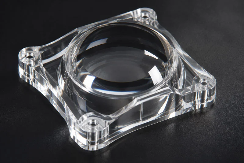
Acrylic injection molding is the process of melting acrylic resin pellets and injecting them under pressure into a mold cavity to produce transparent, semi-transparent, or opaque plastic parts with optical clarity, surface hardness, and weathering resistance that few other thermoplastics can match. The definition is simple; the consequences are not. Acrylic is an amorphous, stiff-flowing, hygroscopic resin that is also brittle, and each of those traits changes how the machine is set up, how the tool is built, and how the part must be handled after ejection.
Acrylic Chemistry and Why It Is Moldable
Acrylic is an amorphous thermoplastic, meaning its molecular chains are arranged without crystalline order. It therefore has no sharp melting point. Instead it softens across a glass transition region — published values cluster around 100–120 °C depending on grade and test method, with one molding-compound data set listing glass transition temperatures from 108 °C to 121 °C across grades. Above that region the chains gain enough mobility to flow under pressure; below it they freeze in place, which is exactly what allows a melt to be injected into a cavity and then held to shape by cooling.
Molding compounds are standardized to the ASTM D788 and DIN 7745/ISO 8257 families, but standardization covers the specification framework, not a single recipe. Molecular weight and comonomer content vary by grade, and those variables move flow, heat deflection and toughness. A high-molecular-weight grade resists stress cracking better but flows with more difficulty; a high-flow grade fills long thin sections but gives up some mechanical performance.
How Acrylic Injection Molding Differs from Molding ABS or Polypropylene
The practical differences show up at every stage of setup:
- Stiffer flow. Acrylic’s melt viscosity is higher than that of ABS or PP, so it needs larger gates, shorter flow paths and generous venting. Processing guidance for acrylic compounds calls for gates “as large as possible” and vents roughly 0.05–0.07 mm deep.
- Mandatory drying. Acrylic is hygroscopic. ABS and PP tolerate far more moisture; acrylic does not, and undried resin produces silver streaks, splay and internal bubbles that are immediately visible in a clear part.
- Hotter molds. Surface gloss and optical quality depend on mold temperatures in the 60–90 °C range, well above what many commodity resins require.
- Stress sensitivity. Over-packing and uneven cooling lock residual stress into the part. In a ductile resin that stress may merely distort dimensions; in acrylic it becomes the seed of a crack.
- Brittle failure. Acrylic does not yield gracefully. A stress concentration at a sharp corner, a gate mark or a scratch becomes a propagating crack rather than a local deformation.
The Material Traits That Shape the Molding Process
Published property data explain most of the processing rules. The figures below are typical values from acrylic sheet and molding-compound data sheets; they vary by grade and should be confirmed against the specific compound’s data sheet.
| Property | Typical value | What it forces the molder to do |
| Density | 1.18–1.19 g/cm³ | Shot-weight calculations and clamp-force estimates follow from it; acrylic is heavier than PP or PS per unit volume |
| Tensile modulus | roughly 3,200–3,300 MPa | Stiff parts resist deflection but transmit stress to corners and inserts; radii matter |
| Notched impact (Charpy) | roughly 1.6–2 kJ/m² | Ejection, handling and assembly must be gentle; impact-modified grades exist for a reason |
| Light transmission | about 92% at 3 mm | Any moisture, contamination or flow mark is visible; process discipline becomes a cosmetic requirement |
| Molding shrinkage | roughly 0.2–0.8% depending on grade and direction | Low and predictable, but the window still has to be validated per grade before steel is cut |
| Continuous service temperature | about 70 °C | Parts near heat sources need high-heat grades, not standard acrylic |
Each row translates into a decision. The low shrinkage makes acrylic attractive for tight-tolerance optical parts, but only if the tool is cut for the right grade. The high modulus and low impact toughness together mean that a design that would be merely inefficient in ABS can be a field failure in acrylic.
The Acrylic Injection Molding Cycle from Pellet to Finished Part
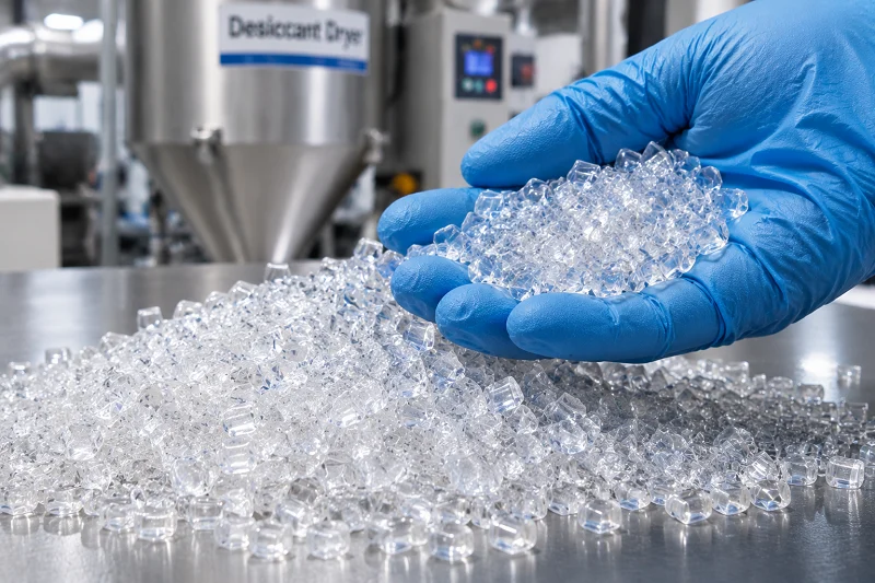
The acrylic injection molding cycle can be read as seven controllable stages. Each has its own parameters, its own failure modes and its own quality check, and a defect that appears at inspection usually originated several stages earlier.
Step 1: Drying the Resin
Drying is not optional. Acrylic absorbs atmospheric moisture, and residual moisture turns to steam in the barrel, producing silver streaks, splay, bubbles and general haze in the finished part. Published drying envelopes differ in detail but agree in direction: one acrylic compound processing guide specifies desiccant drying for 4 hours at 82 °C (or hot-air drying at 77 °C) with moisture below 0.02%; other published guidance gives 80 °C for 2 hours to below 0.1%, or 80–90 °C for 3–4 hours to roughly 0.04–0.05%. The spread reflects differences in compound, pellet form and dryer type rather than disagreement about the principle.
What matters operationally is verification. A timer tells you how long the resin sat in the hopper; it does not tell you the moisture content. Check with a moisture analyzer before the run, keep exposure to ambient air after drying to a minimum, and treat regrind exactly like virgin material — it must be dried again.
Step 2: Melt Preparation in the Barrel
A general-purpose, chrome-plated screw with a standard check ring is the usual recommendation, with a compression ratio of roughly 1.8–3.2:1 and an L/D ratio of at least 20:1. Back pressure is kept low, in the region of 100–200 psi in one published guide, and shot size is typically held to 30–40% of barrel capacity to limit residence time.
Melt temperature is where published sources diverge most visibly. One acrylic processing guide gives a melt range of 205–230 °C with rear, center, front and nozzle zones stepping up accordingly; another gives 240–260 °C; a third places the window at 220–250 °C. These are not interchangeable, and the correct figure depends on the specific grade. The reliable practice is to measure actual melt temperature with a probe in the purged stream rather than trusting controller setpoints, and to validate the window for the compound in the press. Above roughly 260 °C, degradation becomes rapid and produces bubbles, discoloration and irreversible loss of optical quality.
Step 3: Injection
Fill-phase control is about speed and direction. Injection speed should be slow to moderate — fast fill promotes jetting, gate blush and flow marks, all of which are conspicuous on a clear part. Published injection pressures for acrylic compounds sit in the range of 10,000–30,000 psi. On long, thin-walled or optically critical parts, flow simulation is worth the cost: it shows where the melt front will meet itself, where it will cool too early, and whether the gate can carry the part.
Fill speed and gate design together decide whether weld lines and flow marks will be visible. Neither can compensate for the other.
Step 4: Packing and Hold
Hold pressure is the stage where residual stress is either managed or locked in. A graduated hold profile can control sink and voids without over-packing the region around the gate. Over-packing is a leading cause of acrylic parts that pass dimensional and cosmetic inspection and then crack during assembly or solvent cleaning — the stress is invisible until something triggers it.
Published hold pressures for acrylic sit around 500–700 bar in one parameter set, but the profile matters more than the peak number. Hold time depends on part design and should continue until the gate freezes.
Step 5: Cooling
Mold temperature control is central to optical quality. Published mold temperatures for acrylic cluster in the 60–90 °C range, circulated with water or oil. Higher mold temperatures generally improve surface gloss and reduce residual stress, at the cost of cycle time. Uniform cooling — balanced channels on both halves of the tool, conformal layouts where geometry is complex — is the defense against warping and optical distortion on flat panels. As a reference point for the trade-off, one published parameter set cites a cycle time of roughly 25–35 seconds for a 2 mm wall.
Step 6: Ejection
Ejection is a stress event, and in a notch-sensitive material it deserves design attention rather than a default ejector layout. Adequate draft, polished draw surfaces for deep pockets, balanced ejector placement and controlled ejection force all reduce the chance of drag marks, white stress marks and cracked edges. On a clear part, ejector marks and drag marks are cosmetic defects that cannot be hidden or painted over.
Step 7: Annealing
Annealing is the post-molding stress-relief step that separates a part which survives assembly from one which does not. Published guidance for acrylic suggests around 80–90 °C for roughly two hours. The purpose is to relax residual stress built up during filling, packing and cooling, raising the threshold at which the part will craze or crack in service.
Annealing matters most where the part will meet solvents: cleaning agents, hand sanitizers, perfumes, adhesives and potting compounds. A stressed acrylic part exposed to alcohol can craze months after assembly, and the failure is often attributed to the resin when the real cause is the stress left in it.
Selecting the Right Acrylic Grade for Injection Molding
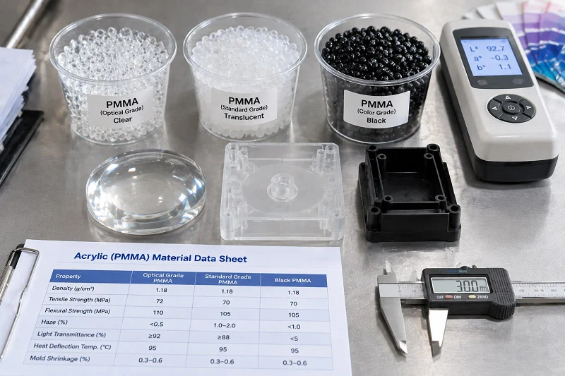
“Acrylic” is a family, not a single specification. Grade choice constrains the tool design, the processing window and the validation plan, and a parameter set validated for one grade should not be carried over to another without revalidation.
Optical Grades
Optical grades are crystal-clear compounds formulated for high transmission over long light paths — light guides, lenses and display components. Their flow properties are tuned per processing method, which means the same nominal clarity can come in grades with quite different viscosities. A grade optimized for a short flow path in a small lens will not necessarily fill a long, thin light guide, and a high-flow grade chosen to fill that light guide may give up some mechanical performance. Match the grade to the part’s geometry and the tool’s flow length, not just to the word “optical.”
Impact-Modified and High-Heat Grades
Impact-modified acrylics use rubber-phase modification to raise toughness, trading some clarity and surface hardness for resistance to impact. Published data for impact-modified molding compounds show light transmission in the high 80s to low 90s percent range, notched impact values several times those of standard acrylic, and somewhat lower heat deflection.
High-heat grades address the other limit. Standard acrylic has a continuous service temperature around 70 °C, which is adequate for most lighting and display work but not for thermally stressed positions. Copolymer grades based on MMA with comonomer constituents raise heat deflection while retaining clarity, and polymethyl methacrylimide (PMMI) grades go further for high-temperature applications such as headlamp lenses and built-in furniture lighting. Each step up in heat performance changes shrinkage, flow and the processing window.
How Grade Choice Constrains the Tool
Grade selection feeds directly into tooling decisions:
- Flow length and gate count. A stiffer grade may need an additional gate or a thicker wall to fill; a high-flow grade may allow a simpler layout.
- Gate size and style. Acrylic generally wants large gates, and fan or film gates spread melt across flat panels to suppress jetting.
- Vent depth. Published venting for acrylic compounds is shallow — around 0.05–0.07 mm deep and several millimeters wide — because the melt is stiff and trapped air has nowhere to go.
- Cooling layout. Higher mold temperatures and uniform cooling drive channel placement and, on complex parts, conformal cooling.
- Polish level. Clear parts typically require cavity surfaces polished to a high SPI finish; the exact grade and finish should be agreed before steel is cut.
The operating rule is straightforward: processing parameters validated for one grade should not be assumed valid for another grade with a different flow and thermal profile. Buyers should confirm not only which grade is on the material certificate but whether the production parameters were actually validated for that grade.
Designing Parts and Tools for Acrylic Injection Molding

Design rules for acrylic follow from its behavior: it is stiff, brittle, notch-sensitive and optically unforgiving. The goal is to keep stress low, keep flow balanced and keep cosmetic surfaces clean.
Wall Thickness, Ribs and Bosses
Uniform wall sections are the first rule. Sudden thickness changes create uneven cooling, differential shrinkage, sink marks, internal stress and optical distortion, and the stress concentrates exactly at the transition line. Gradual transitions — tapering over a distance rather than stepping abruptly — cool more evenly and reduce the risk of cracking both immediately after molding and over service life. A typical acrylic wall may sit around 2–4 mm, but the right value depends on flow length, grade, part size, transparency requirements and structural load.
Ribs should be kept thin relative to the nominal wall — commonly around 40–60% of wall thickness — so they add stiffness without adding local mass that sinks. Bosses should be cored out and connected with thin ribs rather than left as solid columns; a thick solid boss concentrates both shrinkage and stress and is a classic origin of sink marks and cracking. Sharp internal corners should be radiused generously; a common starting point is a radius of at least half the wall thickness at internal corners.
Gate Placement and Weld Lines on Visible Surfaces
Gate location determines where flow lines, weld lines and gate-adjacent stress appear. On optical parts, keeping the gate outside the active optical zone is often a non-negotiable requirement rather than a preference. Fan and film gates spread melt evenly across flat panels and suppress jetting; pin-point gates suit small parts but leave a gate blush that must be cut or hidden.
Weld lines are where two melt fronts meet and fuse. On a clear part they read as visible seams, and they are also mechanically weaker than the surrounding material. Strategies include moving the gate to shift the weld line out of the viewing area, adding overflow wells to control where the fronts meet, raising melt and mold temperature to improve fusion, and hiding the knit line behind an opaque feature or a textured band.
Ejector Marks, Draft and Surface Finish
Clear parts impose surface requirements that opaque parts do not. Draft angles should be generous enough that the part releases without dragging; deep pockets need polished draw surfaces. Ejectors should be placed away from optical zones and sized to spread force over a larger area, because a small ejector pin on a brittle material leaves a white stress mark that cannot be removed.
Cavity finish matters as much as cavity geometry. Published guidance for rigid clear materials points to high polish levels on cavity and core, with the exact SPI grade agreed against the cosmetic standard. Handling after ejection matters too: a polished clear part that is stacked against another part can scratch before it ever reaches the customer.
Managing Residual Stress and Stress Cracking
Residual stress accumulates from three sources: uneven cooling between thick and thin sections, unbalanced filling that packs some regions harder than others, and over-packing at the gate. In acrylic, that stress lowers the threshold at which the part will craze or crack when it meets a solvent.
Acrylic stress-cracks in contact with alcohols, acetone and MEK. Published guidance is explicit that annealing at 80–90 °C for about two hours reduces residual stress and prevents crack initiation in service, and that this is critical for parts exposed to cleaning solvents, hand sanitizer or perfumes. The design and processing levers work together: balanced packing, uniform cooling, generous radii, controlled ejection and annealing. No single one of them compensates for the others.
Metal inserts deserve specific attention. Press-fit stress and thermal expansion mismatch — acrylic expands roughly eight times as much as steel over a given temperature change — build tension around a rigid insert, and any solvent exposure near that point can trigger crazing. Ultrasonic or heat-set inserts, generous boss walls and stress-relief annealing reduce the risk substantially.
Defects in Acrylic Injection Molding and How to Prevent Them

Most acrylic molding defects trace back to a small number of causes: moisture, thermal history, unbalanced flow and residual stress. A diagnostic approach beats guesswork because the same visible symptom can have more than one origin.
Silver Streaks, Splay and Haze
Silver streaks are bright, reflective lines, usually near the gate. They differ from flow marks, which are directional variations in surface texture or color. The dominant cause of silver streaks is moisture in the resin; trapped air and material degradation can produce similar effects. Haze or milkiness across the part points to a cold mold, wet resin or low melt temperature.
The corrective actions are sequential: verify drying with a moisture analyzer rather than a timer, check melt temperature against the grade’s limit, improve venting at end-of-fill areas, and review residence time in the barrel. Purging with a compound designed for acrylic helps clear degraded material. If the defect persists after drying is confirmed, look at thermal history next.
Warping and Optical Distortion
Warpage on flat clear panels comes from uneven cooling and unbalanced filling. Differential shrinkage between a thick section and an adjacent thin one produces a bending moment; on a large flat plate the result can be a visible bow. Optical distortion is the same problem seen through the part rather than measured on it.
The countermeasures are design and process together: uniform walls, balanced gating so all flow paths fill at similar pressure, controlled and symmetric cooling, and inspection for flatness and visual distortion against an agreed standard. On large panels, flow simulation before steel is cut is cheaper than correcting a tool after the fact.
Sink Marks, Voids and Short Shots
Sink marks appear where a thick section cools and shrinks after the gate has frozen, leaving insufficient packing. Voids form inside thick sections for related reasons. Short shots occur when the melt cannot fill the cavity — long flow paths, insufficient gate size, low melt or mold temperature, or inadequate pressure.
The design responses are to core out thick sections, add gates where the flow path is too long, enlarge restrictive gates, and improve venting so trapped air does not block fill. Increasing hold pressure and time helps sink marks only up to the point where over-packing creates a worse problem; the better answer is usually to fix the wall geometry.
Cracking After Molding
This is the most expensive failure mode because it escapes inspection. A part passes dimensional and cosmetic checks, ships, and cracks during assembly, in transit or after the customer wipes it with a cleaner.
The causes are cumulative: over-packing at the gate, stress concentration at a sharp corner or insert, inadequate annealing, and solvent exposure. Validation should therefore include more than a visual check. Assembly trials that reproduce the real joining method, accelerated stress testing, and where relevant exposure to the actual cleaning agent give a far better picture than a flat plaque test. Published guidance on acrylic quality programs also points to cavity-by-cavity part weights over a continuous run, control charts on critical dimensions and periodic cross-polarizer checks for birefringence as evidence that the process is stable.
Where Acrylic Injection Molding Is Used
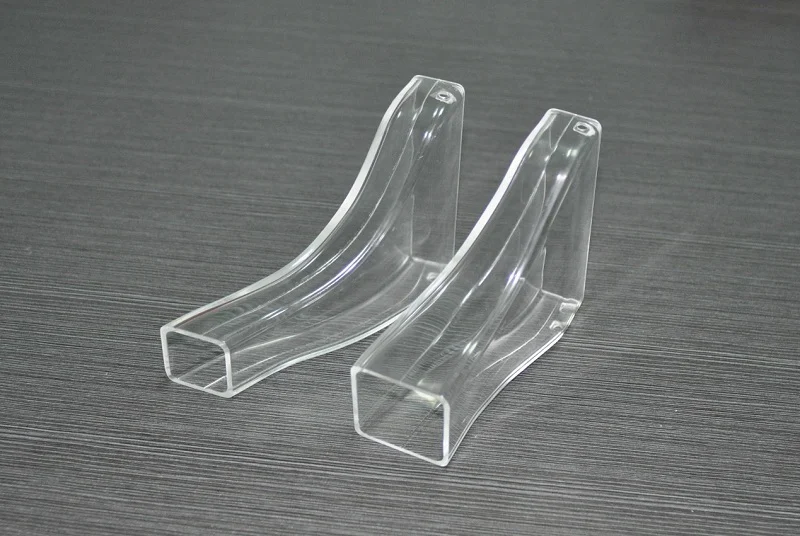
Acrylic injection molding is chosen where clarity, surface hardness and weathering matter more than impact toughness. The applications below map to those properties; the section closes with the cases where acrylic is the wrong answer.
Optical and Lighting Components
Lenses, light guides, LED light pipes and diffusers are the core of the acrylic story. Acrylic’s light transmission of about 92% at 3 mm is the highest of the common transparent thermoplastics, and its Abbe number of roughly 58 means low chromatic dispersion — important in lenses where color fringing would be visible, and in long light guides where polycarbonate would attenuate light and shift color temperature.
Light-diffusing grades extend the family. Published molding-compound ranges include diffusing grades with haze values from around 50% up to 96%, and LED-specific grades with haze below 8% down to below 1%, allowing a designer to tune uniformity of illumination rather than simply maximize transmission.
Automotive Lighting and Trim
Taillight lenses, headlight diffusers and interior lighting components are long-standing acrylic applications. Standard acrylic handles many of these, but thermally stressed positions — headlamp lenses in particular — call for high-heat copolymer or PMMI grades that hold optical values after long-term heat exposure. Decorative interior trim, pillar panels and mirror housings also use molded acrylic where gloss and weather resistance matter.
Medical, Diagnostic and Consumer Applications
Medical diagnostics and device housings use acrylic where clarity and cleanability matter — diagnostic windows, instrument covers and housings that let a user see indicators. Some acrylic grades are approved for food contact, and medical applications require grade-specific documentation rather than a general assumption that “acrylic is fine for medical use.” Beyond that, signage, displays, sanitary ware, transparent trays and consumer product covers all draw on the same combination of clarity, hardness and cost.
Where Acrylic Is the Wrong Choice
The boundaries are worth stating plainly:
- Impact-critical parts. Where a part may be dropped, struck or flexed, polycarbonate is the appropriate material. Standard acrylic’s notched impact is roughly 1.6–2 kJ/m²; polycarbonate’s is an order of magnitude higher.
- Above the continuous service temperature. Standard acrylic is rated around 70 °C continuous. Hot-fill, dishwasher or high-power LED proximity applications need a different grade or a different resin.
- Aggressive solvents. Alcohols, acetone and MEK attack stressed acrylic. Where harsh disinfectants or solvent cleaning are routine, a copolyester or another resin may be the better fit.
- Hot water and steam. These accelerate degradation and are a poor environment for standard acrylic.
Acrylic vs Polycarbonate and Other Transparent Plastics
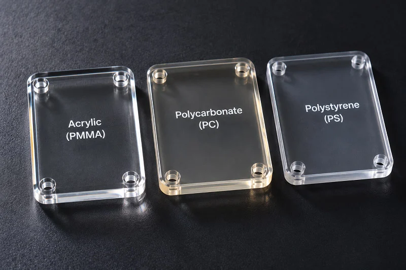
Most acrylic selection decisions come down to a comparison with polycarbonate, with polystyrene and PETG as secondary alternatives. The comparison is only useful if the properties are read at the same conditions and with the same scope.
Acrylic vs Polycarbonate
The central trade-off is optical and surface performance versus impact survival. Acrylic offers light transmission of about 92% at 3 mm against roughly 86–90% for polycarbonate, and its Abbe number of about 58 against roughly 30 means visibly less chromatic dispersion. Its surface hardness is higher — published pencil hardness figures put acrylic at 3H–4H against 2B–HB for polycarbonate — so bare acrylic survives consumer wiping where polycarbonate usually needs a hard coat. Its UV stability is inherent: published outdoor weathering data for acrylic sheet show virtually no yellowing over ten years of natural exposure in Arizona and Florida.
Polycarbonate wins decisively on impact. Published notched Izod figures place polycarbonate at roughly 650–850 J/m at 23 °C against roughly 16–25 J/m for standard acrylic, and its heat deflection temperature is far higher, around 125–135 °C against roughly 85–98 °C for standard acrylic. Polycarbonate is also naturally flame-retardant to a degree that acrylic is not; unmodified acrylic typically rates UL 94 HB.
The decision rule is therefore: choose acrylic where optical clarity, scratch resistance and UV exposure govern, and choose polycarbonate where impact is the governing requirement or where heat or flame performance is mandatory.
Acrylic vs Polystyrene, PETG and Other Clear Resins
Polystyrene is cheaper and processes easily, with transmission in the high 80s to around 90%, but it is brittle without modification and has poor UV stability. PETG sits between acrylic and PC on toughness, with transmission around 90%, but lower heat resistance and softer surfaces. Impact-modified acrylic occupies a middle position: it raises toughness several-fold over standard acrylic while keeping most of the clarity, which makes it a reasonable answer where a standard acrylic part would otherwise be too fragile but polycarbonate’s optical and surface penalties are unacceptable.
A Property Comparison Table for Clear Resins
The table below summarizes typical values. They are grade-dependent and intended for orientation, not for design specifications; confirm against the specific compound’s data sheet.
| Property | Acrylic (standard) | Polycarbonate | Polystyrene | PETG |
| Light transmission (3 mm) | about 92% | roughly 86–90% | roughly 88–90% | roughly 90% |
| Notched impact | roughly 16–25 J/m (Izod) | roughly 650–850 J/m (Izod) | low; brittle unmodified | moderate, between acrylic and PC |
| Heat resistance | HDT roughly 85–98 °C; continuous service about 70 °C | HDT roughly 125–135 °C | low | low |
| UV stability | excellent, inherent | poor unmodified; yellows without stabilization or coating | poor | moderate |
| Scratch resistance | high (3H–4H pencil) | low (2B–HB pencil); usually hard-coated | low | low |
| Relative cost | baseline | roughly 1.35–1.65× acrylic | low | medium |
Acrylic Injection Molding vs Thermoforming, CNC Machining and 3D Printing
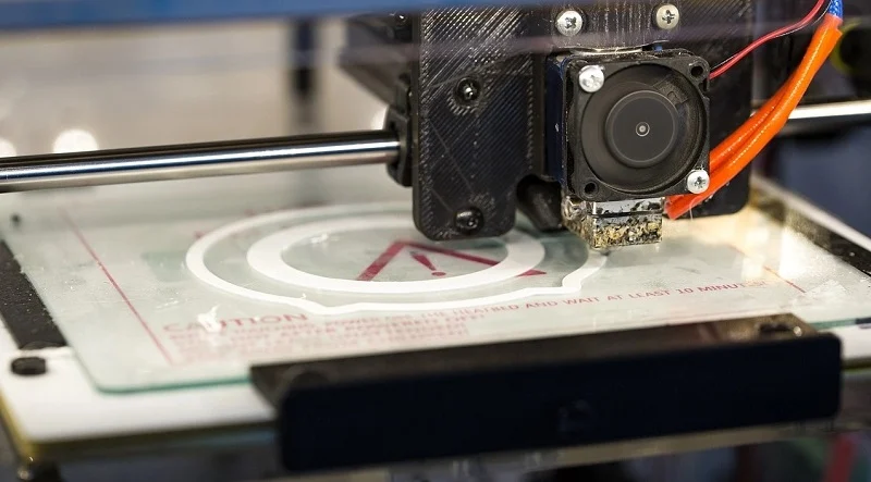
Acrylic parts can be made by several routes. The choice depends on volume, geometry, tolerance and the surface quality the product needs, and the crossover points are economic rather than absolute.
Acrylic Injection Molding vs Thermoforming
Thermoforming starts from acrylic sheet, heats it and forms it over or into a mold. It suits large, flat, cost-driven panels and low volumes, and it avoids the cost of a precision injection tool. Its limits are geometry and repeatability: undercuts, integrated bosses, snap features and tight tolerances are difficult or impossible, and features usually have to be added in secondary operations.
Injection molding wins when three-dimensional geometry, integrated features, tight tolerances and repeatable high volume matter. The tooling investment is higher, but it is amortized across the production run, and each part arrives with the features molded in.
Acrylic Injection Molding vs CNC Machining
Machining acrylic sheet or block requires no tooling and is well suited to prototypes and small batches. It handles simple geometry well and can produce an excellent polished surface. Its constraints are machining time per part, the difficulty of complex internal geometry, and the cost of removing material rather than forming it. For a part that will eventually be molded, machining is often the right way to produce the first functional prototypes and to validate fit before committing to steel.
Acrylic Injection Molding vs 3D Printing
3D printing is valuable for rapid prototypes and one-off clear parts, and it lets a design team hold a physical part within days. Its limitations show up in optical clarity, surface finish and per-part cost at volume: printed clear parts rarely match molded acrylic’s transmission and surface quality, and the cost per part does not fall the way it does with a production tool. The usual pattern is to print for form and fit, then hand off to molding for optical validation and production.
Choosing a Process by Volume, Geometry and Finish
The decision can be reduced to a few questions:
- Is the part large, flat and cost-driven at low volume? Thermoformed sheet is often the practical answer.
- Is it a prototype or a small batch with simple geometry? CNC machining gives good surfaces without tooling.
- Is it a one-off or a form-and-fit check? 3D printing is fastest.
- Does the part need three-dimensional geometry, integrated features, tight tolerances, optical-grade surfaces and repeatable volume? That is the point at which acrylic injection molding becomes the right process.
The crossover moves earlier — toward molding at lower volume — when the part has features that would otherwise require assembly, when cosmetic consistency matters across units, or when the design is stable and unlikely to change. It moves later when the design is still evolving, when annual volume is small, or when the part is large and flat enough that sheet-based processes remain competitive.
Why Choose NOBLE for Your Acrylic Injection Molding Project
NOBLE is a Sino-British joint venture, awarded by the government as a “National High-tech Enterprise,” with more than ten years of experience in custom manufacturing. For an acrylic injection molding project, that experience matters in a specific way: clear parts leave little margin for error, and the difference between a program that runs smoothly and one that does not is usually the depth of engineering and process support behind the tool.
NOBLE’s service capability and processing expertise are directed at helping customers move efficiently from prototype to volume production. The company holds ISO 9001:2015 and ISO 13485:2016 certification, and it provides a full service chain from design through assembly — not production alone.
Prototyping Through Mass Production Under One Roof
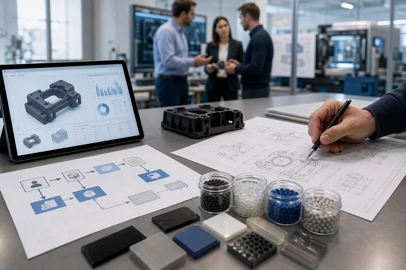
An acrylic program passes through distinct stages, and each one benefits from continuity. Design support covers DFM review, material and grade selection, and tooling concept before steel is cut. Prototyping produces physical parts for fit, function and optical evaluation. Mass production carries the validated process into repeatable volume.
Keeping these stages with one manufacturing partner avoids the handover losses that occur when a design moves between a prototyping shop, a toolmaker and a molder. NOBLE’s in-house capabilities and inspection equipment support that continuity, so the process knowledge gained at the prototype stage carries into production rather than being rebuilt from scratch.
Certification, Quality Control and Full-Chain Service
Acrylic parts are judged on optical quality and on their resistance to stress cracking, and both depend on process control rather than on final inspection alone. NOBLE’s ISO 9001:2015 certification reflects a documented quality management system, and its ISO 13485:2016 certification reflects a quality system aligned to medical device requirements — relevant where acrylic components serve diagnostic or medical device applications.
A full set of inspection equipment and an overall quality control system support dimensional and cosmetic verification, and the service scope runs from design through assembly. For an acrylic project, that means the same partner can address grade selection, tool design, molding, annealing, inspection and assembly — the sequence in which acrylic failures are prevented rather than discovered.
Getting Started with Your Acrylic Injection Molding Project
A successful acrylic injection molding project is built in a sequence, and each step depends on the one before it.
- Define the requirements. Optical performance (transmission, haze, clarity over the light path), mechanical loads, impact exposure, service temperature, cleaning chemistry and cosmetic acceptance criteria should be written down before a grade is discussed.
- Select the grade. Match the family — optical, impact-modified, high-heat, light-diffusing, medical or food-contact — to those requirements, and confirm the specific compound’s data sheet.
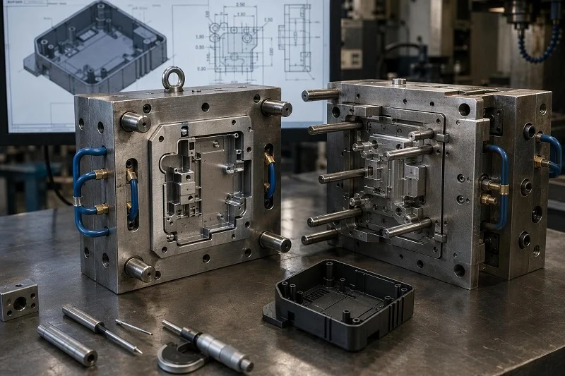
- Design the part and tool around acrylic’s behavior. Uniform walls, generous radii, cored bosses, gate placement outside optical zones, adequate draft, polished draw surfaces and balanced cooling.
- Validate drying and process parameters. Verify moisture with an analyzer, measure actual melt temperature, and establish the window on the press for the specific grade.
- Plan annealing and inspection. Build stress relief into the process for parts exposed to solvents, and define the cosmetic and dimensional acceptance standard before production.
- Validate in the real assembly. Test with the actual joining method and the actual cleaning agent, because that is where latent stress reveals itself.
If you would like to discuss an acrylic injection molding project, NOBLE can review your requirements, advise on grade and tooling, and quote prototyping through production. Submit your drawings, target volumes and performance requirements to start an engineering review.
FAQs About Acrylic Injection Molding
Can Acrylic Actually Be Injection Molded?
Yes. Acrylic is routinely injection molded into lenses, light guides, display windows and countless other clear parts. What makes it different from molding other clear resins is the combination of traits it brings to the press: it is hygroscopic and must be dried, it flows stiffly and needs large gates and short flow paths, it requires mold temperatures in the 60–90 °C range for surface quality, and it is notch-sensitive, so ejection and handling must be gentle.
What Melt and Mold Temperatures Should Acrylic Injection Molding Use?
Published sources differ. Melt ranges in the available guidance include roughly 205–230 °C, 220–250 °C and 240–260 °C; mold temperatures cluster around 60–90 °C. The differences reflect different grades, compounds and test conditions rather than a single correct answer. The right window is grade-specific: start from the compound supplier’s data sheet, measure actual melt temperature with a probe rather than trusting controller setpoints, and validate the window on the press before production.
Why Do Molded Acrylic Parts Crack or Haze After Molding?
The main causes are residual stress, over-packing, solvent exposure, and moisture or thermal degradation. Over-packing at the gate locks stress into the part; uneven cooling does the same at thickness transitions. When the part later meets an alcohol, acetone or MEK — in a cleaner, a hand sanitizer or a perfume — that stress becomes a crack. Haze usually points to moisture or a cold mold. The remedies are process control, generous radii, balanced packing, uniform cooling and annealing at around 80–90 °C for roughly two hours.
Is Acrylic or Polycarbonate Better for My Part?
Choose acrylic when optical clarity, scratch resistance and UV exposure are the governing requirements, and when impact exposure is low and controlled. Choose polycarbonate when the part may be dropped, struck or flexed, or when heat or flame performance is mandatory. Where a standard acrylic part would be too fragile but polycarbonate’s optical and surface penalties are unacceptable, an impact-modified acrylic grade is often the middle path.
At What Volume Does Acrylic Injection Molding Beat Other Processes?
There is no universal break-even number, because the crossover depends on tool cost, part size, cycle time, material cost and how much secondary assembly the molded part eliminates. The logic is tooling amortization: the tool is a fixed cost spread across the run, so higher volume lowers the per-part tooling burden. The crossover moves earlier when the part has integrated features that would otherwise require assembly, when cosmetic consistency matters across units, and when the design is stable. It moves later when the design is still changing or when the part is large and flat enough that thermoforming or machining remains competitive.
Which Acrylic Grade Should I Specify?
The main families are optical grades for high transmission over long light paths, impact-modified grades for toughness, high-heat copolymer and PMMI grades for elevated service temperatures, light-diffusing grades for uniform illumination, and grades documented for medical or food-contact applications. Match the grade to the application’s actual demands — optical path length, impact exposure, service temperature, cleaning chemistry — and validate the processing window in the actual tool rather than assuming parameters from a previous acrylic program will transfer.