Introduction
A part might be spot-on in terms of the measurements on the print, but it might still be useless. The difference between success and failure is often about the surface finish. If you don’t finish it properly, a good component can end up being useless.
Defects can end up costing you in three different ways. Firstly, you spend extra time on secondary operations such as sanding, polishing, and reworking. Secondly, you lose money due to scrap rates when parts can’t be salvaged. Thirdly, a poor surface can hide bigger problems. It creates weak points where cracks start. Parts fail more quickly.
This guide will show you the most common surface defects. You’ll learn what causes them, how to spot them, and, most importantly, how to fix them. The idea is pretty straightforward: less waste and more reliability.
What Are Surface Defects in CNC Milling?
In order to fix a surface defect, it is first necessary to understand what you are looking at. Two important terms are involved here.
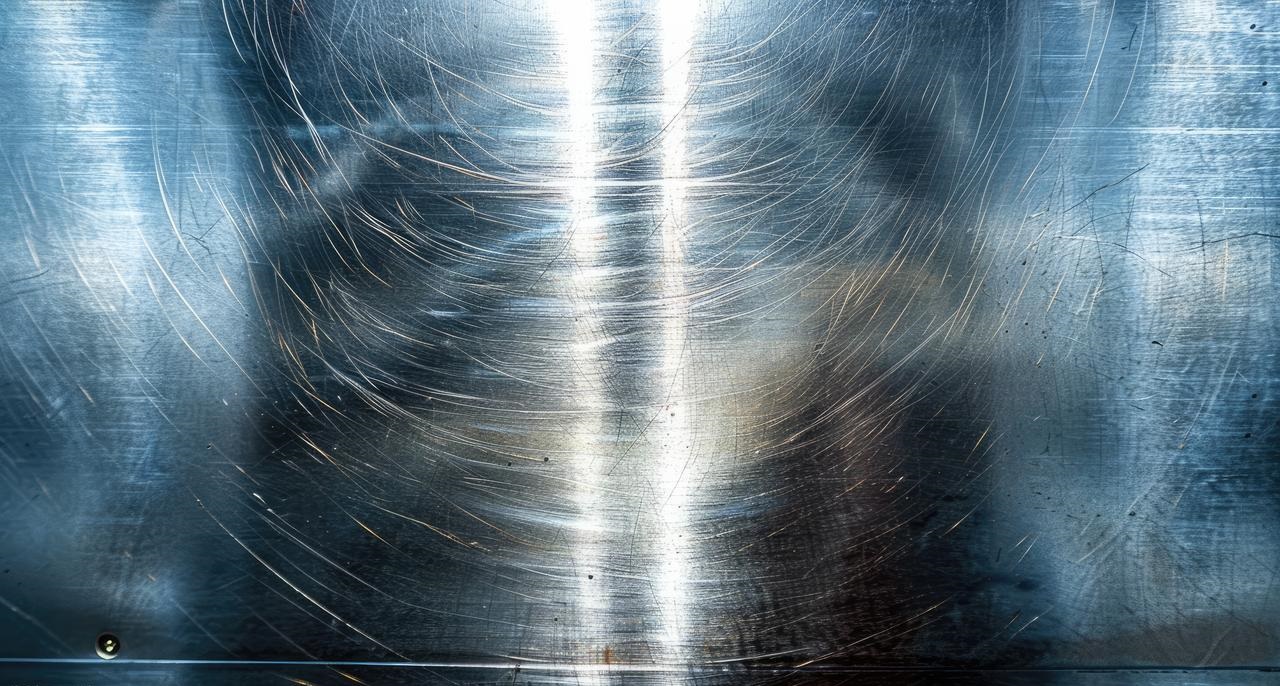
Surface topography is essentially the shape of the surface. There are highs and lows. Texture is what you can see and feel. Surface integrity goes deeper. Here, the important factor is the physical properties, such as changes in hardness, microcracks, and residual stresses. A part may appear smooth, but there could be hidden damage underneath.
Surface defects are essentially just deviations. The surface isn’t quite right for the print. This could be due to the geometry being incorrect, such as a gouge, tear, or ridge. Alternatively, there could be a physical flaw, such as burning, cracking, or debris becoming lodged in the part. Either way, the part is damaged.
How do you identify them? There are two ways to go about it. The first step is to check visually. An experienced machinist will spot any problems straight away. For more precise work, use a profilometer. This tool drags a stylus across the surface and provides numerical data. Ra measures the average roughness. Rz looks at the maximum height of the peaks and valleys. Together, they tell you if the finish meets the required specifications.
The 5 Root Causes of Milling Surface Defects
Here is a framework to help you systematically diagnose surface defects. When a poor finish is observed, check the following five areas in order: tooling, cutting parameters, machine rigidity, material, and the CAM programme. One of these is almost always the cause.
1. Tooling-Related Defects
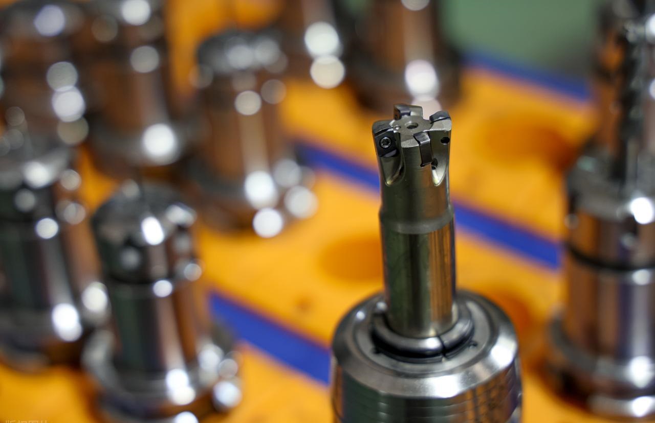
The cutting tool is your first suspect. It touches the part directly.
- Chatter marks look like a washboard pattern on the surface. They are caused by harmonic resonance. This occurs when the tool vibrates against the part instead of cutting cleanly. The most common cause is excessive tool overhang. A good rule of thumb is to keep the length-to-diameter ratio below 4:1. Anything longer than that, and you’re asking for trouble.
- Built-up edge occurs with aluminium and other sticky materials. Small chips weld themselves to the tool tip under heat and pressure. This welded material then tears at the surface instead of cutting it. The result is a rough, torn finish.
- Burr formations show up at part edges. An entrance burr forms where the tool enters. An exit burr forms where the tool leaves. Both are signs of dull tooling or an incorrect lead angle. A sharp tool with the correct geometry cuts the material cleanly. A dull tool pushes the material aside, creating a raised edge.
- Tool wear is gradual but destructive. A worn tool stops cutting and starts rubbing. This generates heat and leaves an inconsistent, burnished finish. Check your tools regularly. When they go, everything goes with them.
2. Process & Parameter Defects
The numbers you enter into the machine control everything.
Consider the speeds and feeds triangle. There are three variables: spindle speed, feed per tooth, and depth of cut. These must be balanced. If you change one, you must adjust the others.
- Thermal damage shows as burn marks on the part. This occurs when a high spindle speed is used with a low feed rate. The tool dwells in one area, causing friction and burning the material. The solution is to increase the feed rate and allow the tool to move.
- Work hardening is a risk with stainless steels and some exotic alloys. If your feed rate is too low, the tool will rub against the material instead of cutting it. This work-hardens a thin layer of material through rubbing. The next pass then has to cut hardened material. Tools wear out faster and finishes deteriorate. The solution is to maintain a sufficient chip load. You must cut, not rub.
3. Machine & Workholding Defects
- Backlash refers to the slop in your machine’s drive screws. When the tool changes direction, this gap closes, leaving a surface defect. This is visible where two tool paths meet, as a small line or step that shouldn’t be there. This is most noticeable on old machines. The solution is proper maintenance or software compensation.
- A tram error occurs when the spindle head is not perfectly square to the table. On face-milled surfaces, a stair-step pattern appears. This is because the tool cuts deeper on one side of its rotation than the other. Check the tram with an indicator. Adjust the head until it is perfectly square.
- Vibration loops start with a loose clamp or a weak fixture. This tiny movement is amplified by the cutting forces. The whole setup starts shaking. The part shows chatter, but it’s not the tool’s fault. Check your clamps first.
4. Material Defects
- Inclusions and porosity: Defects originating from the raw material (castings). Sometimes, the problem isn’t how you cut. It’s what you started with.
- Inclusions and porosity come from the raw stock itself. Castings are usually the culprit. You machine through a clean surface and hit a void or a hard spot. The tool skips, the finish breaks, and the part is scrapped. Inspect the raw material before cutting.
- Gummy materials, such as low-carbon steel or pure aluminium, do not break cleanly. They tear and smear. The material sticks to itself and to the tool. You need sharp edges and the right geometry to handle them. Polished flutes help. So do higher speeds.
5. CAM & Tool Path Defects
The code you generate may cause problems even before the machine runs.
- Scallop height refers to the natural cusp left by a ball end mill. The distance between passes controls how high these ridges are. If the stepover is too wide, the surface will be rough. If it is too narrow, you waste time. Your CAM software calculates this. Trust it, but verify.
- Dwell marks look like circular burns. This occurs when the tool pauses at a point, usually during a direction change, and rubs while stationary. Heat builds up, and the surface discolours or deforms. When programming, avoid unnecessary dwells at critical surfaces.
- Sharp corners in a tool path cause problems. The machine has to change direction instantly. Servos jerk. Motion becomes uneven. This leaves a mark. Use rounded corners in your tool paths. Allow the machine to flow around turns rather than stopping and starting.
The Hidden Costs: What Problems Can Surface Defects Cause?
A bad finish isn’t just ugly. It costs you in ways that show up later. The transition from “what it looks like” to “why it matters” is where real money gets lost.
Mechanical Integrity: The Fatigue Factor
Think about tearing a piece of paper. A clean edge tears straight. The paper with a small nick tears right at that notch every time. Surface defects work in the same way. Every scratch and gouge acts as a stress concentrator. They are places where forces pile up.
Under cyclic load — parts that move, engines that run, and machines that cycle — that tiny scratch can turn into a crack. The crack grows with every cycle. Eventually, the part fails. It snaps when you least expect it. This is fatigue failure. It starts at the surface.
Functional Failure: Seals & Movement
O-rings and seals are picky about the finish. They require a specific range. If it’s too rough, the seal can’t close the gaps. This results in leaks. Fluid escapes, pressure drops, and systems fail. If it’s too smooth, the seal has nothing to grip. It rolls and twists and fails. The surface finish has to be just right.
Moving parts create another problem. Rough surfaces create friction. Friction creates heat. Heat wears out components faster. A shaft that should spin freely starts to bind. A bearing that should glide starts to grind. The part wears itself out because of the finish defect.
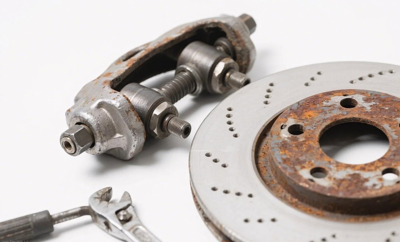
Chemical Failure: Corrosion
Both stainless steel and aluminium depend on a thin oxide layer. This layer is invisible. This layer forms naturally and protects the metal underneath. However, a surface defect can break that layer. Now the bare metal is exposed.
Moisture finds it. So do chemicals. Corrosion starts in that tiny pit and spreads. It spreads beneath the surface, out of sight. By the time you notice it, the damage is already done. Even a single scratch can cause a perfect part to rot.
Assembly Rejection
Sometimes the problem is immediate. You try to assemble parts, and they won’t go together. An interference fit needs a controlled surface. If the peaks are too high, the shaft jams halfway into the bearing. It won’t seat. It won’t move. The assembly line stops. This goes beyond mere surface defects.
And sometimes it’s just looks. Consumer products and automotive parts need eye appeal. A rough surface on a dashboard trim or a phone housing gets rejected. The customer sees it. They return it. They tell others. Aesthetic defects still cost you orders.
Every defect is a liability. Some surface defects next week. Others next year. But they all fail eventually.
How to Fix and Prevent Surface Defects?
Here is the practical part. You see the surface defect. Now fix it. Work through this list in order.
The “First Check” List
Start here before you change anything else.
- Check tool sharpness. A dull tool can ruin finishes. Replace it if necessary. See if the problem goes away.
- Check tool runout. Spin the tool and measure the wobble at the tip. The total indicator reading should be under 0.0005 inches. If it is more than this, it means that your holder is dirty or your collet is worn.
- Check for loose fixtures. Grab the part. Push it. Does it move? Tighten everything. A rigid setup solves half of all finishing problems.
Optimization Strategies
For chatter: Reduce tool overhang first. If you can’t, increase the feed rate. More chip load dampens vibration. Some machines have spindle speed variation. Turn it on. It breaks up harmonic resonance.
For burrs: Use a sharp tool. That’s non-negotiable. Change your tool path direction. Climb milling reduces burrs on most materials. Add a chamfer tool to your program. Break those edges before they become problems.
For poor finish: Increase spindle speed if you can. Decrease the feed rate per tooth. The best fix is a wiper insert. It has a special geometry that flattens the surface in one pass. Worth every penny for the finished work.
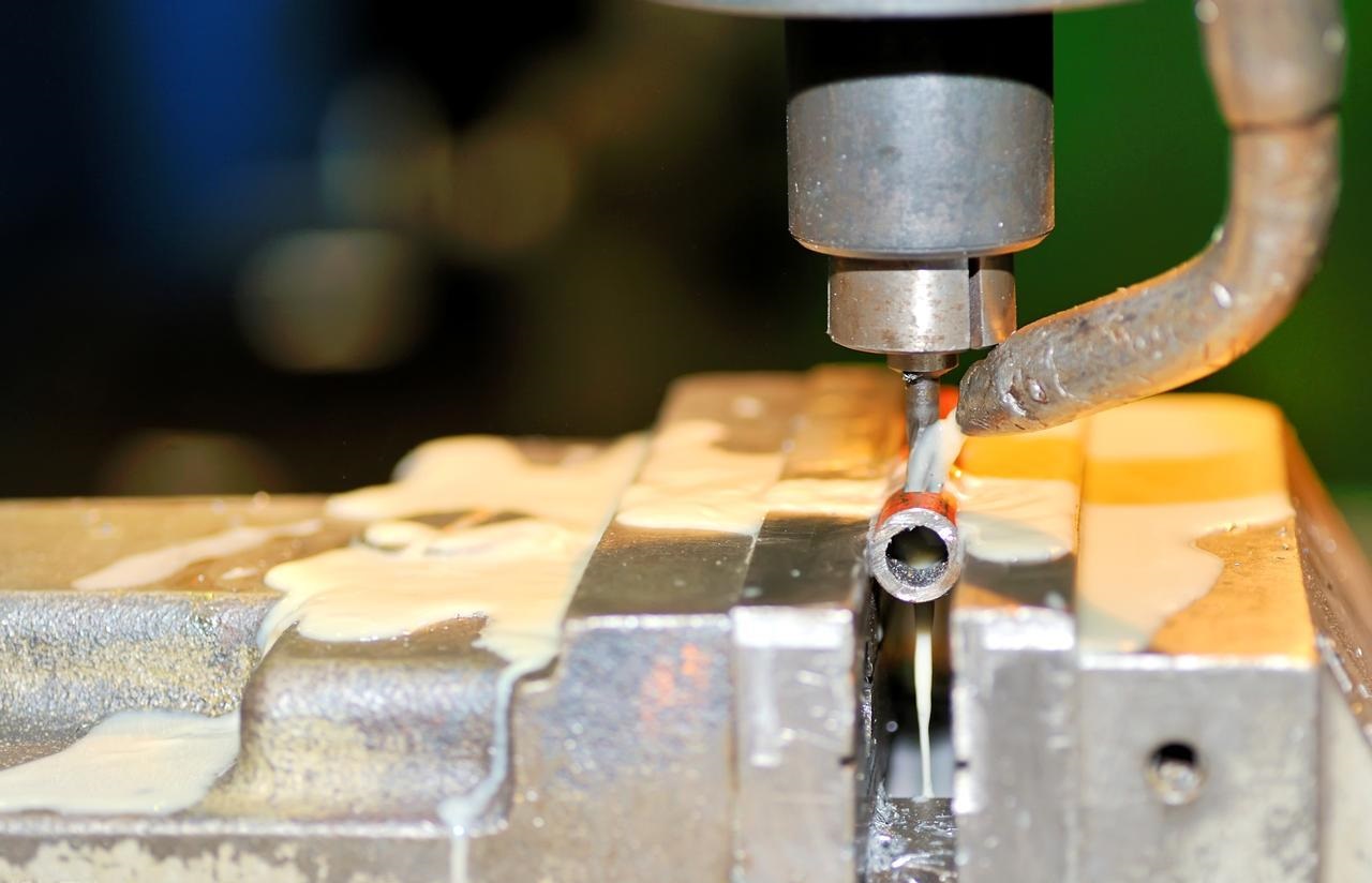
For heat problems: Check your coolant. Is the concentration correct? If it’s too weak, it won’t cool properly. If it’s too strong, it won’t lubricate. Check the pressure at the tool tip. You need a flow of coolant where the cutting is happening, not just everywhere else.
The Role of CAM Software
Your programming choices matter as much as your machine settings.
Use trochoidal milling. Adaptive clearing keeps radial engagement low and constant. The tool never takes a full-width cut. Less engagement means less heat and less deflection. Better finish follows.
Smooth your corners. Sharp direction changes in the tool path jerk the machine. Jerks leave marks. Use radiused corners in your CAM. Let the tool flow around turns. Lead-in and lead-out moves should be arcs, not straight plunges.
The machine follows what you tell it. Tell it to move smoothly, and it will. Tell it to jerk around, and your surface will show every hesitation.
Conclusion
A surface finish is not just for decoration. It is a performance specification. Treat it as such.
Every mark on a part tells a story. For example, chatter marks mean that your setup lacks rigidity. Burrs mean your tool is blunt. Tears mean your speeds are incorrect. The surface is honest. It reveals exactly what is working and what is broken.
Parts fail at the surface. Cracks start there. Corrosion starts there. Leaks happen there. If you ignore the finish, you’re ignoring the part’s future. A smooth surface isn’t just attractive. It’s stronger, too. It lasts longer. It works as designed.
When you come across a machine with a surface defective part, run through the checklist in your head. Check the tool first. Is it sharp and running true? Next, check the speed. Is the balance right between RPM and feed? Thirdly, check the rigidity. Is anything loose? Finally, check the path. Does the CAM move make sense?
Tool, speed, rigidity, path. One of these is wrong. Find it, fix it, and get the next part right.
Why Choose NOBLE for Precision CNC Milling?
You just read about everything that can go wrong on a surface. Chatter, burrs, tears, heat damage. Knowing the problem is one thing. Having a partner who prevents it is another.
Engineering Excellence, Delivered
NOBLE is a precision manufacturing partner built on eliminating those exact surface defects. We don’t treat surface finish as an afterthought. We treat it as a core specification.
Our mission is simple. We don’t just machine parts. We engineer confidence. Every component leaving our floor meets rigorous standards for form, fit, and function. The surface tells the story. We make sure it’s the right one.
Our Core Capabilities
Advanced CNC Milling & Turning. Our fleet runs multi-axis machining centers. Complex geometries don’t scare us. Tight tolerances are routine. We have the iron to hold rigidity and the controls to execute precision.
Surface Finish Expertise. We hit the numbers consistently. Standard work at 3.2 µm Ra. Mirror finishes below 0.4 µm Ra when your application demands it. We know what speeds, what tools, and what paths deliver those results.
Material Versatility. Problem materials are our specialty. Aluminum 6061 that gums up? We handle it. Stainless 304 and 316 that work harden? We know the feeds. Titanium that burns? We have the coolant strategy. Engineering plastics that move? We fix them right. If it’s prone to surface defects, we’ve already solved it.
Our Quality Assurance Process
Inspection Protocols. We don’t guess. We measure. CMMs verify every critical dimension. Surface roughness testers prove the finish. Defects get caught here, not at your assembly line.
Process Control. Prevention beats inspection. We optimize speeds, feeds, and tool paths before the first chip falls. Chatter gets engineered out. Burrs get designed away. The machine runs right from the start.
Experienced Machinists. Software helps. Machines cut. But people solve problems. Our team has the years to look at a part, hear a cut, and know what needs to change. They troubleshoot in real time. They perfect the process. That skill is something no machine can replace.
When surface finish matters, when defects aren’t an option, that’s when you call NOBLE. We build confidence into every part.

FAQ
What is the difference between Ra and Rz?
Ra is the average roughness across a measured length. It smooths out the peaks and valleys into one number. Think of it as the overall texture. Rz looks at the extremes. It measures the average height difference between the five highest peaks and the five lowest valleys. Ra tells you what most of the surface feels like. Rz tells you about the flaws that might cause seal leaks or stress cracks.
Can a bad surface finish be welded over?
You can weld over it. But you shouldn’t. A contaminated or rough surface traps oils, oxides, and debris. Weld over that, and you get porosity, lack of fusion, or weak spots. The fix is to machine or grind the bad surface off first. Start with clean, sound material. Then weld.
Why does my aluminum part look “gummy”?
Aluminum is soft and sticky. When your tool gets dull, it stops shearing the material and starts pushing it. That push smears the surface instead of cutting cleanly. You see tearing, built-up edges, and a general gummy appearance. The fix is a sharper tool, higher surface speeds, and good chip evacuation. Sometimes a polished flute helps. Aluminum wants to be cut, not rubbed.
How much overhang is too much for an end mill?
The general rule is 4:1. Length to diameter. A half-inch tool should stick out no more than two inches from the holder. Push past that, and you invite chatter, deflection, and broken tools. For finishing passes, keep it even shorter. Every millimeter of overhang beyond 4:1 multiplies your problems.
What surface finish can NOBLE guarantee on machined parts?
We deliver consistent results across a range. Standard production holds 3.2 µm Ra without extra effort. When your design demands more, we hit 1.6 µm Ra routinely. For critical applications like sealing surfaces or cosmetic components, we achieve mirror finishes below 0.4 µm Ra. Our CMM and surface roughness testers verify every claim. Tell us what you need. We’ll hit the number.