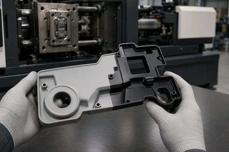
Two-color injection molding injects two materials — or two colors of the same material — into one mold within a single machine cycle, so the finished part comes out of the tool already multi-material. That single change removes several downstream operations at once: no adhesive or snap-fit assembly to join a soft grip to a rigid housing, no painting or pad printing for a second color, no separate lens bonded into a window opening, and no label that can wear off a key. Soft-touch handles, sealed interfaces, permanent two-color legends and light-transmitting windows can all be molded in one cycle.
The trade-off is that everything is decided earlier and more expensively. The resin pair must be fixed before steel is cut, the tool needs two cavity sets and precision shutoffs, and the press needs a second injection unit. This guide follows that decision chain in order: the terminology, the cycle and the main mold configurations, how to pair resins, the design rules to apply before tooling release, the failure modes that show up in production and how they are controlled, and how two-color molding compares with two-tool overmolding, insert molding, decoration and welding. It closes with guidance on judging fit by part and volume, the prototype-to-production path, and how NOBLE supports two-color injection molding projects.
What Is Two-Color הזרקה and How Do the Terms Relate?
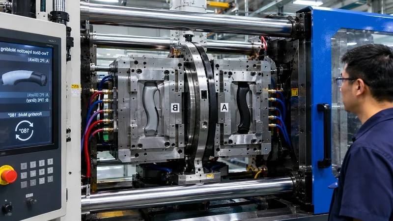
Two-color injection molding is a multi-material injection process in which a first material is injected into a cavity, the mold then indexes, rotates or slides, and a second material is injected over or beside the first while the part stays inside the tool. The first shot forms the substrate — usually the rigid structural component — and the second shot adds a contrasting color, a soft elastomer, or a transparent window. The result is a single part with no assembly step.
Two-shot, 2K, dual-shot and multi-material molding: one family, different emphasis
Two-shot, dual-shot and 2K are near-synonyms for the same sequential two-material process, and a supplier may use any of them for the same quotation. The emphasis differs slightly. “Two-color” describes the visual outcome — two colors in one part. “Two-shot” describes the sequence — two injection steps. “2K” is the shorthand for two components (Komponenten) common in European tooling and machine literature.
“Multi-material” or “multi-component” molding is the broader umbrella. It covers two-component work but also extends to three or more components and to variants such as sandwich or co-injection molding, where an outer skin material and a core material — often recycled, foamed or filled — are injected through the same tool. In sandwich molding the cavity is first partially filled with the skin material and the core material is then injected into the center of the skin; alternating components of different colors can also be used to produce marbling effects.
A single part may legitimately be described by several of these terms at once, so it is worth confirming with your supplier which configuration and which machine the quote assumes rather than relying on the label.
What two-color molding is not
Three processes are often confused with two-color molding, and the distinction matters because each carries a different tooling bill and a different bond mechanism.
A single-shot part that is later painted, printed or laser-marked is not two-color molded. The second color is applied after ejection, in a separate operation, and it sits on the surface rather than being molded into the part.
Two-tool overmolding uses two separate molds. The substrate is molded in the first tool, then transferred — by hand or robot — into a second mold where the overmold resin is injected. The part leaves the tool between shots, which is why contamination control and re-fixturing tolerance become part of the process.
Insert molding encapsulates a pre-made component, usually metal, in a single plastic shot. There is no chemical bond between metal and thermoplastic and none is needed: retention is purely mechanical, achieved by plastic shrinkage gripping knurling, undercuts or grooves on the insert.
Two-color molding differs from all three in that both materials are injected in one machine cycle and the part never leaves the tool between shots. That is the source of its tightest registration and its strongest chemical bond — and of its highest tooling cost.
The Two-Color Injection Molding Cycle and Mold Configurations
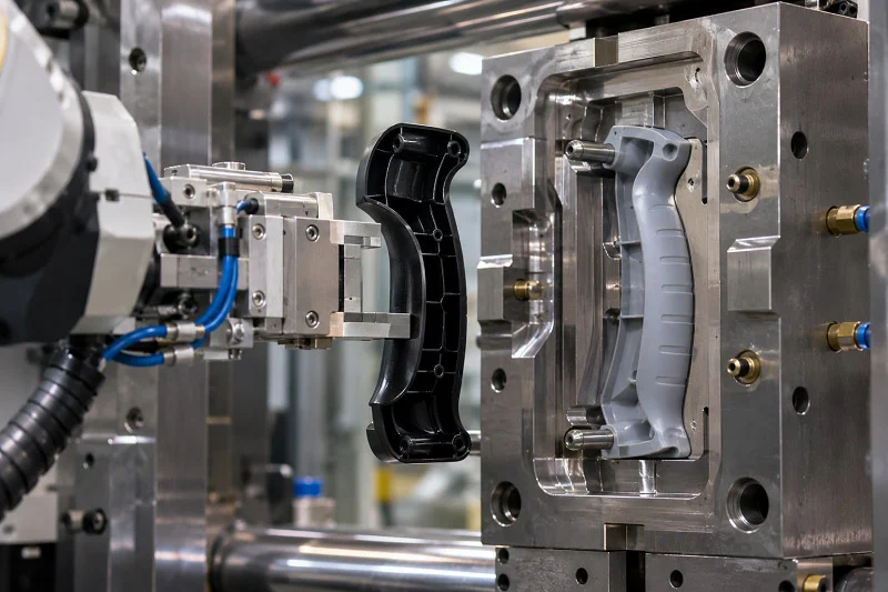
Understanding the cycle explains why two-color molding is quoted the way it is, and why cycle time is not simply double a single-shot cycle.
Step by step through a two-shot cycle
The first shot is injected into its cavity and cooled. The mold opens, and the mold half carrying the first-shot preform indexes, rotates or slides into alignment with the second-shot cavity steel. The second shot is then injected over or beside the preform, while the first shot for the next part is injected into the now-free first-shot cavity. The completed part — the one carrying both materials — is ejected, while the preform that just received its second shot stays in the tool.
After start-up, the two shots therefore run concurrently rather than sequentially: in each cycle, one station is molding a first shot while another is overmolding the previous cycle’s preform. On a rotary-platen tool, the rotating half carries identical first-shot cavities, while the stationary half carries both the first-shot and second-shot cavities; the ejector side has two sets of ejector plates because only the parts with both materials are ejected each cycle.
Mold and machine configurations
The main configurations differ in how the preform is presented to the second shot, and that in turn decides which part geometries each can handle.
Rotary platen / turntable. The mold half is rotated on a movable clamping plate, in a two-stroke or four-stroke cycle, after the first component has been injected and cooled. The preform is then filled with the second component while the first component is simultaneously injected into the free cavity. This suits parts where the preform is partially or unilaterally exposed, and is used for unilateral overmolding of large quantities. A simpler variant rotates a vertical platen on a horizontal axis; the more complex “cube mold” or “spin stack” rotates a center stack with two or four faces on a vertical axis and is the costliest version.
Index plate. The first component is injected into a cavity that is part of the index plate; the preform is pushed out and rotated, and by moving the index plate back the preform is placed on the other mold core and overmolded on both sides. This suits preforms that must be free on one side at the top and partially free at the bottom.
Sliding split. Only one cavity with a core-pull function is required: after the preform is injected and cooled, the separating slide retracts to create a second cavity that the second component fills. Because it needs just one cavity, the process is simple and cost-effective, and suits preforms that must be partially released.
שולחן הזזה. The mold has a core side and two cavity sides; after the first component is injected, the mold opens and the core side is pushed onto the second cavity half. It suits partially or unilaterally exposed preforms and is particularly suitable for unilateral overmolding of small quantities in prototype production or small series.
לְהַעֲבִיר. A robot removes the preform from the first cavity and inserts it into a second cavity, where the second component is injected after the mold closes while the other cavity is already being filled with the first component. This covers designs in which the preform must be free on both sides, and can span all design grades.
Sandwich / co-injection. The cavity is partially filled with the skin material and the core material is injected into the core of the outer material, producing a skin-and-core structure rather than a side-by-side or overmolded geometry.
Rotary platen, movable-core and overmold variants also exist as a family; the first two require a second injection unit, two runner systems and two processes, while the overmold variant in most cases involves two separate molds.
Choosing Materials for Two-Color Injection Molding
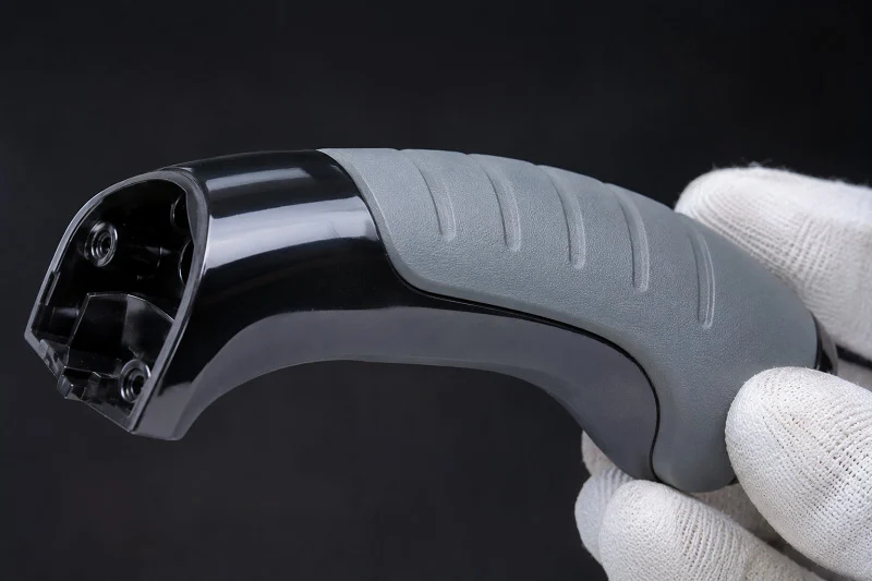
Material selection is the decision that determines whether the part holds together, and it has to be finalized before mold design begins — changing the pair later is extremely costly.
Chemical bonding versus mechanical interlocking
Two-shot material bonding works through two mechanisms. Chemical adhesion happens when the second material partially melts and interdiffuses with the still-semi-molten surface of the first shot at the molecular level, forming a bond that can be as strong as either material alone. This is why two-shot molding relies heavily on chemical bonding: the second material is injected onto the still-warm first shot, and the window for a strong bond is narrow.
Mechanical interlocking is the alternative or the backup. When the overmold resin flows into holes in the substrate — particularly holes that are dovetailed to widen at the bottom — the cooled material locks to the substrate. Wrapping the overmold around the substrate, or increasing interface area with grooves, pickets, posts or bosses, achieves the same effect. A porous substrate provides tiny holes into which an elastomer can migrate.
Some pairs bond well chemically; others need mechanical features. A TPE formulated to bond polypropylene will not bond polycarbonate, and a standard styrenic TPE will not bond PP at all unless the grade is PP-based. Matching the TPE chemistry to the substrate family is therefore the first material decision, and it is made against the compounder’s published adhesion tables rather than by trial.
Common substrate and overlay pairings
The pairings below are the combinations most consistently reported in production, with bond quality and typical applications as published in compatibility guidance.
| Substrate (Shot 1) | Overlay (Shot 2) | Bond quality | יישום אופייני |
| ABS | Styrenic TPE | מְעוּלֶה | Soft-grip tools, consumer electronics |
| PC | Styrenic TPE | מְעוּלֶה | Medical devices, power tool housings |
| תערובת PC/ABS | Styrenic TPE | מְעוּלֶה | גימור פנים הרכב |
| PA6 / PA66 (nylon) | Polyamide-based TPE | טוב עד מצוין | Under-hood automotive connectors |
| PP | Olefinic TPE / TPV | טוב | Automotive seals, consumer packaging |
| POM (אצטל) | Modified TPE | Fair — needs mechanical lock | Gear assemblies, locking mechanisms |
| ABS | אס"א | Excellent (same family) | Outdoor equipment, two-color parts |
| PMMA | ABS | טוב | Transparent windows over colored bodies |
For automotive work, PA6 or PA66 paired with a polyamide-based TPE is the standard: the nylon substrate handles heat and chemical exposure while the TPE overlay provides sealing or grip, and the TPE must be specifically formulated for polyamide adhesion rather than a generic styrenic grade. Thousands of possible substrate and overmold combinations exist, and material suppliers can identify specialty grades where a standard pair does not meet the performance requirement.
One structural caution: amorphous over semi-crystalline combinations such as PC over PA6 can work, but the shrinkage differential creates internal stress at the interface. Semi-crystalline materials shrink more during cooling — roughly 1.5–2.5% versus 0.4–0.7% for amorphous resins — which puts shear stress on the bond line. It is manageable if designed for, but it is a common source of late-stage warpage.
Melt temperature and shrinkage differences
The first shot must survive the second shot’s heat. The second-shot material has to be processable at a temperature that will not degrade the first shot but is hot enough to promote interdiffusion; a processing-temperature gap of roughly 30–40°C between the two materials is commonly cited as the working range. A melt temperature too low to soften the substrate surface is one of the standard causes of a failed bond.
Shrinkage is the second quantity to compare. Mold shrinkage is the geometric reduction in part size relative to the mold cavity, measured per ASTM D955-08 at 24–48 hours after demolding. Warpage is the distortion induced by inhomogeneous shrinkage, which arises in three ways: shrinkage differences in different directions due to material anisotropy, region-to-region variation from non-uniform pressure and temperature, and non-uniform shrinkage across the thickness from differential cooling on opposing mold faces. In a two-color part, the two resins’ differing shrinkage adds a fourth source, which is why material pairing and warpage control are handled together in the risk section below.
Design Rules Before נוסע לשחרר
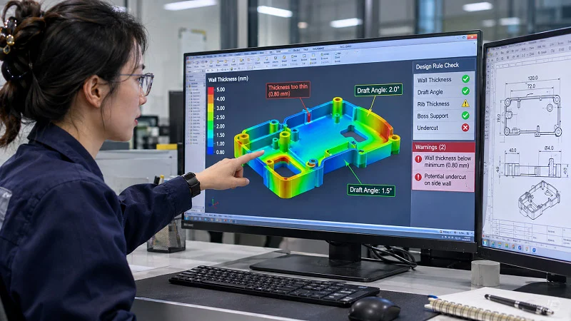
The rules below can be applied before steel is cut. They are grouped by the feature they govern, and each one is cheaper to fix on a drawing than in a tool.
Wall thickness, ribs and transitions
Keep wall thickness as consistent as possible and core out thick masses rather than leaving solid sections. Heavy bosses and thick ribs are the standard design causes of sink marks and internal voids, because thick sections cool unevenly; replacing solid mass with ribs and gussets reduces both. Uneven wall thickness, cooling imbalance and high shrink are the standard causes of warping, so gradual transitions between thick and thin regions do the same work for dimensional stability.
Draft, shutoffs and parting lines
Draft is what lets the part release cleanly; substrate walls that will carry an overmold are commonly drafted 1 to 1.5 degrees per side. Shutoffs control flash, and poor shutoff design or a difficult parting line is the usual cause of thin excess plastic at edges. Parting-line placement is a cosmetic decision as much as a technical one, since the line will be visible on the finished part.
In two-shot tooling, the shutoff that matters most is “crush”: a raised area of second-shot cavity steel that presses into the first shot to prevent the second-shot material from flashing or bleeding onto the first-shot surface where it does not belong. Crush is typically 0.003–0.005 in. In areas where the first shot has thicker wall stock, extra crush may be needed to compensate for the greater shrinkage — achieved either by adding steel to the second-shot shutoff or by adding first-shot material through removing steel.
Bonding areas and mechanical interlocks
Where a chemical bond is expected, the second shot must contact a clean, hot first-shot surface. Contamination, mold release residue, skin contact during handling, or a delay long enough for the interface to cool before the second shot lands will all defeat an otherwise compatible pair.
Where a chemical bond is not available, design the interlock: holes (dovetailed where possible), ribs, undercuts, grooves or posts at the interface. To prevent peeling, avoid exposed edges of the overmolded material; a raised edge of substrate material can protect the edges of the elastomer where peeling would otherwise begin.
Two practical notes on the soft layer. Thin overmold layers — typically below 0.40 in. (10 mm) — will feel hard regardless of material choice, which is why consumer products often use rows of taller ribs to increase perceived thickness while reducing material volume. And durometer is not a reliable measure of perceived softness: flexural modulus, which measures resistance to bending, is the better indicator, with a lower flexural modulus feeling softer.
Gate placement and registration tolerance
Gate location affects fill for both shots. Thin walls, long flow paths and poor gate location are the standard causes of short shots, and a gate that lets resin enter too quickly into open space produces jetting. Gate position also has to respect the second-shot cavity: the first-shot part must be fully supported in the second-shot cavity against cavity pressure, because the second shot applies thousands of pounds of plastic pressure against the first-shot plastic, not just against steel. In practice this means no unsupported feature longer than about three times its own thickness, with ribs or undercuts behind the faces that will receive the overmold.
Registration is where two-color tooling earns its cost. Two-shot tooling shares one tool reference, so both materials are positioned by the same steel and registration is the tightest available. Two-tool overmolding stacks tolerance through re-fixturing between the two molds. On rotary-platen tools, locators on the mold and the machine platens are critical to keep the mold exactly on center of the rotary platen; if it is off center, a 180° rotation can damage leader pins, bushings and shutoffs.
Production Risks and How They Are Controlled
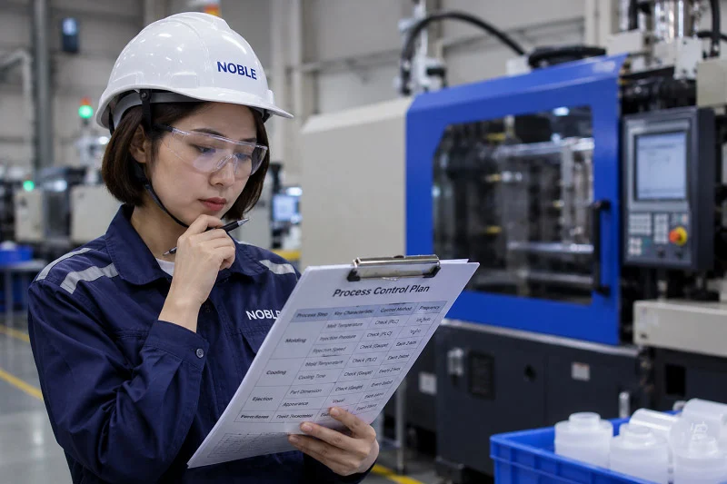
The failure modes in two-color molding are well characterized, and each has a standard set of controls that belong in the validation plan rather than in a reaction to scrap.
Warpage from shrinkage mismatch
Warpage is distortion induced by inhomogeneous shrinkage, and in a two-color part the two resins’ differing shrinkage is an additional source on top of the directional, region-to-region and through-thickness variation that any molded part can show. Amorphous-over-semi-crystalline pairs are the clearest case, since the shrinkage differential puts shear stress on the bond line and can surface as late-stage warpage.
Controls are structural and thermal rather than cosmetic: balanced wall thickness and gradual transitions, balanced cooling on both mold faces, a material pair whose shrinkage difference is understood and acceptable, and mold-flow simulation before steel is cut. Simulation is the cheap place to discover that a geometry cannot hold flat.
Delamination and weak bond
Bond failure can appear after thermal cycling even when the part passed at sampling, which is why bond validation should include thermal cycling rather than a single pull test on a fresh part. The causes are a melt temperature too low to soften the substrate surface, incompatible TPE chemistry, a wet or contaminated substrate, mold release residue, handling during transfer, or a delay long enough that the interface cools before the second shot lands.
The failure mode tells you which. Cohesive failure — where the TPE tears before the interface lets go — is the preferred result, because it means the joint is stronger than the elastomer. Adhesive failure, where the TPE peels clean off the substrate, points at the interface and therefore at chemistry or process. Published peel testing per ASTM D6862 treats above about 15 lbf per inch of width as excellent adhesion and at or below about 10 lbf per inch as poor. Where the chemistry is marginal, mechanical interlocks act as a backup, and bonding checks belong at the sampling stage.
Short shots, interface flash and process-window discipline
Short shots come from thin walls, long flow paths and poor gate location, and are addressed in the tool and the fill pattern rather than by raising pressure indefinitely. Interface flash comes from insufficient crush, inadequate support of the first shot, poor shutoff design, or hydraulic cylinders that are not robust enough to resist cavity plastic pressure.
The subtler risk is process discipline. Because two shots interact, molders often process the first shot to address issues with the second-shot process, or the reverse. That narrows the process window and raises scrap risk: crush, support, deflection and undersized cylinders can all be processed around, at the cost of quality margin. Tonnage is also partly consumed in rotary tools because the cavities sit off-center — first shot on one half, second shot on the other — so the full machine tonnage is not available to compensate for cavity plastic pressure.
Two-Color Molding Compared with Other Processes
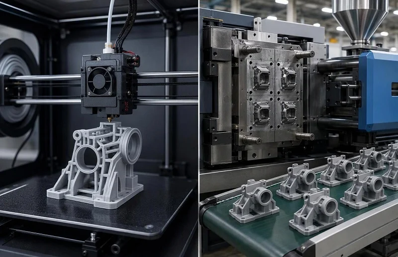
The alternatives to two-color molding are not inferior versions of it; they are different positions on tooling cost, cycle structure, bond strength and volume economics.
Overmolding (two-tool) and insert molding
Two-tool overmolding uses two separate molds and standard presses, with the substrate transferred between tools by hand or robot. It is the most flexible of the routes: the overmold tool can be changed or rebuilt without scrapping the substrate tool, the two shots can run on different presses or even different sites, and it suits development work, new product introduction, and volumes that will not amortize a two-shot tool. The costs are a transfer step, contamination and labor risk between shots, and looser registration because re-fixturing stacks tolerance.
Insert molding uses one mold plus insert locating features and encapsulates a pre-made component, usually metal, in a single plastic shot. Retention is purely mechanical — knurling, undercuts, grooves — with no chemical bond. Tooling is the lowest of the three, but insert loading is a per-cycle operation: at low volume an operator loads inserts into the open tool every cycle, which introduces person-to-person variation in seating and orientation; at volume, robots or bowl-fed loaders restore repeatability and remove the operator from the cycle.
Two-shot molding uses a dedicated press with two or more injection units and one 2K tool with two cavity sets and tight crush and shutoff control. It carries the highest tooling cost and the lowest per-part cost at volume, the strongest chemical bond because the interface stays hot, and the tightest registration because both shots share one tool reference.
| תכונה | Two-tool overmolding | הכנס דפוס | יציקה דו-פעמית |
| What is joined | Rigid plastic substrate plus a second plastic, usually TPE or TPU | Pre-made component, usually metal, encapsulated in plastic | Two plastics in one part, often rigid plus elastomer |
| מכונה | Two standard presses, or one press and two molds | One standard press; vertical clamp common | Dedicated press with two or more injection units |
| עובש | Two separate molds | One mold plus insert locating features | One 2K tool, two cavity sets, tight crush and shutoff control |
| מחזור | Two cycles plus a transfer step | One cycle plus insert loading every shot | One combined cycle; shots run in parallel after start-up |
| מנגנון קשר | Chemical melt adhesion plus mechanical interlock where needed | Purely mechanical encapsulation | Chemical melt bond, strongest because the interface stays hot |
| Handling between steps | Part transferred by hand or robot | Insert loaded every cycle | None; the part never leaves the tool |
| עלות יחסית של כלי עבודה | אמצע | הנמוך ביותר | הגבוה ביותר |
| Relative per-part cost at volume | אמצע | Rises with insert-loading labor | הנמוך ביותר בווליום |
| Registration between materials | Looser; re-fixturing stacks tolerance | Set by how the insert is located | Tightest; both shots share one tool reference |
| שימוש אופייני | Grips, seals, soft-touch at low and mid volume | Threaded inserts, terminals, pins, bushings | High-volume grips, permanent legends, cosmetic trim |
Painting, printing and in-mold decoration
Decoration processes add steps after molding, whereas two-color molding produces color, texture and legends in the mold. Painting and pad printing apply the second color to a finished part and carry per-part processing cost plus a durability limit tied to the coating or ink; two-color molding has no such wear surface because the color is the material.
In-mold decoration (IMD) is a separate family — in-mold labeling (IML), in-mold film (IMF) and in-mold transfer (IMR) — in which a film or printed ink is placed in the cavity and bonded during molding. IMD is itself sometimes combined with two-color molding, and the combination is more demanding than either alone. Two-color IMD quality depends on product structure, adhesive inlet design, material selection for both the first and second color components, film processing technique, film thickness and injection parameters, and the characteristic defects include ink washout, weak adhesion between color layers, surface concavities and indistinct textures. Ink washout in two-color IMD is primarily caused by suboptimal mold inlet design, with film selection and film thickness as secondary contributors; the second injection adds complexity because the melt contacts the top of the film before potentially dispersing the ink at the bottom. Where the film material matches the first and second color components — PC for all three, for example — bonding strength improves.
Ultrasonic welding and assembly
Welding joins separately molded parts and adds an assembly step plus joint design constraints: the two components each need a simple single-material tool, the materials do not have to be chemically compatible, and either can be revised alone. What it cannot do is remove the joint. Two-color molding eliminates both the assembly operation and the joint, which is why it is the standard answer for permanently legible keys and cosmetic trim where no parting-line witness is acceptable. The trade-off is tooling cost and the restriction to material pairs that will bond.
A volume and economics framework
The cost logic is ordinary and worth stating plainly. Two-color tooling carries the highest upfront cost — two cavity sets, precision shutoffs and a dedicated press — so it pays back at higher volumes. Two-tool overmolding sits in the middle: two tools on standard presses. Insert molding has the lowest tool cost but rising labor per part as volume grows. Decoration adds per-part processing, and welding adds an assembly operation.
The practical decision sequence runs: bond requirement first (does the joint need chemical adhesion, or will mechanical retention do?), then material pair, then volume, then tooling budget, then registration tolerance. Answering them in that order avoids the common error of selecting a process before the bond and material pair are settled.
Does Two-Color Injection Molding Suit Your Part and תכולה?
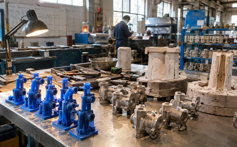
Two-color molding is the right answer for a specific combination of part function and volume, and the signals are recognizable before a quote is requested.
קריטריוני התאמה
Four signals favor two-color molding. First, a genuine two-material function: a soft grip, a seal, a window, or a permanent two-color legend that cannot wear off. Second, a bond that must be strong and consistent, where chemical adhesion on a hot interface is an advantage rather than a risk. Third, registration that must be tight — cosmetic trim where no parting-line witness is acceptable, or keys and legends that must stay in position. Fourth, volume high enough to amortize the tool and the dedicated press.
When the design is still moving, or the volume will not amortize a 2K tool, two-tool overmolding is usually the better fit. When the second material is metal rather than plastic, insert molding is the relevant comparison.
מאב טיפוס ועד לייצור המוני
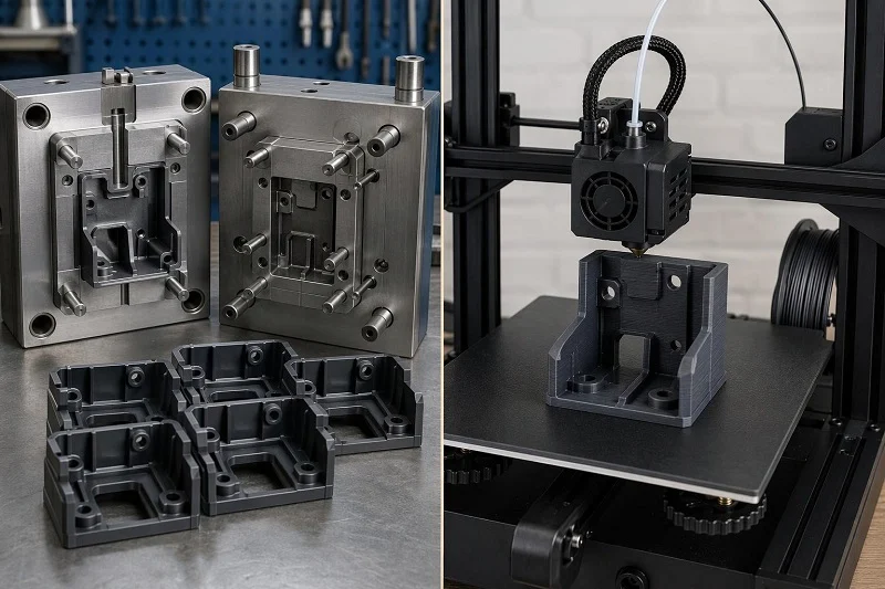
A realistic path runs through six stages. Concept and material pairing come first, settled against adhesion data rather than trial. DFM review and mold-flow simulation follow, to test fill, cooling balance and warpage before steel is committed. Prototyping comes next: multi-material soft-touch parts can be prototyped in additive materials that approximate a rigid-plus-elastomer assembly, which is usually enough to test grip geometry and ergonomics, or a sliding-table tool can be used for small series where real two-shot parts are needed early. T1 sampling then validates dimensions and bond performance, including thermal cycling. Process-window establishment follows, with both shots tuned together rather than one compensating for the other. Production then runs with in-process inspection.
Bond validation belongs in that path, not after it. The most reliable pre-tooling test is to mold flat plaques of both materials in sequence using a test mold, then perform peel testing per ASTM D903 and cross-hatch adhesion testing per ASTM D3359. Most TPE suppliers also publish adhesion data sheets showing measured peel strength against common substrates, and those should be requested before material selection is finalized.
Choose NOBLE to Support Your Two-Color Injection Molding Projects
NOBLE is a Sino-British joint venture and a Chinese manufacturing partner awarded by the government as a “National High-tech Enterprise.” With over 10 years of experience, NOBLE provides one-stop custom manufacturing from prototyping to production, and our engineering and processing capabilities support customers through both prototyping and batch production for two-color injection molding projects.
Our quality management is certified to ISO 9001:2015 and ISO 13485:2016. The second certification matters for teams developing medical devices and surgical instruments, where two-color molding is used to combine different hardnesses and colors in one component.
We provide a full service from design to assembly — not production alone. That scope means the decisions this guide describes can be handled inside one project: material pairing and DFM review before tooling release, prototype parts to test grip geometry and ergonomics, mold-flow simulation and sampling, and production with inspection.
Supporting capabilities, as first-party facts about our operations:
- Rapid lead time. Your parts can be finished rapidly within 7–10 days with the support of comprehensive CNC software and experienced engineers.
- תמחור בזמן אמת. ניתן להציע הצעת מחיר מהירה ומקצועית תוך 24 שעות לאחר הגשת בקשת הצעות מחיר (RFQ) עם המידע הנדרש.
- In-house capabilities. Extensive capabilities in-house meet requirements from design and prototypes through mass production of parts, rather than relying on outsourced orders.
- Sophisticated testing equipment. A full set of inspection equipment and an overall quality control system help ensure prototypes and components are created with high accuracy.
- Industry-leading expertise. Advanced rapid prototyping and rapid manufacturing technology to machine various metal and plastic materials as per stated specifications.
To discuss a two-color injection molding project, submit an RFQ with the part information needed and our team will respond with a quote and a recommended path from prototype to production.
FAQs of Two-Color Injection Molding
What is the difference between two-shot, 2K, dual-shot and multi-material molding?
Two-shot, 2K and dual-shot are near-synonyms for the same sequential two-material process in one machine cycle. Multi-material or multi-component molding is the broader umbrella, covering two-component work plus three-or-more-component variants and sandwich/co-injection. “Two-color” emphasizes the visual result; “two-shot” emphasizes the number of injection steps.
Which mold configuration suits which part?
Rotary platen suits partially or unilaterally exposed preforms at high volume. Index plate suits preforms free on one side at the top and partially free at the bottom, with overmolding on both sides. Sliding split is the simple, cost-effective choice where the preform must be partially released. Sliding table suits prototypes and small series with unilateral overmolding. Transfer covers designs where the preform must be free on both sides. Sandwich/co-injection produces a skin-and-core structure.
Which resin pairs bond chemically, and which need a mechanical lock?
ABS, PC and PC/ABS with styrenic TPE bond excellently; PA6/PA66 with polyamide-based TPE bond well to excellently; PP with olefinic TPE or TPV bonds well; ABS with ASA bonds excellently as a same-family pair; PMMA with ABS bonds well. POM with modified TPE is only fair and needs a mechanical lock. A standard styrenic TPE will not bond PP at all unless the grade is PP-based.
What are the key design rules before tooling release?
Consistent wall thickness with cored-out masses and ribs instead of solid sections; adequate draft (commonly 1–1.5 degrees per side on substrate walls carrying an overmold); crush of typically 0.003–0.005 in. on the second-shot shutoff, with extra crush where the first shot is thick; full support of the first shot against second-shot cavity pressure, with no unsupported feature longer than about three times its thickness; and mechanical interlocks wherever the chemical bond is not assured.
How are warpage and delamination controlled?
Warpage is controlled by balanced walls and gradual transitions, balanced cooling, a material pair with an understood shrinkage difference, and mold-flow simulation before tooling. Delamination is controlled by correct material pairing, keeping the first-shot surface hot and clean, mechanical interlocks as backup, and bond checks at sampling that include thermal cycling. Cohesive failure (the TPE tears) is the preferred result; adhesive failure (clean peel) points at chemistry or process.
How does two-color molding compare with overmolding, insert molding, decoration and welding on tooling and volume economics?
Two-color molding has the highest tooling cost and the lowest per-part cost at volume, with the strongest chemical bond and tightest registration. Two-tool overmolding sits in the middle on tooling and per-part cost and is the most flexible for development. Insert molding has the lowest tool cost but rising labor per part at volume. Decoration adds per-part processing after molding. Welding adds an assembly step and joint design constraints.
How do I judge whether two-color molding suits my part and volume?
Look for a genuine two-material function, a bond that must be strong and consistent, tight registration requirements, and volume high enough to amortize the tool. Then follow the prototype-to-production path: material pairing, DFM and simulation, prototype (additive or a sliding-table tool for small series), T1 sampling with bond and thermal-cycle validation, process-window establishment, and production with in-process inspection.