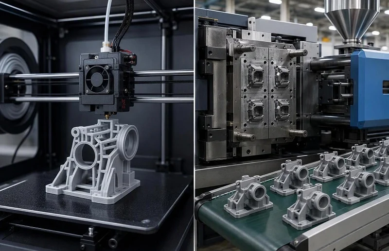
A plastic part rarely moves from a CAD file to a shipping carton in one step. Somewhere between the first design review and the ten-thousandth unit, someone has to decide how the part will actually be made — and for most plastic components the shortlist comes down to 3D printing vs injection molding. Framing that choice as a contest between an advanced method and a traditional one misleads. The two processes carry different cost structures, obey different geometry rules, and are judged against different quality expectations. One charges you for machine time; the other charges you for a tool.
This comparison works through the criteria that decide the route: how each process physically forms a part, what that means for lead time, where the unit-cost curves cross, which geometries each permits, what materials and tolerances you can expect, and which applications each fits. It closes with a decision rule you can apply to your own part — and with the note that the crossover point is specific to your geometry, material and volume, not a fixed number borrowed from a general guide. NOBLE supports both paths, from prototype iterations to production tooling, so the comparison is written for teams that may need either.
দ্রুত তুলনা: 3D মুদ্রণ Vs ইনজেকশন ছাঁচনির্মাণ এক পলকে
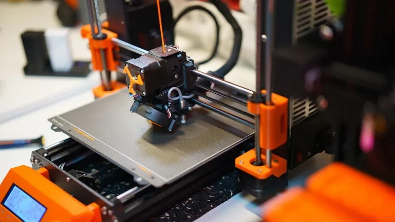
The table below summarises the comparison at the level published process data supports. Treat the figures as capability ranges and reference bands, not quotations for a specific part.
| নির্ণায়ক | 3D প্রিন্টিং | ইনজেকশন ছাঁচনির্মাণ |
| প্রয়োজনীয় সরঞ্জাম | None; a digital file is the input | Yes — aluminium, soft steel or hardened steel mold cut before any saleable part exists |
| Typical lead time to first parts | Hours to days, including post-processing | Tool fabrication of roughly 2–4 weeks (aluminium prototype mold), 4–8 weeks (soft steel or bridge mold) or 8–20 weeks (full production steel mold), then trial shots and qualification |
| Unit cost behaviour | Comparatively flat; each part consumes similar machine time | Falls steeply as one-time tooling amortises over volume |
| Undercuts, internal channels, lattices | Built without draft or split lines; internal channels and lattice structures are routine | Undercuts need side actions, lifters or sacrificial cores; some internal geometries are effectively impossible in a rigid mold |
| Draft and wall uniformity | No draft requirement; orientation-dependent properties and support marks instead | Draft angles, uniform wall transitions and shrinkage compensation are design-time obligations |
| উপাদান পরিসীমা | Process-specific: photopolymers, nylon powders, engineering filaments | Full range of production thermoplastics, including filled and engineering grades |
| সাধারণ সহনশীলতা | Published as-printed ranges vary by process — FDM coarsest at roughly ±0.5% with a floor; SLA and PolyJet finest; SLS and MJF around ±0.3% with a floor | Repeatable, taken from the tool; tight or cosmetic-critical surfaces may still need secondary operations |
| সারফেস ফিনিস | Layer stepping in FDM; grainy matte in SLS and MJF; near-molded smoothness in SLA and PolyJet | Replicates the tool surface consistently across the run |
| সর্বোত্তম-উপযুক্ত আয়তন | Prototypes, low volumes, bridge production, customised parts | Stable designs at volume, where tooling amortises comfortably |
| সর্বোত্তম-উপযুক্ত অ্যাপ্লিকেশন | Iteration, complex or consolidated geometry, patient-matched devices, jigs and fixtures | Production parts needing engineering thermoplastics and consistent cosmetic finish |
One caution governs the whole table: the volume at which molding becomes the cheaper route depends on part size, material, tool complexity, cavitation and cosmetic requirements. Published crossover figures differ widely for exactly that reason, and the sections below explain why rather than offering a single universal number.
How 3D Printing and Injection Molding Actually Work
Every cost, speed and geometry difference later in this article follows from how the two processes physically form a part. Establishing that mechanics first keeps the rest of the comparison grounded.
What Happens In 3D Printing
A 3D printer builds an object by depositing or fusing successive layers of raw material, each new layer attached to the one below until the part is complete. The input is a digital 3D file — a CAD model or, in medical work, imaging data — and no mold, die or other tooling is required. That absence of tooling is what allows a design change to be implemented by editing a file rather than cutting hardware.
Build orientation matters more than newcomers expect. Orientation determines where support structures are needed, how stair-stepping appears on angled surfaces, and how the part’s properties distribute across axes. Support removal, curing and surface treatment are mandatory post-processing steps across additive processes, and they add time and labour to every build. Resolution and speed also trade off directly: thinner layers improve finish but lengthen the build, a constraint that holds across polymer and metal systems alike.
The main route by which printing gains any volume efficiency is build packing. Powder-bed systems can nest many parts in a single build without support material, and packing a build more fully lowers energy consumption per kilogram deposited. That benefit is real but bounded — it improves the economics of a build, not the fundamental per-part machine-time relationship.
What Happens In Injection Molding
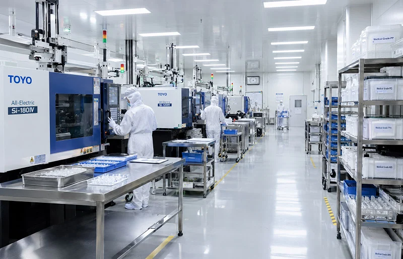
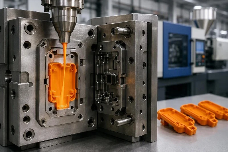
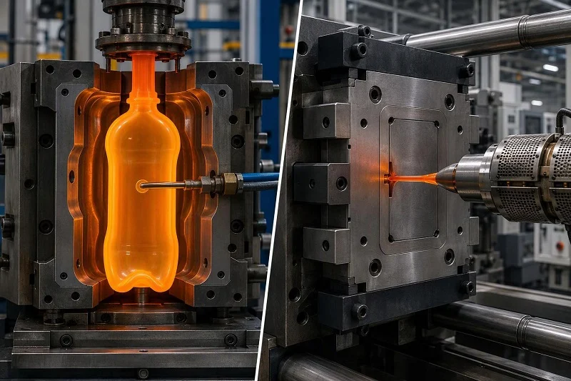
Injection molding fills a closed steel or aluminium mold cavity with molten polymer under high pressure. After the cavity is volumetrically filled, packing pressure is maintained to compensate for shrinkage as cooling begins, and the part then solidifies against the mold walls before ejection. Cooling typically represents the longest portion of the cycle.
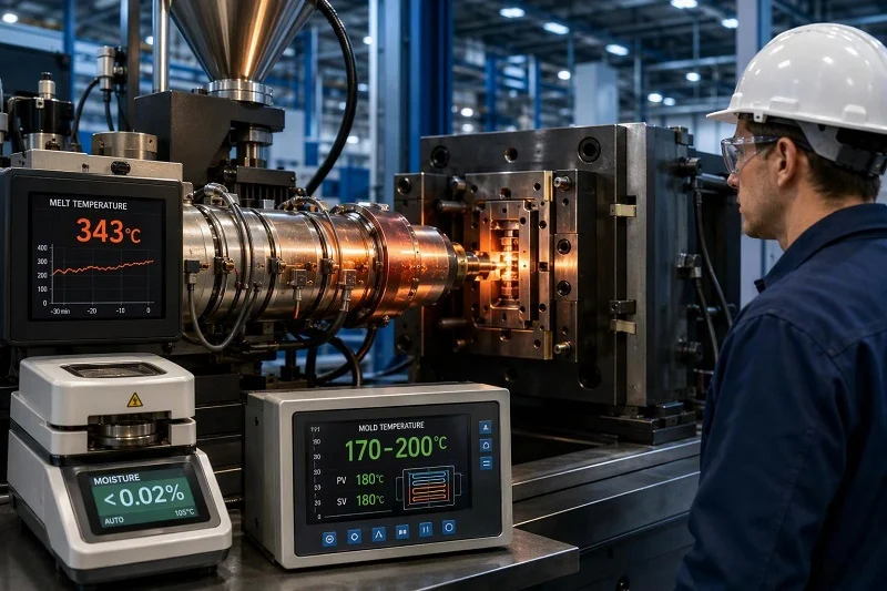
Critically, the tool must be designed and cut before the first saleable part exists. That sequencing is the source of molding’s lead time and its cost structure. It also means defects can originate in two distinct places: some are built into the geometry before the mold is ever cut — wall thickness variation, gate placement, cooling imbalance — while others emerge from temperature, pressure or timing instability on the machine, varying from shift to shift or lot to lot. Stable programs treat molding as a thermal and pressure-controlled system rather than a simple forming step; when control discipline holds, the process delivers exceptional repeatability across long runs.
Why The Mechanics Drive The Economics
Printing has no tooling charge but pays machine time for every part, because each part occupies the build for a comparable duration regardless of order size. Molding inverts this: a large one-time tooling cost buys a short cycle that produces parts cheaply once the tool exists. Nothing in the volume discussion that follows is more than a consequence of that inversion — and it is why the expensive decision in a molding project is the tooling decision, not the molding step.
Process Flow And Lead Time Compared
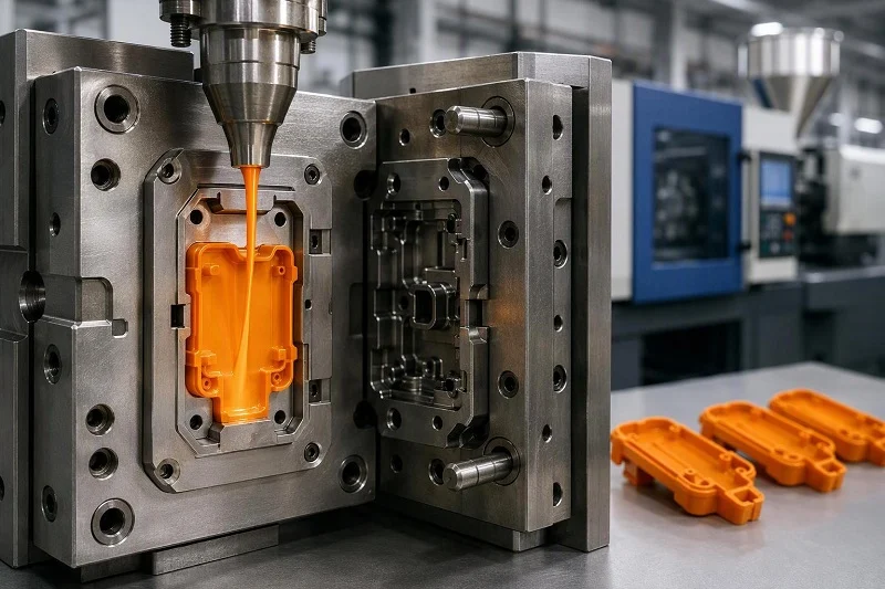
The sequence a project travels through differs as much as the physics. What each step costs in calendar time determines when you hold a part in your hand.
The 3D Printing Workflow: File To Part
The workflow runs from model preparation and orientation through build scheduling, printing and post-processing. Because there is no tool to fabricate, turnaround is measured in hours to days rather than weeks. Design changes between iterations cost only a new file and a new build — no hardware is scrapped. Post-processing is the step that most often surprises schedules: support removal, washing, UV curing and finishing are mandatory and consume labour, and in metal systems sintering, cooling and depowdering can add many hours beyond the print itself.
The Injection Molding Workflow: সাধনী দ্বারা প্রয়োগকরণ Before Parts
Molding runs through mold design, tool fabrication, trial shots and qualification before production begins. Published reference bands put an aluminium prototype mold at roughly 2–4 weeks to fabricate, a soft steel or bridge mold at 4–8 weeks, and a full production steel mold at 8–20 weeks — all before any parts can be produced. These bands vary with tool complexity and supplier capacity, and they sit outside any quoted production window rather than adding neatly to it.
Engineering changes after the tool exists are where molding schedules slip. A modification is possible but costly, and complex revisions can push a timeline back by weeks. This is why a design review before tooling starts pays for itself: catching an issue on the drawing is far cheaper than catching it after the mold exists.
আয়তন And Unit Cost: Where The Economics Cross
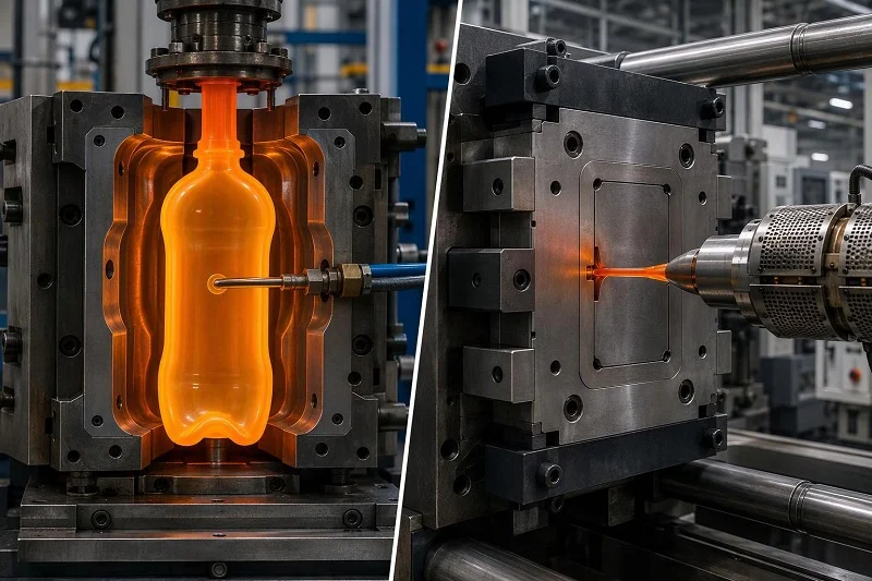
The cost comparison is not a single break-even figure but two curves with different shapes. Printing’s per-part cost stays comparatively flat; molding’s falls steeply as tooling amortises. Where they cross moves with the part.
Why Printed Unit Cost Stays Relatively Flat
Machine time, material and post-processing labour dominate printed cost, and each part consumes a similar share of all three regardless of order size. Published ranges put printed parts at roughly $5 to $200+ each depending on material, size and process. Packing a build improves efficiency, but mainly for powder-bed processes such as SLS and MJF; other processes gain far less from nesting. The practical consequence is that printing is almost always the cheaper total-cost route for very small quantities — commonly cited as roughly 1–100 parts — because there is no tooling to amortise.
Why Molded Unit Cost Falls With Volume
Tooling, not the per-part molding step, is the largest cost driver in a molding project. Amortising an aluminium mold costing roughly €3,000–€8,000 over a 100-part run works out to €30–€80 of tooling cost per part; amortising a full production steel mold at €15,000–€80,000+ over the same run works out to €150–€800 per part. That gap closes fast as volume rises, which is why matching tooling tier to real quantity matters more than defaulting to the longest-lasting option. Multi-cavity tools and short cycle times then compound the advantage, and for programs measured in tens or hundreds of thousands of units per year, molding delivers cost efficiency at scale that printing cannot match.
Finding Your Crossover
Published crossover points differ widely because they describe different parts. One commonly cited band places the break-even between 500 and 2,000 units for typical geometries and materials. A mass-customisation study using an energy-per-part metric found a crossover of 50 to 300 representative parts depending on mold plate material — and explicitly noted that the figure is specific to that part and expected to vary with geometry. A resin-printer manufacturer’s own race to 1,000 parts reported a break-even at 13,050 parts for its particular latch component. These are not contradictions; they are different parts, different tooling and different measures.
The practical method is to compare total project cost — tooling plus parts plus finishing plus likely engineering changes — at your realistic volume, not unit price alone. Treat any published break-even number as a starting hypothesis to be tested against your geometry, material and cavitation.
Design Freedom And Part Geometry
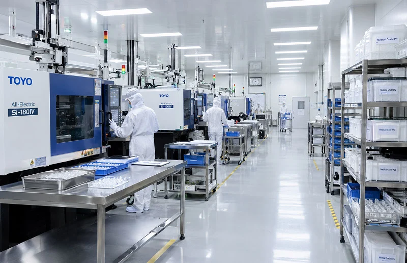
Geometry is where the two processes diverge most sharply, and where design decisions made early become expensive to reverse.
Undercuts, Internal Channels And Lattices
Printing builds undercuts, internal channels, lattice structures and enclosed geometries without draft or split lines. Molding handles undercuts through side actions, lifters or sacrificial cores, each of which adds tool cost and maintenance, and some internal geometries are effectively impossible in a rigid mold. Where a part’s function depends on conformal cooling channels or internal lattice, printing is not merely convenient — it is the only route.
Draft, Wall Uniformity And Shrinkage
Molding imposes design-time obligations. Draft angles — typically 1° to 3° — are needed to release the part; insufficient draft causes sticking, drag marks and surface scuffing during ejection, and excessive ejection force can deform features or leave pin marks. Wall thickness must be uniform to avoid sink marks and warping, and shrinkage behaviour must be compensated in the tool. These are not defects of molding but terms of using it, and they must be settled before the mold is cut.
Printing removes draft entirely but substitutes its own constraints: properties vary with build orientation, support marks affect surfaces, and thin or unsupported features may not resolve. The constraint moves from the tool to the build setup.
Designing For Additive Versus Designing For Molding
Printing an existing molded-part design is direct part conversion — useful for legacy parts or quick fabrication needs, but it captures little of printing’s benefit. The larger gains come from re-architecting: consolidating assemblies into single parts, replacing solid sections with lattice infill, and routing channels that a mold could never form. That redesign carries its own cost in engineering time, testing and certification, and it should be scoped deliberately rather than assumed.
Materials, Tolerance And সারফেস সমাপ্ত
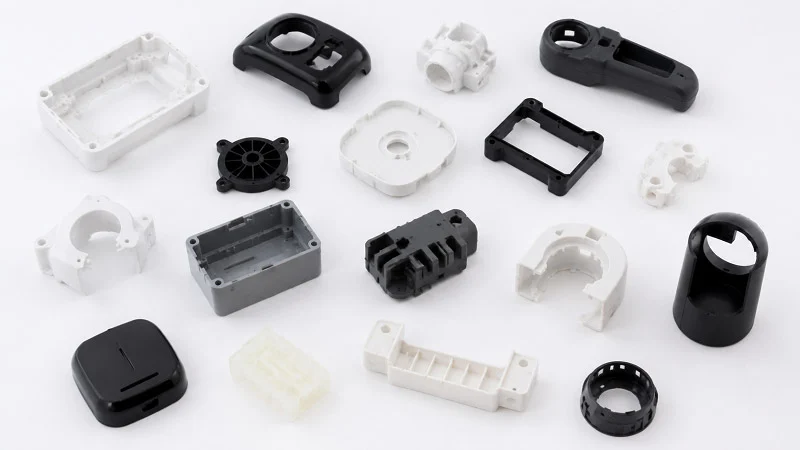
Material and quality requirements frequently override cost. A part that cannot be made in the right polymer, or held to the right tolerance, is not a candidate for the cheaper process.
Material Range And Production-Grade Resins
Molding draws on the full range of production thermoplastics, including filled and engineering grades, with properties established for the application. Material selection directly influences part strength, shrinkage, cosmetic finish, cycle time and long-term dimensional stability, and the right choice begins with functional requirements: mechanical load, temperature exposure, chemical resistance, cosmetic expectations and regulatory considerations.
Printing offers a narrower, process-specific set. Vat photopolymerisation relies on photopolymer resins that may exhibit limited mechanical strength compared with thermoplastics or metals; powder-bed systems work in nylon and similar polymers; filament systems cover engineering filaments. Where a medical-grade or production-grade material is required, confirm it for the specific material and process rather than assuming equivalence — a printed prototype in a stand-in resin does not establish that the production polymer will perform.
সহনশীলতা এবং পৃষ্ঠতল ফিনিশ
Published as-printed tolerances vary by process. FDM is the coarsest at roughly ±0.5% with a floor (tighter on industrial systems), with visible layer stepping. SLA and PolyJet give the finest as-printed surfaces, near injection-molded quality. SLS and MJF sit around ±0.3% with a floor and produce the characteristic grainy matte nylon finish, MJF typically slightly smoother than SLS. These figures assume well-calibrated machines and as-printed parts; warping, support-removal marks, orientation and post-processing all shift the result.
Molding’s advantage is repeatability: finish is taken from the tool surface and reproduced across the run. Where tolerances tighter than roughly ±0.05 mm are needed, secondary machining is typically required in either route, and cosmetic-critical surfaces may need polishing or texturing regardless of process.
Applications: 3D Printing vs Injection Molding
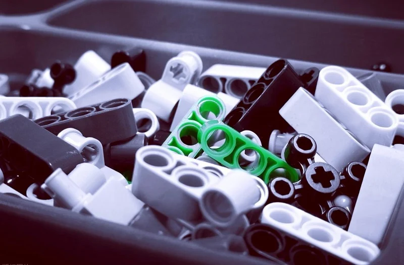
The criteria translate into recognisable application patterns across the industries NOBLE serves — automotive, aerospace, medical devices, robotics, automation, industrial and communication equipment, new energy and consumer products.
Where 3d Printing Wins
Printing fits fast iteration during development, complex or consolidated geometry, customised or patient-matched devices, low-volume and bridge production, and jigs and fixtures. The FDA describes 3D printing as enabling devices matched to a patient’s anatomy and devices with very complex internal structures, and lists orthopedic and cranial implants, surgical guides, dental restorations and external prosthetics among printed medical devices. The same logic — geometry freedom without tooling — applies to brackets, housings and fixtures wherever complexity would make a mold expensive.
Where Injection Molding Wins
Molding fits stable designs at volume, parts needing production thermoplastics and a consistent cosmetic finish, and programs where tooling cost amortises comfortably. The caveat is sequencing: the design must be frozen before the tool is cut. Where lifecycle stability and forecast demand are strong, molding provides predictable long-term economics; where the design may still move, it locks in cost prematurely.
Using Both In One Program
The common sequence is print for form, fit and function, then mold for production. A printed prototype can confirm fit, ergonomics and rough function, and it reduces the number of costly mold revisions. It does not confirm molded material properties, shrinkage behaviour, weld-line strength, tool feasibility or cycle economics — those require trial shots and qualification. Rapid tooling with printed inserts is a genuine bridge option, but with a limited cycle life; it is not a substitute for production steel.
Choosing NOBLE To Support Your Plastic Project
The decision this article walks through — matching process to part, volume and quality requirement — is the same decision a manufacturing partner has to help you execute. NOBLE is a Sino-British joint venture and an excellent Chinese contract manufacturer, recognised by the government as a National High-tech Enterprise. Our service capability and professional machining expertise help clients complete prototyping and volume production efficiently, carrying a project from design through assembly under one quality system rather than handing it between vendors.
We are certified to ISO 9001:2015 and ISO 13485:2016. We provide a full range of services from design to assembly — not production alone. For a plastic project, that means the process comparison above can be resolved against your actual geometry, material and quantity: printing where the design is still moving or the volume is low, molding where the design is stable and the tooling amortises, and a clear handover between the two when a program needs both. Our rapid prototyping and manufacturing capabilities cover a range of metal and plastic materials to stated specifications, supported by in-house inspection equipment and quality control.
If you are weighing 3D printing vs injection molding for a specific part, the useful next step is a quote based on that part, its volume and its quality requirement.
FAQs about 3D Printing vs Injection Molding
3D প্রিন্টিং কি ইনজেকশন ছাঁচনির্মাণ প্রতিস্থাপন করতে পারে?
For some parts, yes — particularly low volumes, complex geometry and customised devices. For production volumes in engineering thermoplastics with consistent cosmetic finish, molding remains the cost-efficient route once tooling amortises. The two are better treated as complementary stages than as substitutes.
How do I estimate the volume at which molding becomes cheaper?
Compare total project cost — tooling plus parts plus finishing plus likely engineering changes — at your realistic volume. Published crossovers range from roughly 50–300 units in one energy-based study to 500–2,000 units in general guidance and over 13,000 in a specific component case, because part size, material, cavitation and tool cost all move the point.
Can a printed prototype be used to approve a mold?
It can confirm fit, ergonomics and rough function, and it reduces costly mold revisions. It does not confirm molded material properties, shrinkage, weld-line strength, tool feasibility or cycle economics. Trial shots and qualification remain necessary before production approval.
Can the same design be used for both processes?
Often only with modification. A molded design carries draft, uniform walls and shrinkage compensation that printing does not need; a printed design may include lattices or internal channels a rigid mold cannot form. Printing an existing molded design is possible, but it captures little of printing’s design freedom.
How does material choice differ between the two?
Molding covers the full range of production thermoplastics, including filled and engineering grades. Printing offers a narrower set of process-specific materials — photopolymers, nylon powders, engineering filaments. Start from functional requirements and confirm medical-grade or production-grade suitability for the specific material and process.
What tolerance and finish should I expect from each?
As-printed tolerance varies by process: FDM is coarsest at roughly ±0.5% with a floor, SLA and PolyJet are finest, SLS and MJF sit around ±0.3% with a floor and a grainy matte finish. Molding is repeatable from the tool surface. Tolerances tighter than about ±0.05 mm typically require secondary machining in either route.
Verdict: matching the process to the part
Apply the rule directly. Choose 3D printing when the design is still moving, the geometry is complex or consolidated, or the volume is low enough that tooling cannot amortise. Choose injection molding when the design is stable, production-grade material and repeatable finish matter, and volume justifies the tool. Where a program needs both, print for validation and mold for production, and treat rapid tooling as a bridge rather than a destination.
The crossover is part-specific. The practical next step is a quote based on your actual part, volume and quality requirement — which is exactly what NOBLE can provide, from prototype through production.