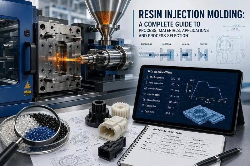
Resin injection molding sits at the centre of most plastic part programs, yet the phrase itself is one of the least precise in manufacturing. Suppliers use it to mean different processes, datasheets report properties under conditions that are rarely stated in a quotation, and the choice between molding and a competing process often turns on numbers that appear nowhere in the unit price. This guide is written for the engineers, product developers and sourcing teams who have to make that call: whether resin injection molding is the right route for a given part, how to specify it, and where it stops being economic.
The guide works through the subject in the order a program usually meets it. It defines the process and separates it from the similarly named processes it is often confused with, walks the molding cycle from pellet to ejected part, compares the main resin families and explains how to read the data that distinguishes them, sets out the design rules that prevent expensive defects, surveys typical applications, and compares resin injection molding against machining, 3D printing, compression molding, thermoforming and casting. It closes with volume economics, the support NOBLE offers, and answers to the questions that recur in quotation discussions.
Material data, test standards and process guidance change. Treat the figures here as orientation for specification work and confirm final values against the current grade datasheet and the applicable standard edition before a tool is cut.
What Is Resin Injection Molding?
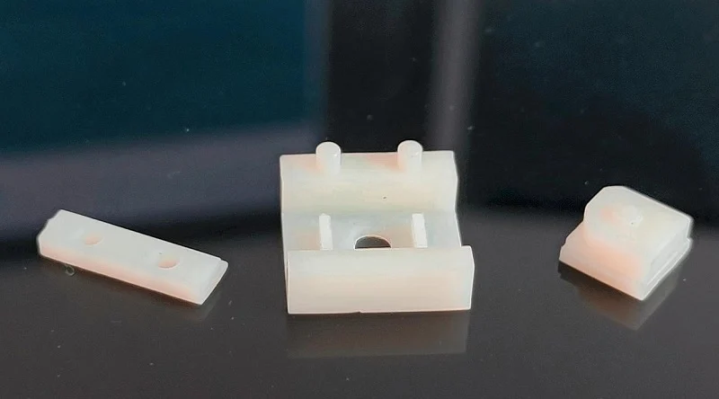
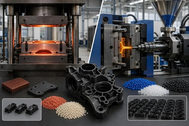
Resin injection molding is the thermoplastic injection molding process: pelletized polymer is melted in a heated barrel, forced under pressure into a closed, precision-machined metal mold, cooled until it is rigid, and ejected as a finished part. The word “resin” is used loosely across the industry, so when a supplier quotes “resin molding,” confirm which chemistry and which process the quote actually covers.
Resin Injection Molding vs. Resin Transfer Molding
Resin transfer molding is a liquid composite molding process, not a thermoplastic one. Dry fiber reinforcement, or a shaped fiber preform, is packed into a mold cavity; the mold is closed and resin is injected under pressure to impregnate the preform; the mold is then heated so the resin polymerizes into a rigid plastic. The reaction is thermally activated by the mold wall and the preform, and it is typically much slower than in structural reaction injection molding (SRIM), which allows a longer fill time at lower injection pressure.
The practical differences follow from that structure. Resin transfer molding produces fiber-reinforced composite parts — chairs, automotive components and aircraft structures are cited examples — and its advantages include low capital investment, good surface quality, tooling flexibility, large and complex shapes, ribs, cores and inserts, and a wide range of reinforcements. Resin injection molding starts from pre-compounded thermoplastic pellets, with no dry preform and no impregnation stage, and is built for high volumes of the same part. If your part is a short-fiber or unfilled thermoplastic component, resin transfer molding is the wrong process; if it is a continuous-fiber composite, resin injection molding is.
Thermoplastics and Thermosets in Resin Injection Molding
The thermoplastic–thermoset split governs everything downstream, from cycle design to whether scrap can be reground. Thermoplastics have linear or branched molecules with no chemical bonds between them; they soften and flow when heated and can be re-softened, because the change is a physical phase change. Thermosets begin with a similar chain structure but cross-link during processing, forming a three-dimensional network that makes the material infusible and insoluble — it cannot be re-softened and reprocessed by heat without degrading some linkages.
The general property trade-offs follow the same line. Thermoplastics offer higher impact strength, easier processing and better adaptability to complex designs. Thermosets offer greater mechanical strength, greater dimensional stability and better heat and moisture resistance. Most resin injection molding is thermoplastic, and the process described in this guide is the thermoplastic cycle; thermoset molding runs on different equipment and different cycles.
The Resin Injection Molding Process, Step by Step
The cycle runs from pellet to ejected part in a fixed sequence, and each stage controls something specific about the result. Knowing which stage does what is what lets you read a process sheet or a defect report rather than merely file it.
Material Feed, Drying and Plastication
Pelletized raw material is fed through a hopper into a heated barrel fitted with a reciprocating screw. The screw delivers the material forward, through a check valve, where it collects at the front of the screw into a volume known as a shot — the amount of resin required to fill the sprue, runner and cavities of the mold.
Drying comes before that, because many engineering resins are hygroscopic and absorb moisture from the air. Moisture in the melt turns to vapor during injection and shows up as splay, silver streaking or weakened weld lines. Dryer type, temperature and residence time depend on the specific grade, so take them from the resin supplier’s processing recommendations rather than from a generic rule.
Clamping, Injection, Cooling and Ejection
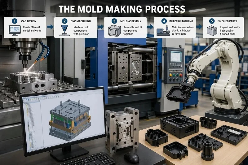
The injection molding cycle is short, typically between 2 seconds and 2 minutes, and has four stages. Clamping: the two mold halves are closed securely by a hydraulically powered clamping unit that exerts sufficient force to keep the mold closed while material is injected. Injection: with the mold closed, the polymer shot is forced into the cavity at high pressure and velocity. Cooling: once the cavity is filled, a holding pressure is applied so more polymer can enter and compensate for shrinkage as the part cools; meanwhile the screw turns, feeds the next shot forward and retracts as that shot is prepared. Ejection: when the part has cooled sufficiently, the mold opens, the part is ejected, and the cycle restarts.
Cooling usually dominates cycle time, which is why wall thickness and cooling layout drive the economics of a part more than the injection stage does.
What the Mold Contributes
Molds are created from metal, usually steel or aluminum, and precision-machined to form the features of the desired part. The mold has two primary components, the injection mold (A plate) and the ejector mold (B plate). Plastic resin enters through a sprue, or gate, and flows into the cavity via channels, or runners, machined into the faces of the two plates.
Gate location decides where the melt enters and therefore where weld lines form and how packing pressure distributes. Cooling layout sets how fast heat leaves the part, which governs both cycle time and warpage. Ejection design determines whether the part releases cleanly or is marked and distorted. These are tooling decisions, and they are why the mold is the long-lead item in any resin injection molding program: they are cheap to change on a screen and expensive to change in steel.
Resin Injection Molding Materials: How the Common Families Compare
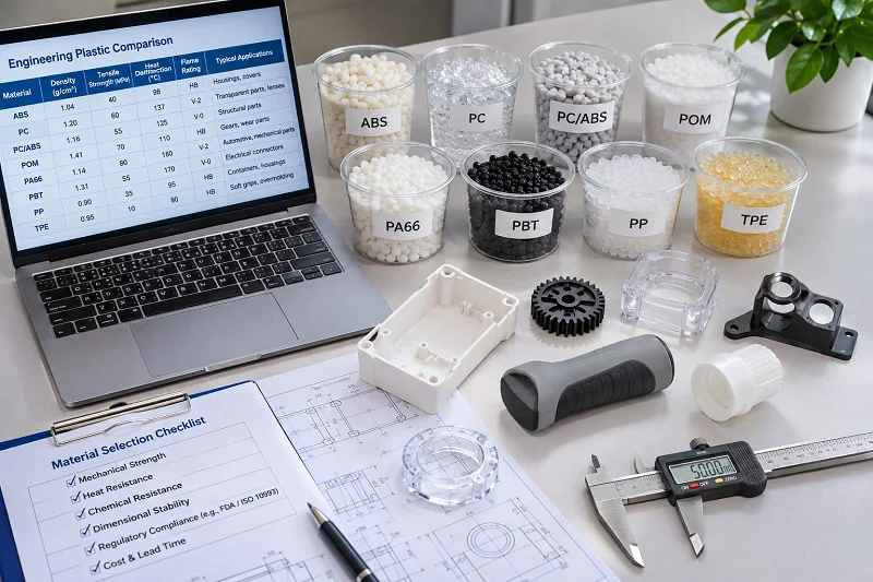
Material selection is where most cost and performance is decided, and it is usually argued at the wrong level. Families set the rough envelope; grades and fillers set the actual properties. The dimensions that drive selection are strength and stiffness, heat deflection, chemical resistance, impact, dimensional stability and cost, and each has to be read at grade level.
Standard, Engineering and High-Performance Resins
Four families cover most molding work. Standard resins — PP, PE-HD, PE-LD, PS, ABS, SAN and ASA — are the most widely used polymers in injection molding, chosen for cost-sensitive parts, containers and simple housings. Engineering resins — PA6, PA66, PA12, POM, PBT, PC, PC/ABS and PET — bring high mechanical and thermal resistance to functional parts such as housings, gears and clips. High-performance resins — PEEK, PPS, PEI, LCP and PPA — serve critical applications in aerospace and medical work where thermal, chemical or mechanical demands justify the step up. Elastomers — TPE, TPU, TPV and SEBS — provide flexibility and impact resistance for grips, seals and soft-touch features.
Each tier buys performance, and the cost step-ups concentrate where the resin must hold properties at temperature or under chemical attack.
Reading a Resin Datasheet Correctly
Datasheets are only comparable when they report the same property, by the same standard, under the same conditioning. The standard table covers density (ISO 1183), melt flow index (ISO 1133), tensile strength (ISO 527), flexural modulus (ISO 178), Charpy impact (ISO 179), heat deflection temperature (ISO 75), Vicat softening point (ISO 306), molding shrinkage (ISO 294-4) and flammability (UL 94).
Conditioning is the trap. A 30% glass-fiber polyamide datasheet can list tensile stress at break of 185 MPa dry and 115 MPa conditioned, with tensile modulus falling from 9,800 to 6,000 MPa — the same grade, two very different numbers. Compare grades at the same conditioning state, and note that tensile results also depend on specimen geometry, test speed and extensometer configuration, so a value without its standard and condition is not a specification.
Glass-Fiber Reinforcement and Property Trade-Offs
A 30% glass-fiber polyamide shows what a filler does to the comparison. Stiffness and strength rise sharply, and heat deflection rises with them. But strain at break falls to a few percent, so the material is far less forgiving of impact and of features that concentrate stress.
Shrinkage also becomes directional. One 30% glass-fiber PA66 grade lists molding shrinkage of 0.5–0.9% in the flow direction against 0.8–1.1% across flow, and another lists 0.20% flow against 0.60% across flow. That difference is a warpage mechanism, not a rounding error, and it has to be designed around. Moisture sensitivity compounds the effect: conditioned properties can be substantially lower than dry ones. “Nylon is strong” is a family-level statement; a grade-level specification names the grade, the filler content, the conditioning state and the test standard.
Heat Deflection Temperature: What the Number Does and Does Not Mean
Heat deflection temperature is measured under a defined bending load — 1.8 MPa (ISO 75 Method A) or 0.45 MPa (Method B) — at a uniform heating rate, and the reported value is the temperature at a specified deflection. The load matters enormously: measurements cited for polypropylene show HDT rising from 57 °C under Method A to 99 °C under Method B for the same material. A 30% glass-fiber PA66 grade likewise lists 210 °C at 1.8 MPa and 220 °C at 0.45 MPa.
HDT is a comparative value for ranking and quality control. It does not tell you the maximum operating temperature of the finished part, and it should never be used as one.
Designing Parts for Resin Injection Molding
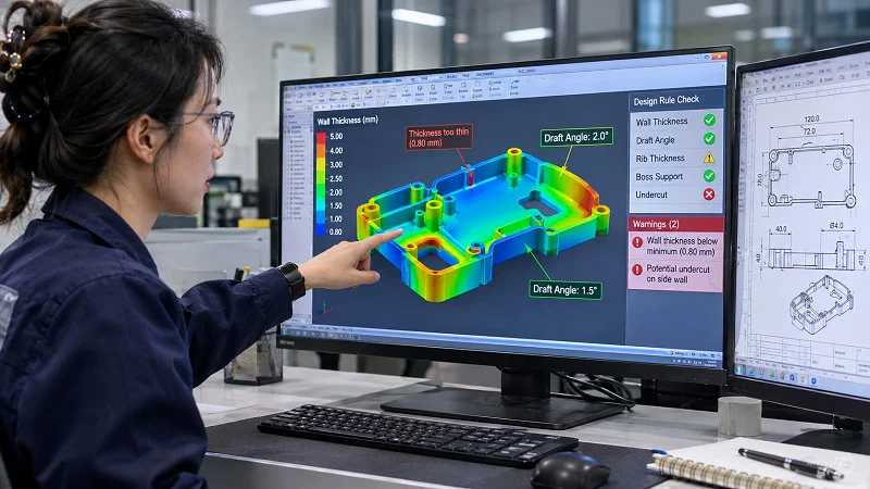
Design decisions are cheap before the tool is cut and expensive after. The rules below are pre-tooling checks: each one addresses a defect that is far easier to prevent in CAD than to correct in steel.
Wall Thickness, Ribs and Shrinkage
A local section thicker than roughly 60% of the nominal wall cools last. The surface freezes first, the interior keeps shrinking, and the pull draws the opposite face inward as a sink mark. The standard fix is to core the thick section out and replace it with ribs.
Rib geometry is where the rule becomes usable. Rib thickness at the base should be 0.5–0.6 × wall thickness, tightened to 0.4–0.5 × on textured or cosmetic faces; rib height should stay at or below 3 × wall; rib spacing centre-to-centre at least 2 × wall, so heat does not get trapped between ribs; and the rib base fillet at 0.25–0.5 × wall. Connect bosses to walls with a rib or gusset rather than a thick blend. Shrinkage compounds all of this: filled grades shrink differently in flow and cross-flow directions, and that anisotropy is a primary warpage risk.
Draft, Radii, Gates and Ejection
Draft on vertical walls lets the part release without scuffing; rib draft of 0.5–1.5° per side is a common starting point. Internal corner radii should be at least 0.5 × wall, because sharp internal corners are the leading stress riser, and external radii should be the internal radius plus one wall thickness so the wall stays uniform through the corner. Holes should sit at least two hole diameters from an edge or another hole to avoid weak, hard-to-fill webs.
Gate location decides where weld lines land and whether they fall on a cosmetic or structural surface. Ejection features should be placed where they will not mark a visible face or distort a thin wall. Exact values depend on material, texture and draw depth, so confirm them with the moldmaker rather than applying a table blindly.
Common Defects and Their Design Causes
Most recurring defects trace back to a small set of design causes. Sink marks come from thick walls, heavy bosses and thick ribs; core out the mass and use ribs. Warpage comes from uneven wall thickness, cooling imbalance and high shrinkage; use consistent walls and gradual transitions. Voids form in thick sections that cool unevenly. Flash follows poor shutoff design or a difficult parting line. Short shots reflect thin walls, long flow paths or poor gate location. Jetting appears when resin enters too quickly into open space, and is corrected by gate location or geometry.
Some flaws are inherent to the process and can only be managed, not eliminated. The design-fixable ones should be closed out before tooling; a design review at that stage is the cheapest defect correction available.
Applications of Resin Injection Molding

Resin injection molding is used to make wire spools, packaging, bottle caps, automotive parts and components, gaming consoles, pocket combs, musical instruments, chairs and small tables, storage containers, mechanical parts and many other plastic products. That breadth is real, but it is not a reason to mold anything. What actually drives the choice differs by sector: volume and cycle speed in consumer goods, heat and chemical resistance in automotive and industrial work, dimensional stability and documentation in medical and electronics.
Consumer Products and Packaging
Caps and closures, containers, housings, combs, small furniture components and similar goods are the classic high-volume territory for resin injection molding. Here the economics are dominated by cycle speed, cavity count and tool life rather than by exotic material performance, so commodity resins and multi-cavity tools usually carry the decision.
Automotive and Industrial Components
Under-hood and interior parts, brackets, housings, mechanical components and fluid-handling parts are typical automotive and industrial uses. In these positions engineering and high-performance resins earn their cost through heat and chemical resistance, and dimensional repeatability across long runs matters as much as the raw property values.
Medical, Electronics and Precision Parts
Device housings, fluid-path components, connectors and precision parts rely on resin injection molding where dimensional stability, cleanability and material documentation matter. Medical work in particular brings quality-system requirements into supplier selection, so the certification and inspection scope of the molder becomes part of the specification.
Resin Injection Molding Compared with Other Manufacturing Processes
Resin injection molding rarely wins or loses on unit price alone. The honest comparison runs on tolerance, surface finish, volume, material range and total delivered cost — and secondary operations such as machining, finishing or hardware insertion often decide the real winner.
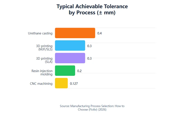
Typical achievable tolerances by process, as published in a process-selection guide. Ranges are industry approximations that vary with part complexity, material and supplier; injection molding values are part-dependent. Compare processes on total delivered cost, not tolerance alone.
Resin Injection Molding vs. CNC Machining
CNC machining typically holds ±0.025–0.127 mm with as-machined finishes of 0.8–3.2 μm Ra, while resin injection molding typically holds ±0.05–0.2 mm part-dependent at 0.8–1.6 μm Ra as-molded. Machining avoids tooling and suits low volume or tight tolerances; molding wins once the tool amortizes.
Resin Injection Molding vs. 3D Printing
SLA printing typically holds ±0.1–0.3 mm at 0.8–3.2 μm Ra, and MJF/SLS ±0.2–0.3 mm at 6.3–12.5 μm Ra. Printing carries no mold cost and suits prototypes and low volumes, but layer artifacts and anisotropic properties mean printed parts cannot match molded material performance — so printing bridges to resin injection molding rather than replacing it.
Resin Injection Molding vs. Compression Molding, Thermoforming and Casting
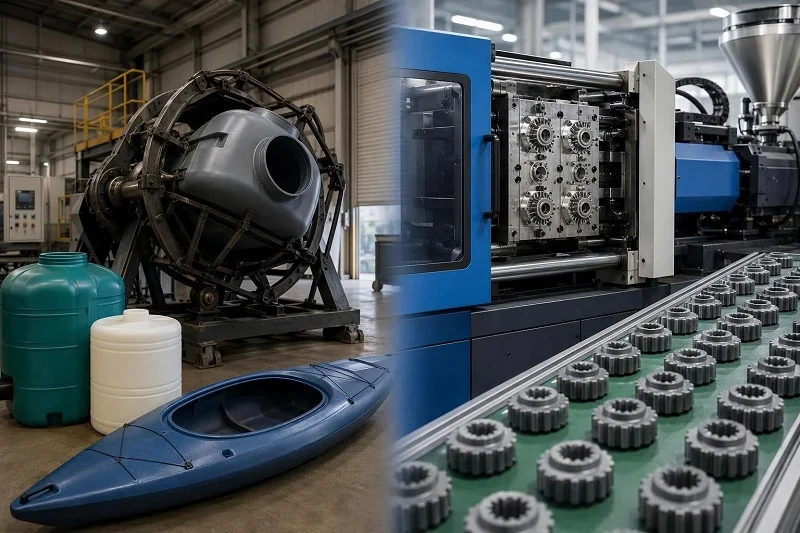
Compression molding suits simpler, flatter geometries and thermoset or composite compounds, with inherent parting-line flash; thermoforming serves large, shallow shells from sheet; urethane casting gives ±0.2–0.4 mm parts from soft molds limited to roughly 25–50 shots, making it a bridge rather than a production route. Each serves part types resin injection molding handles poorly or uneconomically.
A Process Selection Framework
Fix material and tolerance first, since both eliminate options immediately. Then estimate annual volume and part life, add tooling, finishing and secondary operations to reach total delivered cost, and check the shortlist against the tolerance and finish table above. The sequence matters: choosing a process before the requirements are fixed locks in constraints that compound later.
Volume Economics: Prototypes, Bridge Tooling and Mass Production
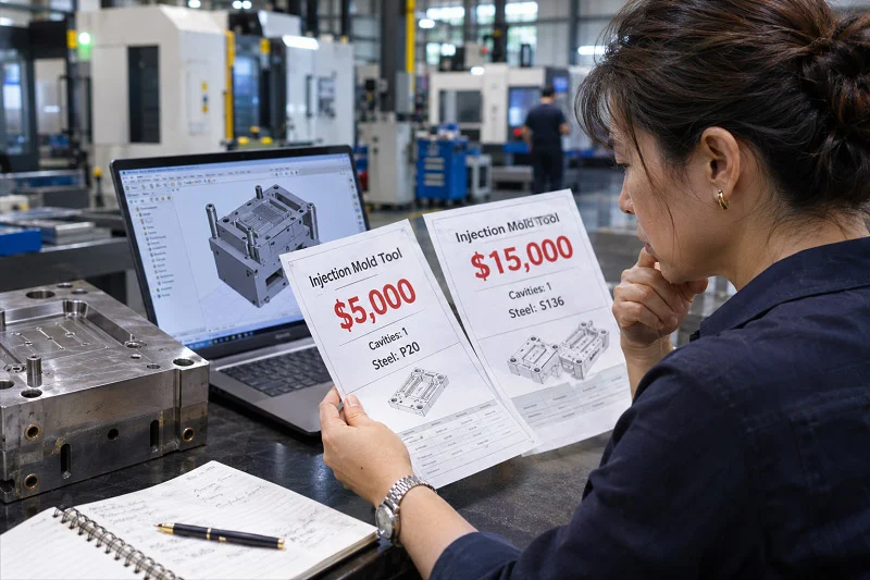
Whether resin injection molding makes sense is a quantity question before it is a technology question. The mold is a one-time engineering investment amortized across the run, so per-part cost falls steeply at low volumes and flattens once the tool is paid off. A simple single-cavity mold typically runs $10,000–$50,000, and a complex multi-cavity or family mold can reach $100,000 or more.
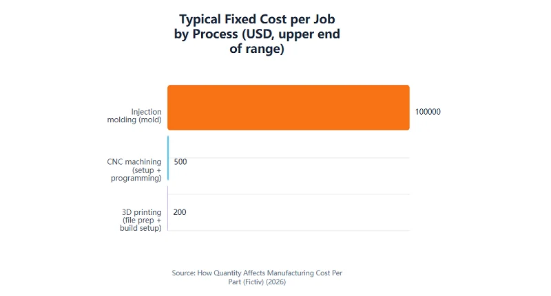
Typical fixed cost per job by process, as published in a cost-per-quantity analysis. Injection molding’s mold cost is a one-time engineering investment amortized across the run, which is why its per-part cost falls steeply at low volumes and flattens once the tool is paid off. Figures are industry approximations, not quotations.
When Resin Injection Molding Becomes Economic
Resin injection molding is generally not economic below roughly 1,000–5,000 units for most plastic parts, and that threshold rises for complex molds. Part size, cavity count, material and finishing shift it further. Treat the range as a planning heuristic, not a guarantee, and let total delivered cost including finishing drive the decision rather than the quoted unit price.
Prototype and Low-Volume Pathways
Most programs reach production tooling in stages, and each stage should retire a specific design risk before the next investment. Machining or 3D printing covers functional prototypes and fit checks, though printed parts cannot reproduce molded material performance. Bridge tooling — often aluminum — produces real molded samples in the intended resin, exposing gate effects, shrinkage, weld lines and ejection behavior that prototypes miss. Cast urethane suits pilot builds where mold life of a few dozen shots is enough. Production tooling follows once geometry, material and tolerances are frozen.
Choosing NOBLE to Support Your Resin Injection Molding Project

NOBLE is a leading Chinese contract manufacturer supporting customers from prototype through volume production. Our service capability and machining expertise help you move efficiently from prototype to batch production, backed by ISO 9001:2015 and ISO 13485:2016 certification and a full scope that runs from design to assembly — not production alone.
One Partner from Design to Assembly
Keeping design support, prototyping, machining and manufacturing, assembly and inspection under one roof removes handoffs between vendors. Tolerances, material records and documentation stay consistent across the program instead of being renegotiated at each transfer, which is where most schedule and quality surprises originate.
Quality Systems Built for Regulated Work
ISO 9001:2015 signals a general quality management system; ISO 13485:2016 sets requirements specific to the medical device industry, and third-party certification can demonstrate to regulators that those requirements are met. Both are quality-system credentials, not product certifications, and our inspection equipment supports dimensional verification against your drawing.
Getting a Quote and Starting the Conversation
If you have an active resin injection molding project, prepare drawings or CAD, material and finish requirements, target volumes and the tolerance callouts that actually matter functionally. NOBLE can review that information and clarify the next quotation steps, with a professional quote typically returned within 24 hours of a complete RFQ.
FAQs About Resin Injection Molding
These are the questions that come up most often once a team moves from reading about resin injection molding to specifying a part.
Is Resin Injection Molding the Same as Plastic Injection Molding?
In common usage, yes — both describe the same thermoplastic process of melting pellets and injecting them into a closed mold. The meaningful distinctions are against resin transfer molding and reaction injection molding, which use different chemistry and equipment.
Which Resin Should I Choose for My Part?
Define the service temperature, chemical exposure, impact and stiffness requirements first, then shortlist material families and compare specific grades on datasheet values reported at the same test standard and conditioning state.
Can Resin Injection Molding Produce Prototypes?
Rarely at production economics. A hardened steel mold is built to amortize across thousands of shots, so for a handful of parts the usual route is CNC machining or 3D printing for functional prototypes, then bridge tooling or cast urethane for pilot builds once the geometry is close to final.
What Tolerances Can Resin Injection Molding Hold?
Typical as-molded tolerance is around ±0.05–0.2 mm, and the achievable value depends on the part. Call out tight tolerances only where function requires them, since tighter callouts raise tooling cost and inspection burden.
How Long Does a Molding Cycle Take?
Typically 2 seconds to 2 minutes per cycle. Cooling usually dominates that time, and it scales with wall thickness and material, so a thin-walled cap and a thick housing run on very different clocks. Tooling lead time is a separate schedule item, not part of the cycle.
What Causes Sink Marks and Warpage?
Both trace back to uneven cooling and shrinkage. A section thicker than roughly 60% of the nominal wall cools last, shrinks after the surface freezes and pulls the face inward as a sink mark; uneven walls and unbalanced cooling produce warpage instead. Coring out thick sections and replacing them with ribs is the standard fix, applied before the tool is cut.