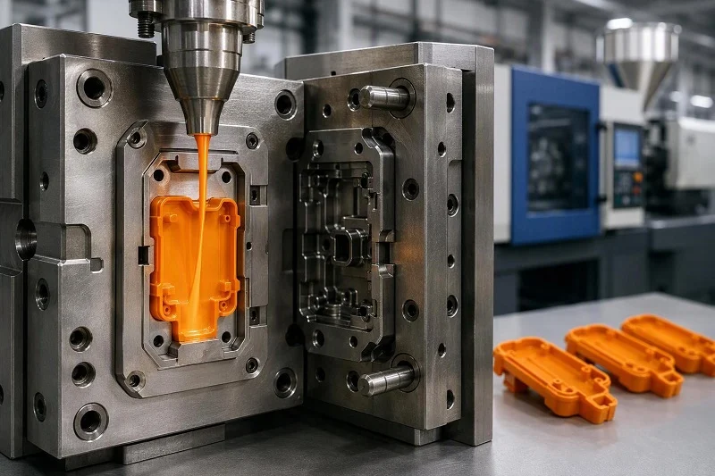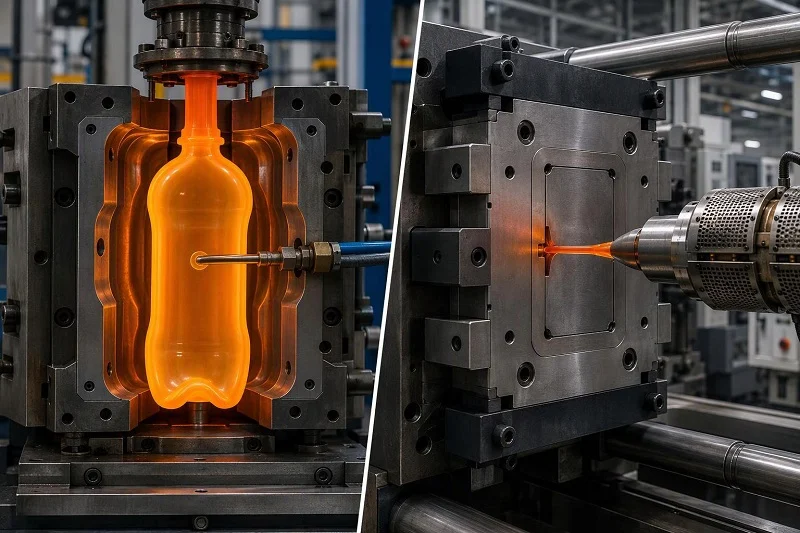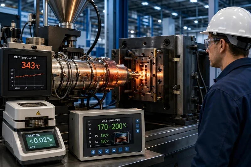
PEEK injection molding is defined by three numbers that sit far outside ordinary plastics practice: a 343 °C melting point, a dryness requirement below 0.02% moisture, and a mold held at 170–200 °C — hotter than the melt of most commodity resins. Every other decision in PEEK injection molding follows from those three. A press that cannot hold 400 °C, a dryer that cannot reach a −40 °C dew point, and a tool that cannot be heated evenly will each produce scrap from resin that costs many times more than ABS or polycarbonate.
This guide follows the chain from pellet to inspected part for engineers and product developers deciding whether to mold PEEK at all. It covers the process step by step and the reason behind each control, the parameters that actually move part quality, where molding wins and where it quietly costs more than machining, how to pick a grade from the failure the part must survive, and which applications justify the tooling. Figures come from published material datasheets and processing guides on standard PEEK grades rather than from a single test program, and they describe typical laboratory conditions, not guaranteed values for a specific part.
What PEEK Is and Why It Is Molded as Well as Machined
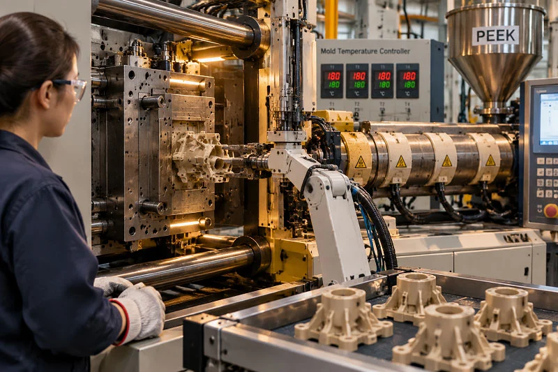
PEEK is a semi-crystalline polyether ether ketone. Published datasheets for standard unfilled grades list a melting temperature of 343 °C, a glass transition of 143 °C onset and 150 °C midpoint, and a relative thermal index for electrical use of 260 °C. Continuous allowable service temperature in air is commonly quoted at 250 °C over 20,000 hours, with a continuous service range of 250–260 °C. Those are typical figures from laboratory specimens; a molded part’s real properties depend on its geometry, the tool configuration and the processing conditions actually used, which is why the datasheets themselves say the data are for material comparison.
The same polymer arrives in two forms. Unfilled PEEK is supplied as granules for injection molding and extrusion, and the same chemistry is available as rod and plate for machining. Choosing between them is a volume-and-geometry decision, not a materials decision — the chemistry that resists steam sterilization and aggressive chemicals is identical. What changes is how much resin you buy, how much of it becomes chips, and whether the shape can be cut at all.
One distinction matters early. PEEK is often described as not hygroscopic, and that is true in the sense that it does not dissolve or swell with water the way nylon does. It still absorbs moisture: processing guidance notes that pellet form typically takes up about 0.5% w/w atmospheric moisture, and datasheets list water absorption at saturation of 0.45% at 23 °C. That absorbed fraction is roughly twenty-five times the 0.02% limit set before molding, which is why drying is not optional even for a polymer that resists hydrolysis in service.
The PEEK FormsprutningsprocessSteg för steg
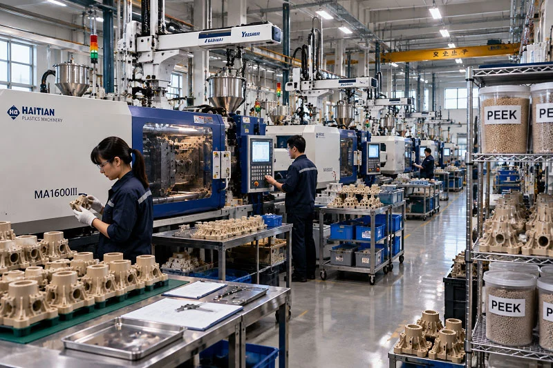
The sequence below follows established processing guidance for standard PEEK grades. Each step exists because of a specific failure it prevents.
1. Storage And Handling
PEEK ships sealed in polyethylene inside a heavy-duty box, and processing guidance recommends keeping it sealed through transport and storage, opening boxes only in a clean area and resealing leftovers. Sealed, dry, out of sunlight, the material can be stored for more than ten years. The reason is contamination rather than shelf life: at 380 °C, a few grains of another polymer or a speck of dust become black specks or a weak weld line, and the resin is too expensive to scrap for housekeeping.
2. Torkning
Pellets go into an air-circulating oven at 120–150 °C for 3–5 hours, spread in trays about 2.5 cm deep, until residual moisture falls below 0.02% (a −40 °C dew point). Either 150 °C for 3 hours or 120 °C for 5 hours is accepted as an equivalent route. Standard guidance is explicit that PEEK must not share an oven with other materials unless properly isolated. Moisture at melt temperature produces surface defects and loss of molecular weight, so the drying step protects both appearance and mechanical performance.
3. Feed Throat
The hopper is held below 100 °C — datasheets for unfilled grades specify under 100 °C, while extrusion guidance suggests pre-heating granulate in the 140–180 °C range for that process. The aim in molding is to keep pellets from bridging or partially melting before they reach the screw while limiting re-absorption of moisture on the way in.
4. Plasticizing
The barrel must reach 400 °C controllably, to within roughly ±2 °C, which rules out cast aluminum heaters in favor of high-temperature alloy or ceramic types. Screws of 18:1 to 24:1 L/D with a 2:1 to 3:1 compression ratio are typical, and a check ring at the screw tip is required to hold injection pressure. Residence time should be kept short; the melt can be held at 360 °C for up to an hour without appreciable degradation, but beyond that barrel temperatures should drop to 340 °C, and a delay longer than three hours calls for purging the barrel.
5. Injektion
Melt temperatures run roughly 355–395 °C depending on grade. For unfilled PEEK, a typical rear/middle/front/nozzle profile is 355 / 360–365 / 370 / 375 °C; a 30% glass-filled grade pushes that to 360 / 370–375 / 380 / 385 °C, and a 30% carbon-filled grade to 375 / 380–385 / 390 / 395 °C. The stable working range is generally given as 360–400 °C. Injection pressures rarely exceed about 14 MPa with holding pressures around 10 MPa for natural PEEK, though precision parts with long flow-to-thickness ratios can need more than 200 MPa.
6. Mögeltemperatur
The tool surface is held at 170–200 °C (processing guides often quote 175–205 °C; datasheets quote 170–200 °C for unfilled PEEK). This is the surface temperature, not the controller setpoint — with oil heating, flow-line losses of up to 40 °C are common, so setpoints of 260 °C are typical to achieve 170 °C at the steel. The reason is crystallinity: a cold tool quenches the surface into an amorphous state, producing non-uniform color, dark or transparent edges, and lower strength and chemical resistance. Standard guidance states that parts molded under recommended conditions should be nominally 30% crystalline.
7. Packing, Cooling And Ejection
Holding pressure compensates for shrinkage as the part cools against the hot tool. Cooling time scales with wall thickness; published cooling-time curves at a 180 °C tool temperature show that better ejection design can cut cooling time by about 15% for unfilled grades. Parts are ejected while still rigid enough to avoid distortion.
8. Glödgning
Where dimensional stability or stress relief matters, molded parts can be annealed. A typical program for a section up to 20 mm ramps to 150 °C at no more than 30 °C/h, holds 3 hours, ramps to 200 °C at the same rate, holds 4 hours, then cools at no more than 15 °C/h. Annealing also completes crystallization and stabilizes shrinkage.
9. Inspektion
Final checks confirm dimensions, appearance (dark edges and black specks are the classic PEEK defects) and, where specified, crystallinity by DSC. First-article approval that includes crystallinity data closes the loop on whether the tool actually ran hot enough.
Processing Parameters That Decide Part Quality
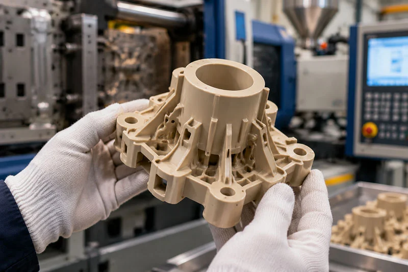
The parameters that decide whether a PEEK part meets its drawing are fewer than the full machine setting list suggests. They are drying, melt temperature, mold temperature, injection pressure and speed, gate and runner size, and shrinkage allowance. The table below contrasts three standard grades on the values that shift most between them, taken from their datasheets.
| Parameter | 450G (unfilled) | 450GL30 (30% glass) | 450CA30 (30% carbon) |
| Melt viscosity at 400 °C | 350 Pa·s | 550 Pa·s | 675 Pa·s |
| Molding shrinkage, flow direction | 0.90% | 0.30% | 0.10% |
| Molding shrinkage, across flow | 1.3% | 0.90% | 0.50% |
| Nozzle temperature (typical) | 375 ° C | 385 ° C | 395 ° C |
| Mold temperature (typical) | 170-200 ° C | 180-200 ° C | 180-210 ° C |
| Minimum gate | > 1 mm | > 2 mm | > 2 mm |
| Torkning | 120–150 °C, 3–5 h, <0.02% | Samma | Samma |
Molding shrinkage of three standard PEEK grades along and across the melt flow direction, measured on ISO 294-4 test specimens at grade-specific nozzle and tool conditions (unfilled: 375 °C nozzle, 190 °C tool; 30% glass: 385 °C nozzle, 190 °C tool; 30% carbon: 395 °C nozzle, 200 °C tool). Values are for material comparison only — actual shrinkage depends on part geometry, mould configuration and processing conditions.
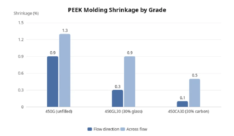
Three things follow from the table. First, filled grades are stiffer melts — 550 and 675 Pa·s against 350 Pa·s — so they need higher barrel setpoints and larger gates to fill the same wall. Second, shrinkage collapses in the flow direction as fiber content rises, but far less across flow, which is why the same part shrinks differently along and across the melt path. Third, the gate rule roughly doubles for compounds: the minimum is 1 mm for unfilled PEEK and 2 mm for compounds, or about two-thirds of wall thickness for thick parts, with sprue gates 1 to 1.5 times the molding thickness. Runners should exceed 3 mm at the die and nozzle and 3.5 mm in the manifold.
Injection pressure and screw speed are secondary adjustments once those are set. General-purpose screws are suitable and back pressure improves melt homogeneity, while typical guidance recommends peripheral screw speeds of 5–10 m/min for unfilled grades and no more than 6 m/min for reinforced ones, because high local shear overheats the melt. Back pressures of 2–8 MPa are usual, lower for filled grades to treat the fibers gently.
On shrinkage, use the datasheet numbers to compare grades, not to cut steel. Datasheets state plainly that shrinkage data are for material comparison and that actual values depend heavily on part geometry, mold configuration and processing conditions; standard practice adds that tools should always be cut on the metal-safe side. A first article measured on your own geometry is the only reliable correction.
Advantages of PEEK Injection Molding — and When Each One Holds
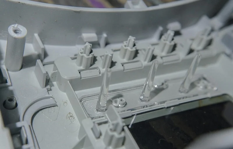
The advantages of molding PEEK are real, but each one is conditional, and stating the condition is what separates a useful claim from a sales line.
Net-Shape Complex Geometry
Molding produces bosses, ribs, clips and threads in one shot, where machining would require multiple setups and might not reach the feature at all. The condition: the tool must be correctly gated and vented. Troubleshooting guides attribute short moldings and weld lines to inadequate venting and gate design as often as to machine settings, so the geometry advantage is only as good as the tool design behind it.
High-Volume Economics
A molded part consumes grams of resin per shot; a machined part starts as a billet and leaves most of it as chips. The condition: tooling must be amortized. Below that volume, the tool cost dominates and machining is cheaper — the crossover is the subject of a later section.
Repeatable Properties At Temperature
Because the mold temperature drives crystallinity, a well-controlled hot tool delivers consistent strength, chemical resistance and dimensional behavior across a production run. The condition: the tool surface must actually reach the intended temperature. A tool that runs cold produces parts that look complete and then fail at loads a commodity plastic would survive.
Elimination Of Secondary Machining
Features that would otherwise be cut after molding come out of the tool, saving setups and avoiding the surface disruption machining causes. The condition: tolerance requirements must sit within molding capability. Typical tolerances run at approximately 0.05% under standard molding conditions — fine for many features, but not a substitute for machining where the drawing demands tighter.
Material Efficiency And Design Freedom
Molding allows wall thickness, ribbing and internal features that would be difficult or impossible to cut, and it avoids the blank waste that makes machined PEEK expensive. The condition: the part must be designed for molding, with uniform walls and adequate draft, which the design section covers.
None of these advantages should be claimed for a specific part without checking its geometry. A large, simple shape with a loose tolerance may see none of them.
Limitations and Hidden Costs
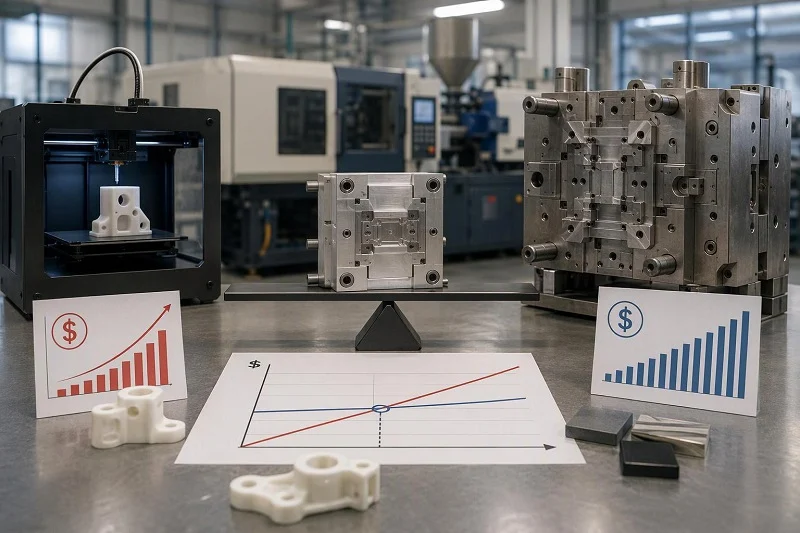
The costs that surprise first-time PEEK molders are rarely the resin price alone. They sit in the tool, the energy bill and the scrap rate.
The Hot Tool
Holding a mold at 170–200 °C requires oil heating, electrical cartridge heaters, or a combination. Electrical heating is economical and easy to service but prone to hot spotting, best suited to small components; oil heaters are harder to design but can extract heat, which matters for large shot sizes and deep cores. Insulation boards between mold and platen are strongly advised, and oil lines should be short and insulated because heat losses of up to 40 °C are common. All of this adds capital, heat-up time and energy to every cycle.
Cykeltid
A hot mold cools the part more slowly, and thick sections extend cooling further. Published cooling-time estimates as a function of wall thickness at 180 °C tool temperature rise steeply with thickness. PEEK parts are therefore not fast to mold, which raises the cost per part even when resin use is low.
A Narrow Processing Window
The melt is stable between roughly 360 and 400 °C, but outside that band the failure modes multiply: too cold and the melt freezes at the nozzle or short-shots; too hot or held too long and it degrades into brittle parts and dark streaks. With resin this expensive, every scrapped shot is a real loss, and the scrap rate is highest during startup and grade changes.
Regrind Limits
PEEK can be reworked, but standard guidance restricts regrind to a maximum of 30% w/w for unfilled polymer and 10% w/w for filled compounds, and warns that even low levels of extraneous material seriously affect molding quality at these temperatures. That caps how much runner scrap can be recovered, especially with filled grades.
Föroreningskänslighet
Dedicated scoops, trays and drying equipment are strongly recommended, and processing literature notes that black specks in natural grades usually trace to cross-contamination or insufficient purging. A shop running PEEK alongside other polymers needs segregation discipline or it will lose parts to contamination.
Hot Runner Trade-Offs
Hot runners save material and widen the processing window, but they carry higher initial capital cost, major contamination problems when purging, and higher overall maintenance than cold runners. The system must run consistently at 450 °C, with external heating and no internal flow restrictions, and nozzle tips should be generous rather than pin-gated.
Toleransgränser
Molding cannot hold the tightest tolerances without secondary operations. Where a drawing calls for better than standard molding capability, plan for machining after molding and price it in.
Cost figures for all of the above vary too widely by part, volume and shop to quote responsibly here. The right approach is to treat them as directional: a hot tool, slow cycles and capped regrind all push unit cost up, and the volume at which molding beats machining moves accordingly.
Choosing a PEEK Grade for a Failure Mode
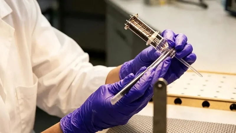
Grade selection is easier if you start from the failure the part must survive rather than from a property table. The three standard Victrex grades map onto three different failure modes.
Tensile modulus at 23 °C (ISO 527-1) and strain at break at 23 °C (ISO 527-2) for three Victrex PEEK grades, from supplier datasheets. Datasheet values describe laboratory specimens for material comparison; a moulded part’s properties depend on its geometry, tool configuration and processing conditions.
Unfilled Grade — for ductility and toughness
The datasheet gives 25% strain at break, a tensile modulus of 4,000 MPa, and no break on both Charpy and Izod unnotched impact tests at 23 °C. Unfilled PEEK offers the highest elongation and toughness in the family, which suits instrument and seal components where ductility and inertness are critical. Choose unfilled when the part must flex, absorb impact, or seal against a mating surface without cracking.
Glass-Filled Grade — for static stiffness and low thermal expansion
Thirty percent glass raises tensile modulus to 11,500 MPa and gives a heat deflection temperature of 328 °C at 1.8 MPa, with a flow-direction coefficient of linear thermal expansion of 18 ppm/K below the glass transition. The datasheet describes its applications as higher strength in a static system with a low coefficient of thermal expansion. Choose it when the part must hold shape under load at temperature and stay dimensionally stable — a structural bracket, a housing, a component that must not grow into a neighbor.
Carbon-Filled Grade — for wear and the highest modulus
Thirty percent carbon fiber gives a tensile modulus of 28,000 MPa, the lowest flow-direction shrinkage in the family at 0.10%, and the datasheet’s description of excellent wear resistance and low coefficient of friction in static or dynamic systems. Choose it when the part slides, rubs or carries load and stiffness matters more than elongation.
The trade-offs are consistent across the filled grades. They are more abrasive to tooling, which is why wear-protected screws and bimetallic barrels are recommended and why gate sizes double. They lose elongation — 3.0% for a 30% glass grade and 1.7% for a 30% carbon grade against 25% unfilled — so a part that must bend should not be filled. And they shrink anisotropically, with the across-flow figure several times the flow figure, which complicates tool correction. Keep every claim tied to the grade’s own datasheet; a number from one grade does not transfer to another.
Applications Where PEEK Injection Molding Fits

PEEK earns its cost in applications where temperature, chemistry or sterilization would defeat ordinary engineering plastics. Molding earns its place when those applications also need volume, complex geometry or repeatability.
Sjukvård
PEEK withstands repeated steam sterilization, and published medical-grade testing reports no significant loss of mechanical properties above 1,500 sterilization cycles at 134 °C, measured on plastic specimens without cleaning cycles. Surgical instruments, trial implants and dental components are typical. Biocompatibility is not automatic from the polymer: ASTM F2026-23 sets requirements for virgin PEEK in surgical implant applications and explicitly excludes filled, colored or reclaimed forms, and the FDA’s ISO 10993-1 guidance frames biological evaluation as a risk-management process. Molding suits this sector when instruments or single-use components are needed in volume with consistent geometry; machining suits patient-specific or low-volume implants.
Aerospace och Bil
Lightweight parts that must survive high under-hood or airframe temperatures benefit from PEEK’s continuous service capability around 250 °C and its strength retention at temperature — the 450G datasheet shows flexural stress of 85 MPa at 125 °C and 19 MPa at 175 °C. Molding fits brackets, bushings and housings where the geometry is complex and the volume justifies a tool; large or simple parts often stay machined.
Elektronik och halvledare
PEEK’s electrical properties hold over a wide temperature range, and its dimensional stability suits small precision components produced in high volume — the classic case for molding, where thousands of identical parts come off one tool.
Energy and Oil and Gas
Chemical resistance to acids, bases, hydrocarbons and solvents at elevated temperature, plus hydrolysis resistance in steam and seawater, make PEEK a candidate for seals, valve components and downhole parts. Molding suits repeatable small parts; large or one-off components are usually machined from stock shapes.
Industriell utrustning
Wear parts, bearings and bushings benefit from the carbon-filled grade’s low friction and wear resistance. Where these are consumables replaced in quantity, molding amortizes quickly.
In each case the logic is the same: the property justifies PEEK, and the volume or geometry justifies molding rather than machining.
När Maskin PEEK Instead of Molding It
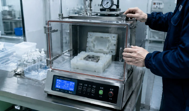
Machining remains the right answer for a large share of PEEK parts, and knowing when saves money.
Machine when volume is low. Below the point where tooling amortizes, the tool cost dominates and PEEK injection molding is the more expensive route. Prototypes, bridge tooling and one-off fixtures belong on a mill or lathe, where no tooling bill arrives and design changes cost only programming time.
Machine when geometry is large or simple. A big, blocky part with few features wastes little when cut from a billet, and a mold for it would be large, hot and expensive. The blank waste that makes machined PEEK costly is proportional to how much of the billet becomes the part; for a simple shape, most of it does.
Machine when tolerances exceed molding capability. Typical molding tolerances run about 0.05% under standard conditions. Where a drawing demands tighter, or features that molding cannot form, plan for machining — either the whole part or a secondary operation after molding.
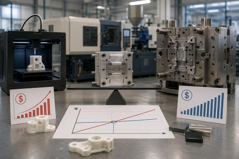
Mold when annual volume amortizes the tool. The calculation has four variables: tool cost, part size (which sets shot weight and cycle time), resin cost per shot, and the machining stock removal avoided. As volume rises, the tool cost spreads over more parts and the per-shot resin saving compounds. The crossover is specific to each part; the way to find it is to request a quote that separates tooling from part cost and compare it against a machining quote at the same annual volume.
Mold when geometry is complex and net-shape. Bosses, threads, clips and internal features come free from a well-designed tool and cost setups when machined.
Mold when repeatability across many parts matters. A single tool produces identical parts shot after shot; machining depends on setup consistency. For a production program, molding’s repeatability is itself a quality advantage.
The honest framing is a volume-versus-tooling-amortization calculation, not a rule of thumb. Any specific dollar figure would be invented; the variables are what matter.
Designing for PEEK: Verktyg and Part Rules That Prevent Scrap

Most PEEK scrap traces to a handful of design decisions made before steel is cut. The rules below exist because of the high melt and mold temperatures, not because PEEK is unusually difficult to design around in principle.
1. Uniform wall sections.
Typical guidance gives minimum wall thicknesses of about 1 mm for unfilled PEEK compounds and 1.5 mm for filled ones. Uniform walls cool evenly and shrink evenly; thick-to-thin transitions create sinks, voids and warpage that no machine setting can fully fix.
2. Generous, well-vented gates.
A minimum gate of 1 mm for unfilled and 2 mm for compounds is standard, or about two-thirds of wall thickness for thick parts, with sprue gates 1 to 1.5 times the molding thickness. Minimum sprue gates run about 4 mm with an input diameter 1.5 times the largest part thickness. Large gates keep the melt flowing and reduce sink marks and voids; adequate venting prevents short shots and burn marks.
3. Hot runners specified for 450 °C.
If a hot runner is used, it requires external heating with no internal flow restrictions, consistent operation at 450 °C, generous nozzle tips sited on the component surface, and very good individual temperature control to keep the tool balanced. Pin gating is not recommended.
4. Tool steels that hold hardness at temperature.
Cavity and core hardness of Rockwell 52–54 at PEEK processing temperatures is the usual target. Common choices are steel grades that retain about 54–58 HRC at temperature, including 1.2343 ESU, 1.2379, 1.2083 and 1.2316. Filled grades are abrasive, so wear resistance at the gates matters.
5. Allowance for anisotropic shrinkage.
Shrinkage differs along and across flow, and more so with fillers — 0.90% versus 1.3% for 450G, 0.10% versus 0.50% for 450CA30. Cut the tool metal-safe and correct from first-article measurements on the actual geometry rather than from datasheet shrinkage alone.
6. Process simulation before cutting steel.
Simulation should always come before cutting steel, to place gates for balanced flow, minimize knit lines and determine where venting is needed. On a tool built for 200 °C service, a steel change is expensive, so the simulation is cheap insurance.
Conclusion of PEEK Injection Molding

PEEK injection molding pays off when volume and geometry justify a hot tool and disciplined drying; below that threshold, machining remains the right answer. The process chain is fixed — sealed storage, drying to under 0.02% moisture, a 400 °C-capable plasticizing unit, a tool held at 170–200 °C, controlled packing and cooling, annealing where needed, and inspection that includes crystallinity. The parameters that decide quality are drying, melt temperature, mold temperature, gate and runner size, and shrinkage allowance, and they shift by grade: 350, 550 and 675 Pa·s melt viscosity and 0.90%, 0.30% and 0.10% flow-direction shrinkage for unfilled, glass-filled and carbon-filled PEEK.
Grade selection follows the failure mode: unfilled for ductility and toughness, glass-filled for static stiffness and low thermal expansion, carbon-filled for wear and the highest modulus. Applications follow the same logic — medical, aerospace, automotive, electronics, energy and industrial parts each justify PEEK for a specific property, and molding for a specific volume or geometry.
The next step is to define annual volume, tolerance and geometry, then request a quote that separates tooling from part cost. That comparison, against a machining quote at the same volume, is the only reliable way to decide which process the part should use.
Working With NOBLE on Your PEEK Injection Molding Project
Adeln custom PEEK injection molding services cover steel and aluminum tooling, single-cavity, multi-cavity and family molds, and presses from 50 to 500 tons, with part-to-part repeatability of ±0.1 mm and mold cavity tolerances of ±0.05 mm. PEEK is listed among the materials handled, and inspection is supported in-house with ZEISS CMM equipment. Those figures describe NOBLE’s general molding capability; they are not a PEEK-specific case history, and a PEEK program should still confirm the points above — barrel temperature capability, tool heating method, drying dew point and crystallinity inspection — against the specific press and tool that will run the part.
What to prepare before requesting a quote: the 3D model and drawing with tolerances called out, the annual and launch volumes, the service environment (temperature, chemicals, sterilization cycles), the grade or a statement of the failure mode the part must survive, and any regulatory standard the part must meet. With those in hand, a quote can separate tooling from part cost, which is the only way to compare molding against machining honestly.
NOBLE’s stated lead times — quotes within 24 hours and parts in 7–10 days for many jobs — apply to its general service offering; PEEK tooling and process validation may run on a different schedule depending on the part and the grade.
FAQs about PEEK Injection Molding
Why must PEEK be dried if it is not hygroscopic?
Because “not hygroscopic” means it does not dissolve or swell with water, not that it stays dry. Pellets typically absorb about 0.5% atmospheric moisture, and the limit before molding is 0.02%. Moisture at 380 °C causes surface defects and loss of molecular weight, so the material is dried at 120–150 °C for 3–5 hours to a −40 °C dew point.
Why is the mold hotter than most resins’ melt points?
Because mold temperature controls crystallinity. Processing guides recommend a tool surface of 175–205 °C (datasheets quote 170–200 °C for unfilled PEEK) so the part develops its crystalline structure; parts molded under recommended conditions should be nominally 30% crystalline. A cold tool quenches the surface into an amorphous state, producing dark or transparent edges and lower strength and chemical resistance.
Can PEEK be reground, and at what ratio?
Yes. Standard guidance sets a maximum of 30% w/w regrind for unfilled polymer and 10% w/w for filled compounds, and warns that even low levels of extraneous material seriously affect quality at PEEK processing temperatures.
How does molding compare with machining on cost and tolerance?
Molding wins on cost once tooling amortizes, because each shot uses grams of resin instead of a billet, and it delivers complex net-shape geometry. Machining wins at low volume and on the tightest tolerances; typical molding tolerances run about 0.05% under standard conditions, and tighter requirements call for secondary machining.
What mold temperature is needed for full crystallinity?
Victrex’s processing guide recommends 175–205 °C surface temperature, and Evonik advises tool temperatures above 180 °C to achieve a high degree of crystallization. Because oil-heated tools lose heat through flow lines, the controller setpoint is often much higher than the surface temperature actually achieved.
Can filled grades run in the same tool as unfilled?
They can be molded in the same tool only with care. Filled grades need larger gates — 2 mm minimum against 1 mm — shrink differently, and are abrasive to tooling, so a tool gated for unfilled PEEK may not fill or may wear quickly with a glass- or carbon-filled grade. Victrex’s guidance is to design gates for the grade that will run, and to use wear-resistant steels for filled compounds.