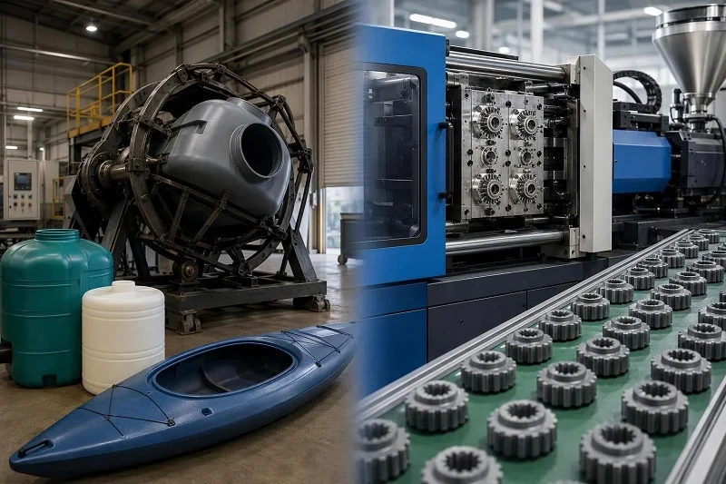
The choice between rotational molding vs инъекциялық құю usually comes down to four questions about the part itself: is it hollow or solid, how large is it, how many do you need per year, and how tight do the tolerances have to be. A one-piece tank and a precision connector housing sit at opposite ends of that grid, and the process that suits one will not suit the other.
This comparison works through the two cycles step by step, then applies them to applications, materials, tolerances and wall thickness, tooling economics, and the neighboring processes — blow molding, thermoforming, and CNC machining — that sometimes compete for the same part. It closes with what to confirm before committing to production tooling, what regulated work adds to the picture, and how a manufacturing partner can support both processes.
Ротациялық қалыптау vs Injection Molding at a Glance
The matrix below is a starting point for orientation, not a verdict. Each row is explained in the sections that follow, and several rows depend on conditions — part size, resin, mold construction — that a single cell cannot carry.
| Фактор | Айналмалы қалыптау | Инъекциялық қалыптау |
| Бөлшек түрі | Hollow, seamless, one piece | Solid, detailed, often multi-feature |
| Типтік мөлшері | Medium to very large; one-piece tanks up to 30,000 gallons have been produced | Small to medium, limited by clamp force |
| Дыбыс ауқымы | Roughly 100 to 10,000 parts per year | Roughly 1,000 to millions per year |
| Цикл уақыты | Tens of minutes (typically 10–60 minutes for heat and cool) | Seconds to about a minute |
| Құралдар құны | Low to medium; unpressurized shell molds | High; hardened steel, multi-cavity tools |
| төзімділік | Looser; roughly ±1 mm typical, tighter with optimization | Tight; ±0.005 in commercial, ±0.002 in precision on small features |
| қабырға қалыңдығы | Uniform, thick, set globally by shot weight | Variable by design, typically 0.040–0.140 in |
| Материал ауқымы | Narrow, mainly polyethylene | Very wide thermoplastic range |
Read the table as a set of questions rather than answers. If your part is hollow and large, the left column is where the reasoning starts; if it is solid, detailed and needed in the hundreds of thousands, the right column is. The middle ground is where a quote comparison at your actual annual volume does more work than any table.
How the Two Processes Work
The differences in the matrix are not arbitrary. They follow from how each process fills a mold, and understanding the cycles makes the rest of the comparison predictable rather than memorized.
The Rotational Molding Cycle
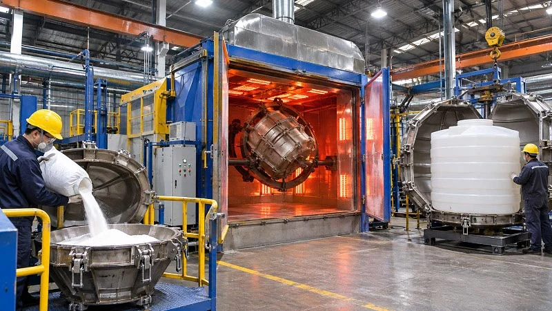
Rotational molding runs in four stages. An operator weighs plastic powder into the mold and closes it; that powder weight, the shot weight, sets the wall thickness of the finished part. The mold then moves into an oven and turns slowly on two axes — biaxial rotation, usually at less than 10 rpm, with the major axis typically rotating faster than the minor one. As the mold heats, the powder coats every internal surface and fuses into an even layer of melt. The mold then leaves the oven and cools while still turning, with fans and sometimes water spray accelerating heat transfer, until the polymer solidifies. Finally the part is removed, often while still warm, and the mold is refilled.
The mold itself is an unpressurized shell because the process runs at atmospheric pressure. That is why rotomold tooling can be built with relatively thin walls and at lower cost than tools for processes that must resist internal pressure. It is also why the process produces parts with relatively low residual stress: the plastic is never forced or sheared. The trade-off is time — a full heat-and-cool sequence typically runs 10 to 60 minutes — and throughput comes from running several molds at once on a carousel or shuttle machine rather than from shortening any single cycle.
The Injection Molding Cycle
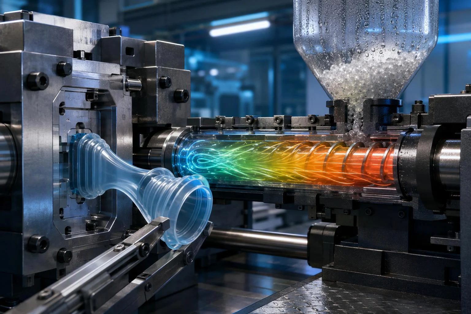
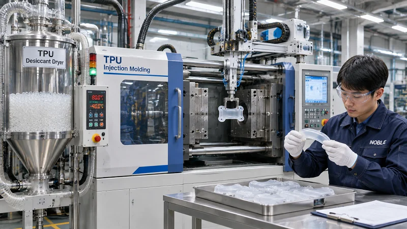
Injection molding clamps a closed steel mold, injects molten thermoplastic into the cavity under high pressure, packs additional melt in to compensate for shrinkage as the part cools, then opens the mold and ejects the finished part. A typical cycle runs 15 to 60 seconds.
The packing and holding phase, entered at roughly 95–98% fill, is what determines sink marks, dimensional repeatability and residual stress — not the fill itself. Cooling normally accounts for 50–80% of total cycle time, and cooling time scales with the square of wall thickness: doubling the wall quadruples the cooling term, while halving it cuts cooling by about 75%. That quadratic relationship makes wall section the dominant cost lever in part design.
Tooling dominates the economics. A single-cavity aluminum bridge tool, a single-cavity P20 steel tool, and a 16-cavity hardened H13 tool with a hot runner differ by more than an order of magnitude in both price and break-even volume. Per-part cost is then machine rate × cycle time ÷ cavity count, plus material, plus scrap — which is why cavity count is a design decision, not just a purchasing one.
Where the Two Cycles Diverge
Four structural differences explain most of what follows. First, pressure: injection molding forces melt into a cavity under high pressure, while rotational molding relies on gravity and heat inside an unpressurized shell. Second, part form: injection molding produces solid parts, rotational molding produces hollow, seamless ones. Third, time: seconds versus tens of minutes. Fourth, wall control: injection molding sets wall locally through the cavity geometry, so a designer can thicken one rib or thin one panel; rotational molding sets wall globally through shot weight, so if one region needs more material, the entire part gets it.
That last point is the hinge for the rest of this article. It explains why rotomolded parts tend toward uniform walls, why local features are handled with kiss-offs and corrugations rather than thickened sections, and why the tolerance conversation later looks so different for the two processes.
Қолданылуы: Әрбір процесс сәйкес келетін жер
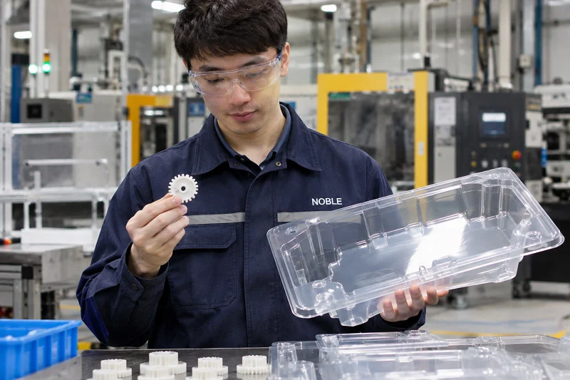
Applications follow from the cycles. Rotational molding is suited to hollow, seamless, large parts at low to medium көлем; injection molding is the default for solid, detailed parts made in the thousands to the millions. Neither is a universal rule for a whole product category — plenty of categories contain parts made both ways.
Typical Rotational Molding Products
Rotomolded products are characteristically hollow and often large: commercial, industrial and agricultural storage tanks from about 5 gallons to 22,000 gallons; containers for packaging and material handling; tote bins and water-softening tanks; playground equipment; kayaks and canoes; road barriers, buoys and traffic barricades; planters, furniture, display cases and recycling bins; and industrial covers and housings. Sizes run from handheld parts to one-piece tanks as large as 30,000 gallons.
Some of these applications are standardized. ASTM D1998 covers flat-bottom, upright, cylindrical polyethylene tanks molded in one-piece seamless construction by rotational molding, for above-ground vertical installation at atmospheric pressure, in capacities from 1,900 L (500 gal) up. Its scope is deliberately bounded: it does not cover vessels intended for pressures other than atmospheric, portable tanks, or service with liquids heated above their flash points, and it directs users to other standards for seismic, wind, agitation and higher-temperature service. That boundary is a useful reminder that a standard covering a product family does not automatically cover every installation of that product.
Typical Injection Molding Products
Injection molding covers solid, detailed, high-volume components: enclosures, connectors, closures, gears, medical disposables, and most molded consumer goods. It is also the process behind many cosmetic and multi-feature parts, since the pressure available fills intricate geometry and reproduces fine surface detail. Precision and repeatability matter most where parts mate, seal, carry load or move against one another — those are the dimensions that justify tight tolerances, and the ones where injection molding’s capability is usually the deciding factor.
Overlap Cases and How to Break the Tie
Some parts could plausibly go either way: a medium-sized hollow housing, a thick-walled solid component, a low-volume enclosure. Four tie-breakers usually settle it.
Annual volume comes first. Below roughly a thousand parts a year, injection tooling is hard to amortize; in the low thousands, the answer depends on part size and cavity count. Second, tolerance: if the critical dimensions need to hold within a few thousandths of an inch, injection molding is the more natural fit, while rotomolding’s shrinkage behavior makes a multitude of tight dimensions difficult to hold simultaneously. Third, wall thickness and uniformity: a part that needs a locally thick section is a poor rotomolding candidate, while a part that needs an even, thick wall across a large hollow form is a poor injection candidate. Fourth, and most basic, is whether the part is hollow: if it must be one seamless piece with an enclosed volume, rotational molding is the shorter route.
Where two processes remain plausible after those four questions, request quotes for both at your actual annual volume and compare piece-part economics rather than tooling price alone.
Materials: What Each Process Can Run
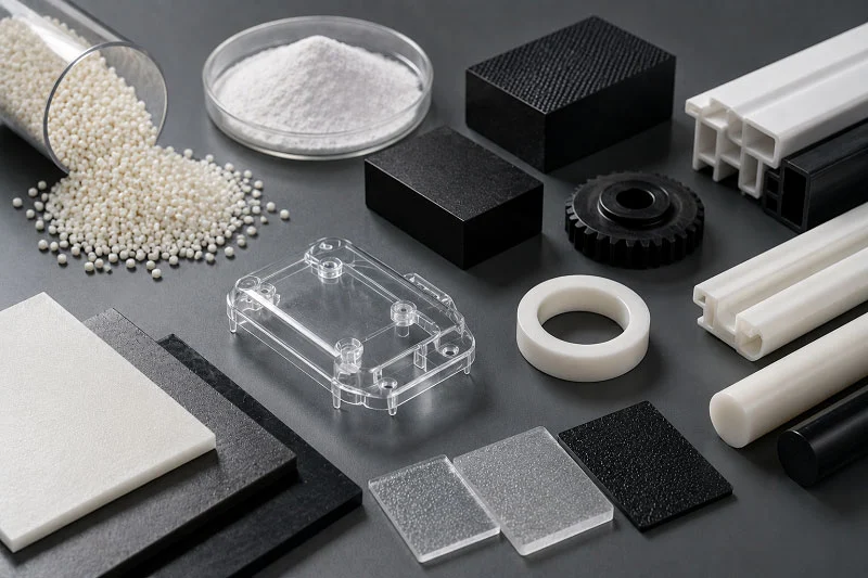
Material compatibility is one of the sharpest differences between the processes, and it constrains the decision earlier than many buyers expect.
Materials for Rotational Molding
The range of plastics suitable for rotomolding is relatively limited, and one polymer type predominates. According to a polyolefin supplier’s guide to rotational molding, approximately 84% of all resin used in the process is polyethylene, with the remaining share spread across polycarbonate, nylon, PVC, polyesters, polypropylene and smaller categories. Polyethylene earns that position through easy grinding to powder, thermal stability with proper stabilization, good low-temperature impact strength, relatively low cost, and — especially in crosslinkable grades — excellent chemical resistance for agricultural and industrial tanks.
Other materials serve specific needs: XLPE for extra toughness, PVC for flexible parts, nylon for heat and chemical resistance, polycarbonate for clarity, and polypropylene for stiffness. Two constraints apply across the list. The resin must be supplied as powder fine enough to melt and coat the mold evenly, and long oven times create a thermal-degradation risk, so materials must be stabilized for the cycle they will see. Some specialty materials, particularly amorphous polymers such as polycarbonate, can lose physical performance if sections are too thick, so maximum as well as minimum wall recommendations are worth checking.
Инъекциялық қалыптауға арналған материалдар
Nearly any thermoplastic runs on injection molding — ABS, PP, PC, nylon, acetal, PEEK — plus glass- and mineral-filled compounds, and thermosets on modified machines. The practical wall range for most thermoplastics is 0.040–0.140 in (1.0–3.5 mm). High-flow resins such as polypropylene, acetal and LCP fill down to about 0.025–0.030 in (0.64–0.76 mm), while low-flow polycarbonate wants at least 0.040 in (1.02 mm).
Uniformity matters more than the absolute wall number. Abrupt wall transitions freeze flow and warp the part, so tapers over about three times the step are preferred, and ribs are typically held to about half the nominal wall to avoid sink marks on the opposite face.
Material Choice and Part Performance
The same polymer can behave differently depending on the process. Polyethylene molded by rotation is not the same material as polyethylene injection molded into a thin-walled part: grade, additive package, melt index and thermal history all differ, and so do the resulting impact strength, stiffness and environmental stress-crack resistance. That is why material selection and process selection should be made together rather than in sequence. If chemical resistance is the driving requirement, crosslinked polyethylene in a rotomolded tank may be the natural answer; if clarity or high stiffness in a thin section is the requirement, an injection-molded grade is more likely to deliver it. UV stability, impact strength and food-contact suitability are all properties that can be engineered into either process, but the specific grade and the process that can run it have to be chosen as a pair.
Tolerances, Wall Thickness and Design Rules
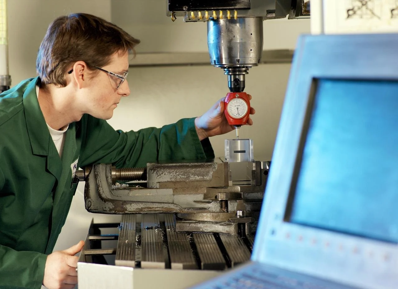
Tolerances and wall thickness are where design intent meets process capability, and the numbers below are the ones to design against.
Recommended rotational molding tolerances for polyethylene rotogrades, in inches per inch of dimension, for inside and outside sections. Outside dimensions are free-formed as the part shrinks away from the mold, so they carry a wider band than inside sections. Values are design-guide recommendations, not guarantees for a specific part.
Wall Thickness Capability
Rotational molding’s practical wall range is about 0.060–0.500 in (1.5–12 mm), with 0.125–0.250 in (3–6 mm) covering most tanks and containers; larger parts have been made with walls up to two inches and more. Wall is set by shot weight and applies to the whole part, so local thickening is not possible — if one area needs more material, the entire part gets it. Expect thickness variation on the order of ±10–20% around nominal: ±20% is the normal commercial expectation, reducible to about ±10% with tighter process optimization, usually at the cost of development time and potential scrap.
Nominal walls below about 0.075 in carry a real risk that some areas of the part will be inadequate or even zero thickness, so a minimum wall should be specified explicitly. One further design consequence: increasing wall thickness reduces the internal volume of a tank or container, which is negligible in large vessels but can matter in small ones.
Injection molding’s practical range for most thermoplastics is 0.040–0.140 in (1.0–3.5 mm), with high-flow resins reaching down to about 0.025–0.030 in and low-flow resins needing more. Because wall is set by cavity geometry, local variation is a design choice rather than a process limitation.
Қол жеткізуге болатын төзімділіктер
The ARM Design Guide gives recommended tolerances for polyethylene rotogrades as inches per inch: an ideal design at ±0.010 on inside sections and ±0.020 on outside sections; a commercial design at ±0.008 inside and ±0.010 outside; and a precision design at ±0.004 inside and ±0.005 outside. Outside dimensions are free-formed as the plastic shrinks away from the mold, so they are harder to control than inside sections, which shrink onto the cavity. Small parts are easier to hold than large ones, and thin-walled parts easier than thick-walled ones.
Injection molding typically holds ±0.005 in (±0.127 mm) commercial on features under 1 in, ±0.002 in (±0.05 mm) precision, and ±0.1–0.2% of dimension on larger parts, with additional tolerance for anything spanning a parting line or a side action. Shrinkage, not machining, sets the limit in both processes. Datasheet shrink values come from standard test specimens and cannot predict absolute values in real parts with varying flow paths, wall thicknesses and process conditions, so the shrink factor should be owned by the molder for the specific geometry and resin. Semi-crystalline and filled resins shrink directionally, which is why a title-block tolerance that is easy on a small feature can be out of reach on a long one.
Design Rules That Follow
For rotomolding, specify a minimum wall rather than leaving it to the shot weight, crown or corrugate large flat panels (polyethylene shrinks 3% or more, and an unsupported flat will warp or oil-can), use kiss-offs and corrugations for stiffness since there is no pressure available to fill a narrow rib, and allow generous radii — 0.5 in (13 mm) or more outside, with inside radii about twice the outside. Draft should be 1–2° per side externally and 3–5° over any core.
For injection molding, identify the few dimensions that genuinely control fit, assembly, sealing or motion, give those direct tolerances and mark them critical, and let everything else ride on a general tolerance. Use GD&T to state requirements relative to datums so designer, molder and inspector read the same intent, and plan steel-safe on high-risk dimensions — leaving extra steel or an insert so the tool can be adjusted after first sampling instead of welded or recut. Get that adjustment cost onto the mold quote up front.
For both processes, plan for shrinkage after molding: rotomolded parts can be placed in cooling fixtures while still warm to hold critical dimensions, and shrinkage jigs are a standard technique. Mold maintenance and release-agent discipline — a well-maintained permanent coating, or a standardized schedule for semi-permanent agents — affect dimensional consistency as much as any process setting.
Tooling, Cost and Lead Time
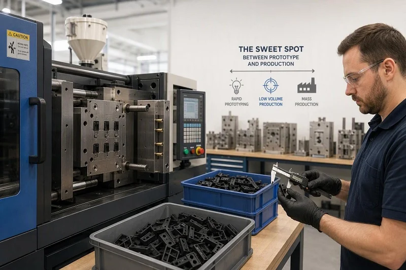
Economics is where the two processes most often diverge for a buyer, and it is also where blanket statements do the most damage. The honest answer is that each is cheaper in its own territory.
Tooling Cost and Construction
Rotational molds are unpressurized shells, which is why they are the cheapest tooling of any hollow-part process at size. Construction is typically fabricated steel for large simple shapes or cast aluminum where detail matters; aluminum molds are usually thicker than equivalent steel molds but do not much affect cycle time, because aluminum’s thermal conductivity is many times greater. Cast molds carry additional cost from the pattern needed before casting, while fabricated steel or aluminum molds for less complex parts are less expensive. Mold construction method also affects precision: CNC molds can be made to very tight tolerances, cast aluminum molds are subject to greater dimensional variance, and fabricated molds generally have the least precision.
Injection molds are built to resist high internal pressure and are typically hardened steel, often multi-cavity and sometimes with hot-runner systems. The spread is enormous: a simple single-cavity mold might run $3,000–$10,000, while a complex multi-cavity steel mold can exceed $300,000. Tooling lead times follow the same pattern — weeks for simple tools, months for complex steel.
Цикл уақыты және бір бөліктің құны
In injection molding, per-part cost is machine rate × cycle time ÷ cavity count, plus material, plus scrap. Machine cost is usually 30–50% of total cost and is dominated by cycle time and cavitation; material is usually 20–40%. Because cooling scales with the square of wall thickness, wall section is the single biggest lever a designer controls. More cavities reduce cost per part but increase mold complexity and cost, and cavity count is limited by mold design — side actions, layout and mold base size all constrain it.
In rotational molding, cost is driven by shot weight and oven time. Thicker walls mean more material and longer cycles, and a jump from 6 mm to 8 mm raises the powder charge by about a third and can add 8 to 10 minutes of oven time plus additional cooling. Throughput comes from running multiple molds on a carousel or shuttle machine, so the relevant unit is often the arm turn rather than the individual part. Servicing — load, unload, spray, close — typically takes 4 to 8 minutes per arm on a manual carousel and belongs in the cycle calculation.
Volume Break-Even
Rotational molding is generally economical from roughly 100 to 10,000 parts per year; a typical medium-sized mold run 24/7 produces approximately 5,000–10,000 parts per year, and higher quantities are reached by adding molds. Injection molding runs from about 1,000 parts per year to millions, with the high end where its tooling amortizes most comfortably.
The break-even logic is straightforward once the cost structure is clear. Rotomolding front-loads less capital and carries a higher per-part cycle cost; injection molding front-loads more capital and carries a lower per-part cost once volume is sufficient. For hollow parts specifically, blow molding becomes competitive above roughly 10,000 parts a year, where its much shorter cycle dominates — though cases of a product converting from rotomolding to blow molding as volumes grow are relatively rare, because a design that fully exploits rotomolding’s advantages can be difficult to transfer to a more restrictive process.
Rotational Molding vs Injection Molding Against Other Processes
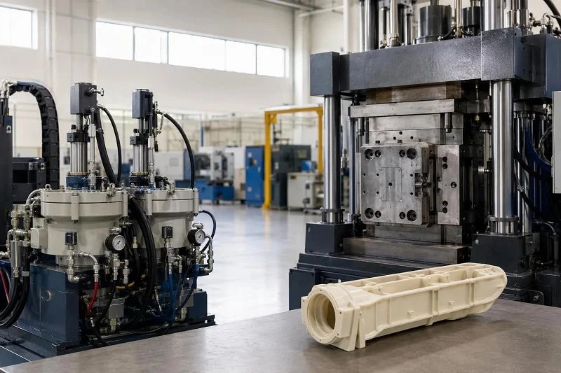
Rotational molding vs injection molding is not the only comparison a buyer may need. If neither feels like a clean match, the neighboring processes are worth checking before requesting quotes.
Соққы қалыптау
Blow molding is the other main hollow-part process. It runs a shorter cycle and becomes economical at higher volumes — roughly 10,000 parts a year and up — while rotational molding offers lower tooling cost at the same size, uniform walls including in the corners, and no pinch-off seam. Rotomolded parts also tend to thicken on outside corners, whereas blow molding and thermoforming tend to thin there, which matters where those corners see stress. For a large hollow part at low to medium volume, rotomolding is usually the shorter route; for a smaller hollow part at high volume, blow molding’s cycle time usually wins.
Термоформалау
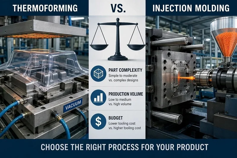
Thermoforming forms heated sheet against a mold, which gives it low tooling cost — aluminum tooling typically $500–$15,000 — and short development cycles, making it attractive below roughly 3,000–5,000 units and for very large parts. Its walls are thin (about 0.010–0.080 in), thickness control is around ±20%, and achievable tolerances run about ±0.015–0.050 in, with 20–50% material scrap from web and trim. Injection molding’s economics become compelling above about 5,000 units, where faster cycles and lower per-part labor overcome the higher tooling, and its tolerances (±0.003–0.015 in in the same comparison) and thin-wall capability are tighter. Thermoforming is also often used for initial development and prototyping before committing to injection tooling.
CNC өңдеу and Prototyping
CNC machining cuts parts from solid stock rather than forming them in a mold. It produces initial parts in one to three days, iterates very fast, and scales linearly — no tooling to amortize — which makes it the natural choice for prototypes, low-volume bridge production, and tight-tolerance features that exceed molding capability. It complements rather than replaces molding: a machined prototype validates geometry and fit, a machined bridge tool or insert covers the gap before production tooling is ready, and hybrid strategies that machine tight-tolerance features into molded parts can take the strengths of both. What machining does not offer is the per-part economics of a mature molding process at volume.
Moving from Prototype to Mass Production
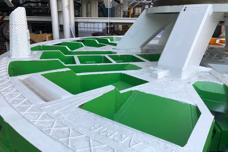
The transition from prototype to mass production is where many programs lose time and money, usually because a tooling decision was made before the design was validated. The sequence below is ordinary practice, not a guarantee of any particular outcome.
Validating the Design Before Tooling
Before production tooling is cut, confirm wall thickness, draft, shrinkage allowance and the critical dimensions. Wall thickness is the biggest cost lever in injection molding and the biggest strength lever in rotomolding, so it should be settled early. Draft needs to suit the process — 1–2° external for rotomolding, 1.5° per side for untextured injection molds, more for textured surfaces. Shrinkage allowance should come from the molder for the specific geometry and resin rather than from a datasheet, and critical dimensions should be identified and marked so capability and inspection can be built around them.
Prototype feedback changes tooling decisions in predictable ways. A printed or machined prototype confirms assembly clearances against real mating hardware and exposes wall, draft and gating issues while changes are still cheap. A design-for-manufacturability review at that stage is where tolerance decisions cost the least to change. For high-risk dimensions, plan steel-safe from the start so the tool can be adjusted after first samples.
Scaling Up Without Losing Quality
As volume rises, consistency becomes the product. In rotomolding that means mold maintenance to keep parting lines clean, disciplined release-agent application on a regular schedule with standardized technique, and attention to resin batch variation — shrinkage can vary from batch to batch, grade to grade and between colors, and reprocessed or off-grade material increases variability further. In injection molding it means process capability on the critical dimensions, a preventive-maintenance schedule for the mold, and inspection planning that matches the risk of each feature.
A single partner covering both prototyping and production can reduce handoff risk between the two stages, because the same team that validated the design is accountable for the tool and the parts. That is a structural advantage, not a guarantee — the capability still has to be demonstrated on your specific dimensions.
Regulated and Medical Considerations

Medical and other regulated parts add requirements around the process rather than changing the physics of it. The considerations below are general practice to plan for, not a claim that any certification guarantees a particular part outcome.
Құжаттама және бақылау
Regulated production depends on a paper trail that connects a shipped lot to its evidence. Under FDA QSR / 21 CFR 820 and cGMP discipline, the Device Master Record and Device History Record are the documents that make that connection. In practice, buyers should expect lot-level material certificates, capability data on critical characteristics, and a traceability system that maps part to resin lot, machine and cycle so a recall investigation can actually run. ISO 13485 certification is useful evidence of supplier capability, but it should be read in context: confirm the certificate applies to the relevant legal entity and manufacturing location, that its scope covers the activities you are purchasing, and that critical operations are not performed elsewhere without adequate control. Certification is one input to qualification, not the whole assessment.
Материалды және процесті валидациялау
Material selection, wall thickness and process parameters all need validation for regulated parts. Resin should ship with its biocompatibility documentation — a USP Class VI test report or ISO 10993 biological evaluation — attached to the lot certificate; a molder can procure grades that carry the certification and keep the chain intact, but cannot certify a resin itself. Process validation should establish that the chosen process holds the critical dimensions statistically, with capability indices reported per critical feature.
The practical consequence is that process choice should follow the validation plan rather than precede it. If the validation plan requires capability on a set of tight dimensions, that requirement may point toward injection molding; if it centers on a large hollow device with a seamless wall, it may point toward rotational molding. Deciding the process first and writing the validation around it tends to create avoidable difficulty later.
Choosing NOBLE for Rotational Molding and Injection Molding
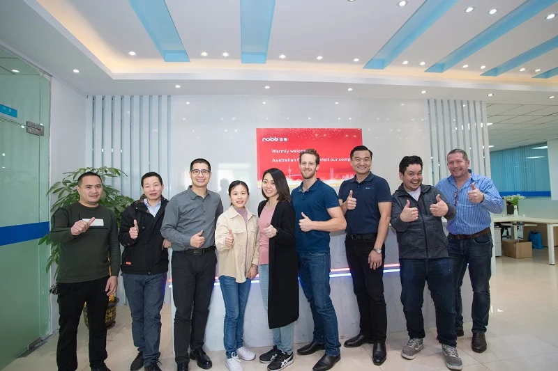
NOBLE is a Chinese contract manufacturer with strong service and professional processing capabilities, and we support both rotational molding and injection molding. Our role is to help customers complete prototyping and batch production efficiently — bringing a part from concept through tooling and into volume without the friction of coordinating several suppliers.
Дизайннан құрастыруға дейін бір серіктес
NOBLE provides a full service scope from design to assembly, not production alone. In practice that means design support and manufacturability input before tooling, prototyping to validate geometry and fit, tooling, production, and assembly. The value of that scope is continuity: the team that reviewed the design is the team that builds the tool and runs the parts, so decisions made at the prototype stage carry through to production rather than being re-litigated at each handoff. For programs that move between processes — a machined or printed prototype, then a molded production part — a single partner also removes the coordination cost of transferring drawings, tolerances and inspection criteria between vendors.
Prototyping and Mass Production Support
NOBLE supports both efficient prototyping and batch production. Our capabilities cover the range from design and prototypes to mass production of parts, and our technical and service team works with customers through the project rather than only at the quotation stage. Because we work across multiple manufacturing processes, the process recommendation can follow the part requirements — hollow or solid, low or high volume, loose or tight tolerance — rather than being constrained to whatever single process a supplier happens to run.
Сапа жүйелері және сертификаттау
NOBLE is certified to ISO 9001:2015 and ISO 13485:2016. In general terms, ISO 9001:2015 addresses quality management system requirements across the organization — process control, document control, corrective action and continual improvement — while ISO 13485:2016 adds medical-device-specific requirements around risk management, traceability, validation and supplier control. For a buyer evaluating a manufacturing partner, these certifications indicate that a documented quality system is in place and subject to audit. They do not, on their own, certify that any particular part will meet a particular tolerance or regulatory requirement; that still has to be demonstrated through capability data, first-article inspection and, where applicable, process validation on your specific part.
FAQs about Rotational Molding vs Injection Molding
How do I decide which process fits my part geometry and volume?
Start with the part itself. If it is hollow, seamless and large, and you need roughly 100 to 10,000 parts a year, rotational molding is the natural starting point. If it is solid, detailed and needed in the thousands to millions, injection molding is. If it could plausibly go either way, compare quotes at your actual annual volume rather than at a nominal quantity, and check tolerance and wall-thickness requirements against each process’s capability before deciding.
What do tooling cost and lead time look like for each process?
Rotomold tooling is an unpressurized shell — fabricated steel or cast aluminum — and is the cheapest tooling of any hollow-part process at size. Injection tooling ranges from a few thousand dollars for a simple single-cavity mold to more than $300,000 for a complex multi-cavity steel tool, with lead times from weeks to several months. In both cases, construction method and cavity count drive the spread more than part size alone.
Which materials are compatible with each process?
Rotational molding’s range is narrow and polyethylene-dominated — approximately 84% of resin used in the process is polyethylene, with XLPE, PVC, nylon, polycarbonate and polypropylene serving specific needs. Injection molding covers nearly any thermoplastic, including ABS, PP, PC, nylon, acetal and PEEK, plus filled compounds. The resin must also suit the process: rotomolding requires powder and tolerates long oven times only with properly stabilized material.
How do these two processes compare with blow molding, thermoforming and CNC machining?
Blow molding is the other hollow-part process, with shorter cycles and higher volume thresholds but less uniform walls and a pinch-off seam. Thermoforming offers low tooling cost and short development cycles for thin-walled, large, simple parts, but looser tolerances and higher scrap. CNC machining produces parts in days with no tooling, which suits prototypes, bridge production and tight-tolerance features, but not high-volume unit economics. Each complements molding rather than replacing it outright.
When should I move from prototype to mass production, and can one partner cover both?
Move when the design has been validated — wall thickness, draft, shrinkage allowance and critical dimensions confirmed — and when tolerance capability has been demonstrated on the actual geometry. Committing to tooling before that point is where most avoidable cost sits. A full-service partner can cover both stages; NOBLE’s scope runs from design through prototyping, tooling, production and assembly, which reduces handoffs between them.
What should I consider for medical or regulated parts?
Plan for documentation and traceability — Device Master and History Records, lot-level material certificates, and a part-to-resin-lot-to-machine traceability chain — and for validation of material, wall thickness and process parameters. Resin should carry its biocompatibility documentation on the lot certificate. NOBLE holds ISO 13485:2016 certification, which indicates a documented medical-device quality system; the specific part still needs its own capability and validation evidence.
қорытынды
The choice between rotational molding and injection molding follows from the part, not from a ranking. Hollow, seamless and large at low to medium volume points toward rotational molding, with its low tooling cost, uniform walls and freedom from residual stress. Solid, detailed and high-volume points toward injection molding, with its tight tolerances, broad material range and low per-part cost once tooling is amortized. Where the part sits in between, the tie-breakers are annual volume, tolerance requirements, wall thickness and whether the geometry is hollow or solid — and the answer is best confirmed with quotes at your actual volume.
If you are working through that decision, bring your part requirements to NOBLE. We support both rotational molding and injection molding, are certified to ISO 9001:2015 and ISO 13485:2016, and provide a full service scope from design to assembly. A scoped discussion of your geometry, volume and tolerance needs is the fastest way to establish which process fits — and what it will take to move from prototype to production.