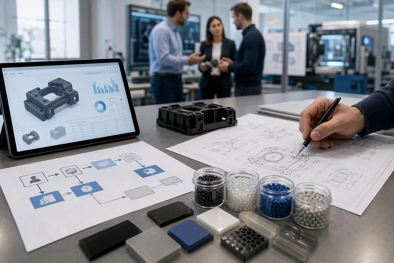
Injection molding manufacturing is the production system that turns thermoplastic resin into finished parts by melting it, forcing it into a closed tool under pressure, holding it while it solidifies, and ejecting the result. The machine is only one element. What determines whether a program succeeds is how five decision layers fit together: the part design, the tool, the resin, the process window and the quality plan. Change any one of them and the other four move with it — a thicker wall lengthens cooling, a glass-filled resin changes shrinkage and wear, a new gate location shifts where weld lines land.
This guide treats injection molding manufacturing as that connected system. It covers the process anatomy and where the time in a cycle actually goes, the design guidelines worth reviewing before steel is cut, a material selection sequence, the defects that design can prevent, a comparison against machining, 3D printing and urethane casting, tooling qualification and first-article inspection, quality certification, and how to evaluate a manufacturing partner. Each section is written to stand on its own, with cross-references where a decision in one area constrains another.
Last refreshed: November 2026. Cycle-time benchmarks, resin datasheet values, standards editions and regulatory references change; the closing section notes which figures age fastest and when to revisit them.
מה זה הזרקה ייצור?
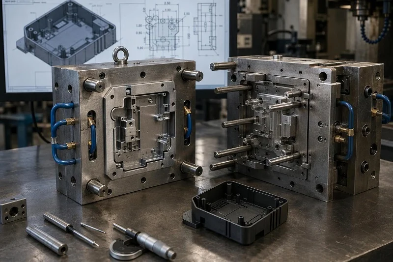
Injection molding manufacturing melts a thermoplastic resin in a heated barrel, injects it under pressure into a closed steel or aluminum mold, packs the cavity while the gate is still open, cools the part to ejection stiffness, and ejects it. The cycle then repeats, often every 15 to 40 seconds depending on wall section and material.
The process dominates high-volume plastic part production for three reasons. It repeats: once a process is qualified, shot-to-shot variation is small enough to hold tolerances across hundreds of thousands of parts. It is fast: a single cycle produces a complete part, and multi-cavity tools multiply output per cycle. And it produces net shape: ribs, bosses, snap fits, mounting features, texture and often living hinges come out of the tool in one shot, with no secondary assembly to join them.
What separates injection molding manufacturing from prototype-only methods is the tool. A hardened steel mold is a substantial capital commitment, and its cost has to be spread across the production run. That single economic fact explains most of the discipline in this guide: design decisions are cheap before the tool is cut and expensive after, and the design must be reviewed against what the mold can physically fill, cool and release.
The Core Machine, Mold and Material System
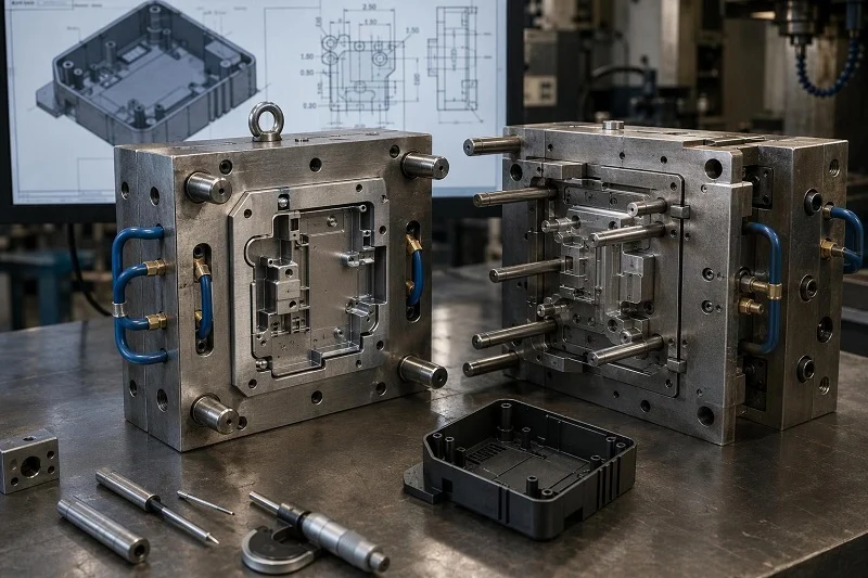
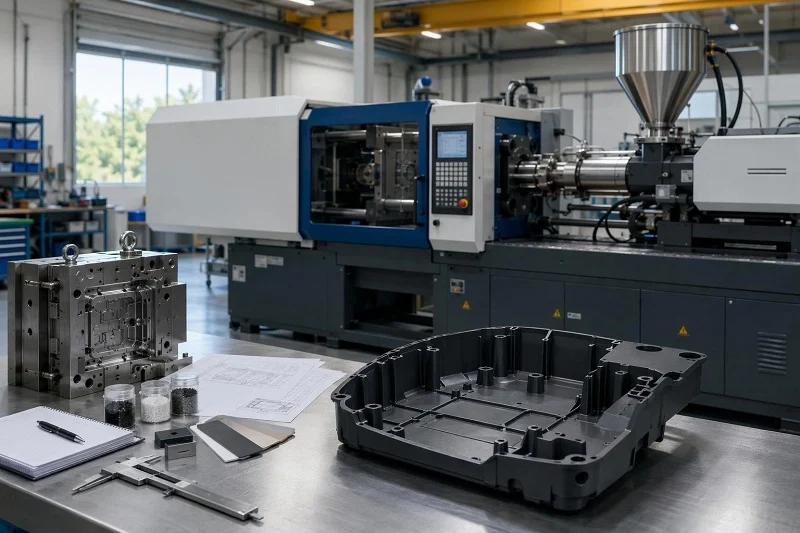
Three physical subsystems do the work. The יחידת הזרקה — screw, barrel, nozzle — melts, mixes and meters the resin, then drives it forward as a piston. The clamp unit — platens, tie bars, tonnage — holds the mold closed against injection pressure and opens it for ejection. The עובש contains the cavities that define the part, the runner and gates that deliver melt, the cooling channels that remove heat, and the ejection system that pushes the part out.
Machine selection is a fit problem, not a specification contest. Shot size must sit within the barrel’s usable capacity — running in the middle third of barrel capacity is a common practical target, because an oversized barrel gives long residence time and poor shot repeatability while an undersized one cannot deliver the shot or the velocity. Clamp tonnage must exceed the separating force the cavity projects, and tie-bar spacing must physically accept the mold. A mismatch in any of these constrains the process window before a single part is molded, and no amount of parameter tuning recovers it.
Where Injection Molding Manufacturing Fits in Product Development
The process enters a program after the concept has been validated. Early prototypes are usually machined or 3D printed, because those methods need no tool and deliver parts in days. Once the design is close to final, tooling is built, trial shots run through successive stages (commonly labeled T0 to T3), first-article inspection verifies the tool and process, and volume production begins.
The economic logic behind the design guidelines that follow is simple: a wall thickness, draft angle or boss position changed in CAD costs engineering time; the same change after the mold is hardened costs steel rework, re-qualification and schedule. Design review is the last cheap moment to change the part.
The Injection Molding Manufacturing Process, Step by Step
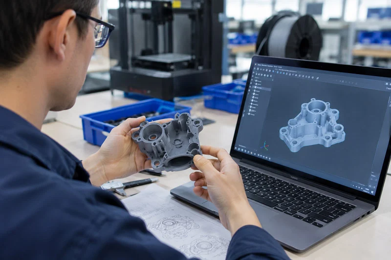
A production cycle runs through a fixed sequence, and each phase has a function, a controlling variable and a share of the clock. The phase breakdown below is the reference to return to when a cycle runs long or a part comes out wrong.
| שלב | נתח המחזור | מה קורה | מה שולט בזה |
| Mold close and clamp | part of 5–10% | Platens travel, clamp builds tonnage | Machine, safety settings |
| Injection / fill | % 5-15 | Screw rams forward, cavity fills | Gate design, wall thickness, melt viscosity, injection velocity |
| אריזה ואחזקה | % 20-30 | Pressure held while the gate freezes and shrink is compensated | Gate freeze time, part thickness, hold profile |
| התקררות | % 50-70 | Part solidifies to ejection stiffness | Wall thickness, cooling layout, mold temperature, material |
| Mold open and eject | part of 5–10% | Platens open, ejectors push the part out | Ejection design, robot, part geometry |
| Takeout, inspection, restart | % 5-10 | Robot removes part, sprue separated, safety gate cycles | Automation, layout, operator workflow |
Approximate cooling time by nominal wall thickness for common thermoplastics. Values are indicative and vary with resin, mold temperature and cooling-channel design; cooling time rises roughly with the square of wall thickness, so the curve shape is more reliable than any single value.
Clamping, Injection and Packing
Clamping closes the mold and builds tonnage before injection begins; safety settings govern the low-pressure close so a misaligned part cannot damage the tool. Fill follows: the screw advances at a controlled velocity profile, and the cavity fills from the gate outward. Fill time is set by gate size and location, wall section and melt viscosity — a thin wall far from the gate is the classic fill limitation.
Packing and holding keep pressure on the melt while the gate is still open, compensating for the shrinkage that occurs as the part cools. This phase typically consumes 20–30% of the cycle, and its floor is set by gate freeze time and part thickness rather than by the clock. A hold time longer than the gate needs adds seconds without adding packing; a hold time shorter than a thick section needs leaves sink and internal voids.
Cooling: The Dominant Phase
Cooling commonly accounts for 50–70% of cycle time, and it scales strongly with wall thickness — roughly with the square of thickness. A part at 3.0 mm carries about 2.25 times the cooling time of the same part at 2.0 mm. Indicative cooling times for common wall sections run from a few seconds at 1.0 mm to roughly half a minute at 3.0 mm, but the real number depends on the resin’s thermal diffusivity, the cooling layout, mold temperature and the stiffness needed at ejection. The table shape is reliable; the specific seconds are not a quote.
That relationship is why wall thickness is the buyer’s cost decision, not just the designer’s. Every extra millimeter of wall is paid for on every shot for the life of the tool. Where a locally thick region cannot be avoided, conformal cooling — channels that follow the part surface rather than being drilled in straight lines, produced by additive manufacturing of inserts or as hybrid machined-and-additive inserts — is the largest tooling-side lever available.
Ejection, Takeout and Restart
The mold opens, ejector pins or sleeves push the part off the core, and a robot or operator removes it, separates the sprue and restarts the safety cycle. Ejecting too hot is a quality risk, not just a speed gain: it locks stress into the part, which surfaces later as crazing, cracking at assembly or a drop-test failure that passed in the lab. Amorphous resins such as ABS and PC are especially sensitive to this.
Cavity balance matters here too. A family tool with unbalanced cavities runs at the pace of the slowest cavity, and output is limited by the least-filled one — the cycle is set by the worst cavity, not the average.
What Sets Cycle Time and How to Shorten It
The levers, roughly in order of return: wall thickness first, because cooling scales with its square; cooling layout and mold temperature second; gate freeze and hold profile third, since hold should end when the gate freezes, not when a timer expires; material viscosity fourth, since a higher-flow grade can shorten fill and packing; automation of takeout fifth; and balanced cavity fill throughout.
Two cautions apply to any cycle reduction. First, establish capability before compressing: run a capability study on the original process, change one variable, re-run, and accept the change only if capability holds on critical dimensions. A cycle reduction that widens the distribution until the low end falls out of tolerance has converted a saving into a sorting operation. Second, cycle time is not purely a cost variable — on some parts it affects weld-line position, flow-induced orientation and residual stress, so it is also a quality variable.
Design Guidelines for Injection Molding Manufacturing
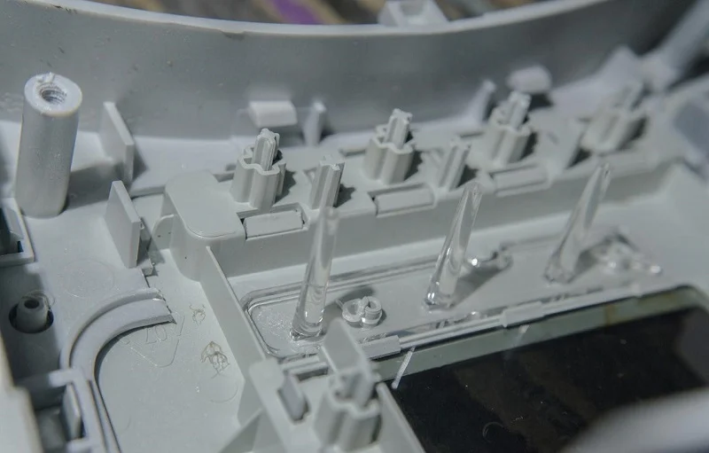
The guidelines below are organized by feature type and framed as a pre-tooling design review. Each states the design intent, the failure mode when it is ignored, and the question to ask before committing to tooling. Treat the numbers as starting points for discussion, not universal rules: limits vary by resin, tool construction and application, and a rule written without specifying the material is hard to apply with confidence.
עובי קיר ואחידות
כוונה: a wall thick enough to fill and carry load, uniform enough to cool evenly. מצב כישלון: thick sections cool slower, sink on the opposite face, warp and extend cycle time; abrupt thickness transitions create stress concentration and flow hesitation. Most consumer and industrial parts land at 2.0–3.0 mm, with high-flow resins such as PP and POM holding thinner sections and low-flow resins such as PC and glass-filled nylon generally wanting more. The stronger rule is uniformity — holding variation within roughly 25% of nominal for amorphous resins and 15% for semi-crystalline ones is common practice.
Review question: can the thick region be cored or ribbed instead of thickened? A correctly proportioned rib delivers stiffness at a fraction of the mass and cycle time.
Ribs, Bosses and Corners
כוונה: add stiffness and fastening points without creating mass. מצב כישלון: ribs thicker than about 0.6 times the nominal wall show sink on the opposite face; ribs thinner than about 0.4 times the wall risk incomplete fill at the tip. Semi-crystalline resins generally want the lower ratio because of higher crystallization shrinkage. Bosses follow the same sink rule, should be cored, should stand off from sidewalls and tie back with a gusset rather than fusing into the wall, and need enough outside diameter to resist hoop stress from a screw. Internal corner radii reduce stress concentration — sharp internal corners are the leading stress riser, and notch-sensitive resins such as PC punish them.
Review question: if a boss sits behind a cosmetic A-surface, will the back be cored, or will the sink be accepted and hidden with texture? That is a design-review decision, not a first-article discovery.
Draft, Undercuts and Ejection
כוונה: release the part cleanly. מצב כישלון: insufficient draft causes scuffing, drag marks and ejection force high enough to deform the part. Draft depends on the resin’s shrinkage onto the core, the surface finish and the feature depth; a high polish can increase vacuum adhesion, so deep polished cores deserve more draft, not less. Undercuts require side actions, lifters or bump-offs, each adding tool cost and maintenance.
Review question: can the undercut be redesigned as a snap fit that ejects in the pull direction? Internal undercuts are often cheaper with a lifter than a slide; external undercuts usually need a slide.
Gates, Runners and Weld Lines
כוונה: control the fill pattern. מצב כישלון: gate type and location determine where flow fronts meet, where weld lines form and how the part packs. Weld lines are weakened by incomplete knitting of the flow fronts, and they are also cosmetic. Gate placement can move them to non-critical areas; gate count and size affect fill pressure and freeze time. Hot runners eliminate sprue cooling and sprue handling and can cut several seconds from a cycle, at higher tool cost and complexity; cold runners are simpler and suit many programs.
Review question: has a mold flow analysis been run to show where the fronts meet and where air will trap? It is a short exercise relative to the cost of re-cutting a gate.
סובלנות והתכווצות
כוונה: specify what the process can hold. מצב כישלון: molded dimensions depend on resin shrinkage, which varies by material, by direction in fiber-filled resins, and by process conditions. Amorphous resins such as ABS and PC shrink roughly 0.4–0.7% and about equally in every direction; semi-crystalline resins such as PP and POM shrink more and less predictably; a 30% glass-filled nylon shrinks around 0.3% along the flow and closer to 1.0% across it. Specifying machining-grade tolerances on a molded part invites cost and dispute.
Review question: do any tight tolerances span a parting line or depend on two cavities? Those deserve early engineering review before the tolerance is committed.
A Pre-Tooling רשימת בדיקה לסקירת עיצוב
Work through these in order; each is cheaper to resolve now than after steel is cut.
- Nominal wall and thickness transitions reviewed for uniformity.
- Rib and boss proportions checked against the nominal wall, with bosses cored and gusseted.
- Draft applied to every vertical face and checked against the final texture specification.
- Undercut count and cost confirmed, with redesign options considered first.
- Gate location and weld-line risk reviewed, ideally with a flow analysis.
- Tolerance stack compared against process capability, with critical dimensions called out.
- Cosmetic-surface definition agreed, including where sink may be accepted and textured.
- Material-specific shrinkage confirmed for the actual resin grade.
Choosing Materials for Injection Molding Manufacturing
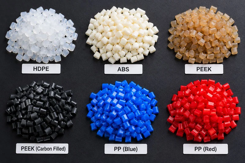
Material selection is where the largest performance differences are locked in, and where the cost of a late change is highest. The stakes are concrete: a 30% glass-filled PA66 delivers roughly 185 MPa tensile strength at 23 °C per ISO 527, while unfilled PP reaches roughly 35 MPa under the same test condition — a difference wall thickness changes alone cannot close. Datasheet values are only comparable at matched test conditions, and they are measured on molded test bars, not on your part geometry.
The Five-Filter Selection Framework
Apply the filters in this order, because a resin that fails an earlier one need not be evaluated against later ones.
| סינון | שאלת הליבה | מדדי מפתח | תוצאה של כישלון |
| 1. מכני | Does the resin survive the load case? | Tensile strength (ISO 527), flexural modulus (ISO 178), notched impact (ISO 180) | Part deforms, cracks or fractures in service |
| 2. תרמי | Does it hold shape at service temperature? | Heat deflection temperature at 1.8 MPa (ISO 75), Vicat (ISO 306) | Softening, warping, loss of dimensional tolerance |
| 3. Chemical / environmental | Does it resist the fluids, UV and moisture in use? | Compatibility data, UV exposure hours, moisture absorption (ISO 62) | Stress cracking, embrittlement, swelling, discoloration |
| 4. עיבוד | Does it fill the mold and hold tolerance at target cycle time? | Melt flow rate at stated conditions (ISO 1133-1), mold shrinkage, drying requirements | Short shots, warpage, dimensional scatter, long cycles |
| 5. רגולציה | Does the grade pass the required certifications? | Flammability rating at minimum thickness, food-contact regulation, biocompatibility, substance restrictions | Product cannot ship; compliance failure found at or after trial |
Two scope rules matter. A melt flow rate is incomplete without its test temperature and load. And a flammability rating at one thickness does not transfer to a thinner wall — minimum and maximum thicknesses covering the claimed range must be tested separately, so a rating at 1.6 mm does not guarantee the same classification at 0.8 mm.
Matching Resin Families to Common Applications
The table below gives typical starting points for evaluation, not exclusive rules. Parts that span categories stack the corresponding filters.
| בקשה | מסנן ראשי | Typical candidates | בדרך כלל נמנעים | למה |
| Structural brackets, clips | Mechanical: high modulus | Glass-filled PA66, glass-filled PPS | Unfilled PP | Deflects under sustained load; creep at room temperature |
| מארזי אלקטרוניקה | Thermal plus regulatory | Flame-retardant PC, flame-retardant ABS | פום | Cannot achieve a V rating; formaldehyde during combustion |
| Living hinges, snap fits | Mechanical: fatigue | הומופולימר PP | PA66, PBT | Crack at tight hinge radii |
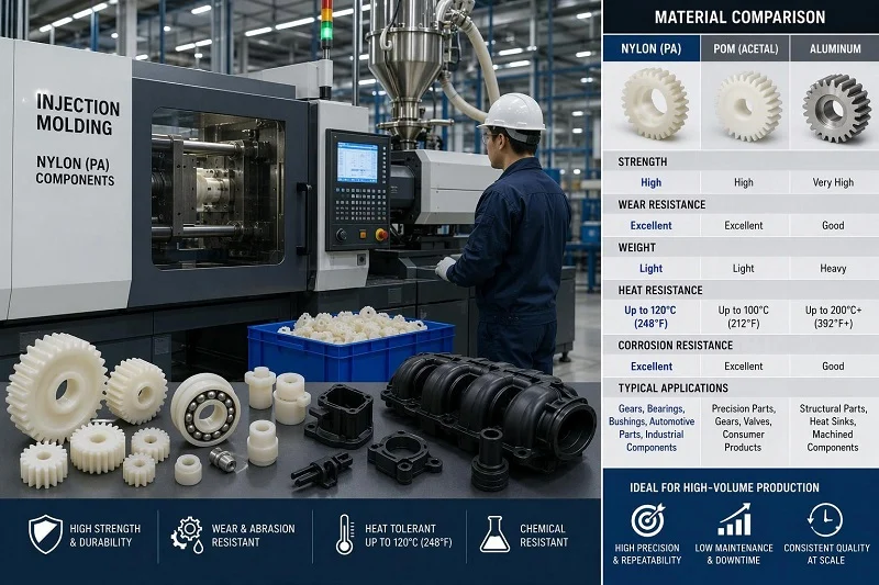
| גלגלי שיניים, מיסבים | Chemical plus low friction | POM, PA66 | PC | Stress-cracks on lubricant contact |
| בתי מכשור רפואי | Regulatory first | Medical-grade PC, PEEK | General-purpose ABS | No biocompatibility certification; colorant migration |
| מיכלי מגע עם מזון | Regulatory first | Food-contact PP, food-contact PC | POM, PBT | Extraction test failures under food-contact conditions |
A food-contact structural hinge, for example, needs a PP grade that passes both the fatigue requirement and the food-contact extraction test at the target wall thickness.
Moisture, Drying and Process Readiness
Hygroscopic resins absorb moisture into their molecular structure. Nylon, PC, PET/PBT and ABS fall in this group and must be dried to the resin supplier’s specified temperature and time. Undried material undergoes hydrolysis during processing, which breaks polymer chains and degrades mechanical properties, and produces cosmetic defects such as splay and silver streaks plus viscosity drift that destabilizes the process. Drying is cheap relative to the scrap it prevents, but it adds hours to lead time and requires storage discipline.
Hydrophobic resins such as PP and PE do not require pre-drying under normal conditions, which simplifies planning, but they can still be contaminated by direct water contact and need protection in storage and transport. Either way, confirm the drying protocol, the target moisture level and the verification method before the first production run.
Material Selection and Total Cost
Resin choice sets mold steel grade, gate geometry, cycle time and per-part cost before tooling is cut. A higher-performance resin may allow thinner walls and faster cycles; a cheap resin that forces thick walls can cost more per part over the tool’s life. A high-flow grade that cuts cycle time can beat a cheaper resin on total cost per part, and specifying a flame class after the tool is cut can force a different grade with different shrinkage and flow, invalidating the tool design. Call the flame class on the drawing before the design review, and let the tool be quoted against the actual grade.
Preventing Common Injection Molding Defects Through Design

Most defects are predictable consequences of thickness, fill pattern, cooling and material behavior. That means they can be designed out rather than debugged at trial. The four families below account for a large share of the questions that arise between design freeze and first article.
סימני כיור
Sink marks are dents or depressions on the surface, and they follow local mass. A thick boss, rib or wall section cools last; the outer skin solidifies first and is pulled inward by the slower-cooling material beneath it. Prevention is geometric: core out thick sections, proportion ribs to the nominal wall, and place gates so the thick region can be packed. Where coring is impossible behind a cosmetic surface, accept the sink and specify a texture that hides it — decided in design review, not at first-article inspection.
עיוות
The root cause is differential shrinkage. Uneven wall thickness, asymmetric cooling, fiber orientation and gate position all bias shrinkage in one direction, so a box that should have straight walls curves inward. Prevention: uniform walls, a balanced cooling layout, symmetric geometry, and gate placement that fills evenly. In glass-filled resins, wider rib spacing and symmetric gating reduce the flow-versus-cross-flow shrinkage differential that pulls parts out of shape.
Weld Lines and Flow Marks
Weld lines form where flow fronts meet and fail to knit completely, leaving a cosmetic mark and a locally weakened section — weld lines can reduce local tensile strength substantially depending on resin and gate location, so request weld-line data before finalizing a multi-gated part. Flow marks come from melt cooling prematurely against the mold wall. Prevention is mostly gate strategy: gate location and count determine where fronts meet, and wall-thickness transitions and material flow behavior determine how well they knit. Where a weld line cannot be moved off a prominent surface, a heavier texture or paint can hide it.
צילומים קצרים ומילוי לא שלם
A short shot is a fill-limitation problem: thin walls far from the gate, insufficient injection pressure or velocity, trapped gas, poor runner balance, or a material whose flow rate does not suit the wall section. Prevention starts with the wall-section review and gate sizing, plus adequate venting to release trapped air. Process settings are the final adjustment, not the first — a part that cannot fill because of its wall geometry will not be rescued by turning up the pressure.
Injection Molding Manufacturing Compared with Other Processes
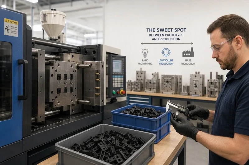
Injection molding manufacturing is one option among several, and the right choice depends on volume, geometry, material and tolerance. The framework below organizes the comparison around those four variables.
תכולה Economics and the Break-Even Point
Injection molding front-loads tooling cost and minimizes per-part cost; machining and 3D printing have low or no tooling and higher per-part cost. The crossover is where the amortized tooling cost plus low unit cost falls below the tooling-free alternative.
A worked example of the logic: a plastic enclosure with a 50,000-unit lifecycle favors molding on unit cost, but if the validation phase needs only 75 units, committing to production tooling at that stage carries real financial risk. A tooling-free or low-cost-tooling process can deliver production-representative parts for a fraction of the tooling commitment at that volume, and molding’s effective unit cost dominates once volume reaches the tens of thousands. The numbers are an illustration of the logic, not a quote — the crossover depends on part size, tool complexity and material, so run the comparison for the specific part.
Geometry, Tolerance and Material Freedom
הזרקת דפוס handles complex, thin-walled, integrated geometry in one shot, with excellent molded surface finish, but cannot economically serve very low volumes and needs draft and uniform walls. Typical tolerances run around ±0.05–0.2 mm, and the material range is thermoplastics.
עיבוד CNC holds tight tolerances — around ±0.025 mm is typical — and offers an exceptionally broad material range including metals and engineering plastics, which matters when a certified alloy is required. It is subtractive and slower per part at volume, and cannot produce fully enclosed internal cavities.
הדפסת 3D offers the most geometric freedom, including lattices and internal channels, with the fastest time to first part, but properties are direction-dependent and the production-material range is narrower.
יציקת אורטן bridges low-volume production-representative parts, typically a few hundred units, using low-cost silicone molds, with tolerances looser than molding or machining.
A Process Selection Matrix
| נפח אופייני | סיבוכיות גיאומטריה | Tolerance need | דרישת חומר | Starting recommendation |
| 1-100 | כל | Loose to moderate | Prototype-representative | הדפסת תלת מימד או עיבוד CNC |
| 50-500 | לְמַתֵן | לְמַתֵן | Production-representative plastic | Urethane casting or machining |
| 100-5,000 | בינוני עד גבוה | הדוק | Broad, including metal | CNC machining; aluminum tooling for plastic bridge volumes |
| 1,000–millions | High, net shape | לְמַתֵן | תרמופלסטיים | הזרקת דפוס |
| 10,000 + | High, net shape | לְמַתֵן | מַתֶכֶת | למות ליהוק |
This matrix is a starting point. The final choice depends on the specific part, program timing and total delivered cost including finishing and secondary operations, which are among the most commonly overlooked cost drivers in process selection.
Tooling, Trials and First-Article Qualification

Between design freeze and mass production sits a sequence of tool build, trial shots, process validation and first-article inspection. First-article inspection (FAI) is a structured dimensional and material verification of sample parts produced from the actual production tooling, run under full production conditions. It is not a prototype check and not a trial-shot review; it is a formal quality record generated from parts made at production speed, on production tooling, with production-approved material.
Tool Build and Trial Stages
Tool manufacture is followed by successive trial shots, commonly labeled T0 through T3. Each stage has a purpose: the first confirms that the mold fills and ejects; subsequent stages refine dimensional capability and settle production-representative process settings. Trial parts do not satisfy FAI requirements, because they are not produced under the conditions that will govern volume production. Evaluate trial samples under documented process conditions, and resolve any ambiguity in tolerances or surface finish at design freeze rather than during on-site inspection.
What First-Article Inspection Covers
The first-article inspection report (FAIR) typically contains:
- A ballooned drawing with every characteristic numbered in sequence.
- Dimensional results for every ballooned characteristic, with nominal, tolerance and actual values.
- Material certification — a resin supplier certificate of conformance with lot number, plus substance declarations where applicable.
- A process capability study for critical-to-quality dimensions, from a production sample run.
- Appearance approval against agreed cosmetic limits or a color standard.
- Functional test results where the drawing or customer requires them.
The record should identify the tool, cavity, machine, process, resin lot and date, and should state whether the setup is production-representative. Sample size and report format should be agreed for the specific customer and program.
FAI Versus PPAP: Different Scopes
FAI verifies that the mold and process produce conforming parts, and the report is held by the supplier. PPAP (Production Part Approval Process) is a formal customer submission that adds process FMEA, a control plan, measurement-system analysis and a part submission warrant. A large share of the data in a PPAP submission comes directly from FAI records — the dimensional layout, material certificate and capability studies are shared between both.
Which standard governs depends on the market. AS9102 is the aerospace first-article standard; IATF 16949 and the AIAG PPAP manual govern automotive submissions; ISO 9001 clause 8.6 provides the general product-release requirement. None of these paths fits every program, so agree the applicable one at quotation.
Common Qualification Pitfalls
The recurring failures are planning gaps, and each is closed by a pre-agreed qualification plan:
- FAI performed on trial parts rather than production parts. The report must come from production-representative conditions.
- Unapproved material substitutions. A grade change alters shrinkage, flow and certification, and invalidates the tool assumption.
- Process settings changed after approval without revalidation. Silent drift is the risk that change control exists to prevent.
- Acceptance criteria left undefined before the run. Agree the checklist and the approved sample first.
Quality Systems and Certification in Injection Molding Manufacturing

Quality certifications are frequently over-read in supplier evaluations. Understanding what they attest to — and what they do not — lets a buyer weigh them correctly.
What ISO 9001:2015 Covers
ISO 9001 is a quality management system standard. Certification attests that documented processes for design control, purchasing, production, inspection and corrective action are established and audited against the standard’s requirements. It does not certify a specific part’s dimensions, a material’s performance or a particular production line’s capability. Those are established by part-level evidence: first-article reports, material certificates and capability studies.
What ISO 13485:2016 Means for Medical Device Work
ISO 13485 is a medical-device-specific quality management system standard covering risk management, traceability, contamination control and process validation. It carries additional weight in the United States because the FDA’s Quality Management System Regulation incorporates ISO 13485:2016 by reference, aligning U.S. device quality management system requirements with the international standard. Where any clause of ISO 13485 conflicts with the Food, Drug, and Cosmetic Act or its implementing regulations, the Act and regulations control.
Certification supports a device program, but it does not by itself establish biocompatibility, sterility or regulatory clearance of a finished device. Those are separate determinations made on the device and its materials.
Reading a Certificate Correctly
Ask four questions of any certificate: what is the scope — which sites and which processes; who issued it; when does it expire; and does the scope actually cover injection molding and the finishing operations the part needs? A certificate for a different site or a narrower process scope does not transfer. Then separate system certification from part-level qualification evidence such as FAI reports and material certificates of conformance — the certificate says the system exists, the part-level records say this part conforms.
Selecting and Working with an Injection Molding Manufacturing Partner

Comparing manufacturing partners on substance rather than sales claims comes down to a set of questions and the evidence behind the answers.
Capability and Capacity Fit
Ask for the machine tonnage range and compare it against the part’s projected area and shot size; a partner whose equipment range brackets the part is more likely to hold a stable process, because the machine is neither straining nor running far below its usable capacity. Ask whether mold building is in-house or sourced, how material handling and drying are managed, what secondary operations and assembly are available, and what metrology equipment backs the inspection reports. Each answer should be checkable against a document or a site review.
Tooling Ownership, Maintenance and Life
Settle tool ownership terms, maintenance responsibility, expected shot life and the cost of refurbishment in the supply agreement before the tool is cut. Tool wear, cooling channel fouling, heater and thermocouple drift and creeping parameter changes all cause cycle drift over a tool’s life; a partner that tracks part weight and key dimensions with statistical process control and audits the cycle against the setup sheet will catch drift before it becomes scrap. Ask what the maintenance interval is and how drift is detected.
Qualification and Change Control
Ask how first-article inspection and PPAP are handled, what happens to the approval when an engineering change is made, and what triggers revalidation. A partner that treats change control as routine reduces the risk of silent drift in volume production. It is also worth asking how a quoted cycle time was derived — from fill analysis, a cooling estimate, a similar-part reference or an optimistic assumption — and what overall equipment effectiveness assumption sits behind the capacity figure.
Choose NOBLE to Injection Molding Manufacturing
NOBLE is a China-based contract manufacturer and a Sino-British joint venture, recognized by the government as a National High-tech Enterprise, with more than 10 years of experience in one-stop custom manufacturing from prototyping to production. For a customer building an injection molding manufacturing program, that experience is applied across the whole chain rather than at a single station.
Our service scope runs from design to assembly, not production alone. In practice, that means design-for-manufacture input before tooling is committed — reviewing wall sections, draft, gate strategy and material choice while changes are still cheap — followed by prototyping and bridge production to validate the design, volume production once the design is locked, and assembly so parts arrive as a finished subassembly rather than a box of components.
NOBLE is certified to ISO 9001:2015 and ISO 13485:2016. These certifications attest to audited quality management systems covering design control, purchasing, production, inspection and corrective action, with the medical-device scope adding risk management, traceability and process validation. They support a program’s quality planning; part-level conformance is still established through first-article inspection, material certificates and capability studies for the specific part.
Our capabilities and service capacity are organized to help you complete prototyping and volume production efficiently, with a quote typically returned within 24 hours of receiving an RFQ with the necessary information. To start, send your drawings, the intended material and your expected volume; that is enough for us to review the design, flag manufacturing risks and return a quotation for the tooling and production scope.
FAQs About Injection Molding Manufacturing
How do I know whether my part should be injection molded or machined or 3D printed at my expected volume?
Compare total cost including tooling amortization at your expected volume against the tooling-free alternatives, then weigh geometry, material and tolerance needs. At tens of units, a tooling-free process usually delivers production-representative parts for less than the tooling commitment; at tens of thousands, molding’s effective unit cost dominates. The crossover depends on part size, tool complexity and material, so run the comparison for the specific part rather than a rule of thumb.
What should I check in a design review before committing to tooling?
Work through wall uniformity, rib and boss proportions, draft on every vertical face, undercut count and cost, gate location and weld-line risk, tolerance versus process capability, cosmetic-surface definition, and material-specific shrinkage. The pre-tooling checklist in the design guidelines section covers each in order.
Which resin family fits my temperature, chemical and mechanical requirements?
Apply the five filters in sequence: mechanical, thermal, chemical and environmental, processing, then regulatory. Use the application table as a starting point, but check every rating at the actual wall thickness and service conditions — a flammability rating at one thickness does not transfer to a thinner wall, and datasheet values are measured on test bars, not on your part.
What causes sink marks, warpage and weld lines, and how do I design them out?
Sink marks follow local mass and are prevented by coring thick sections and proportioning ribs. Warpage comes from differential shrinkage and is prevented by uniform walls, balanced cooling and symmetric gating. Weld lines form where flow fronts meet and fail to knit; gate location and count determine where they land. The defects section covers each in detail.
What does a tooling qualification and first-article process look like before mass production?
Tool build is followed by trial stages that confirm fill and ejection, then dimensional capability, then production-representative settings. First-article inspection then verifies parts from the actual production tooling under production conditions, with a report covering the ballooned drawing, dimensional results, material certification, capability study, appearance approval and functional test where required. PPAP applies when the customer’s program requires a formal submission, typically in automotive.
What does ISO 13485 certification mean for a molding supplier, and what does it not guarantee?
It certifies a medical-device quality management system covering risk management, traceability, contamination control and process validation, and it aligns with the FDA’s Quality Management System Regulation, which incorporates the standard by reference. It does not by itself establish biocompatibility, sterility or regulatory clearance of a finished device.
How does NOBLE support a project from design through assembly?
NOBLE provides design-for-manufacture input before tooling, prototyping and bridge production, volume production, and assembly, under ISO 9001:2015 and ISO 13485:2016 certified quality management systems. Send drawings, material and volume information to receive a quotation.