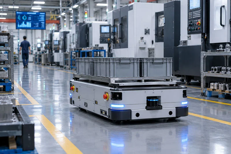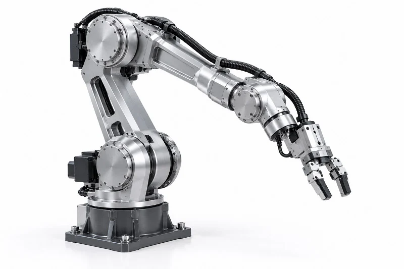
A robot arm’s performance depends on how its parts are made, not just on design intent. Robot arm components include the controller, sensors, joints, actuators, end effectors, and structural housings. Each one plays a specific role. So how do function, manufacturing processes, precision, and material choice connect in real projects? That link matters to engineers, product managers, and technical buyers. It shapes repeatability, payload, unit cost, lead time, and sourcing risk. This article moves from component categories to processes, then to materials, and ends with a practical selection framework you can apply.
Common Robot Arm Components and Functions
Controller, Sensors, and Actuators
Controller and safety coordination
The controller works like the brain of the system. It reads sensor data, runs motion algorithms, and sends commands to every joint. Safety coordination also happens here. The controller checks for faults, limits torque, and starts emergency stops when something goes wrong.
Torque, force, and vision sensors
Sensors give the arm its awareness. Torque sensors measure rotational force at each joint. Force sensors detect contact pressure at the wrist. Vision sensors help the arm find and inspect parts. These feedback loops keep motion accurate and stop damage.
Servo motors and actuator types
Actuators turn energy into motion. Electric servo motors lead in modern designs. Pneumatic actuators use compressed air for fast, simple movements. Hydraulic actuators handle very heavy loads. Each type fits different payload and speed needs.
Joints, Reduction Gears, and Encoders
Joint types and degrees of freedom
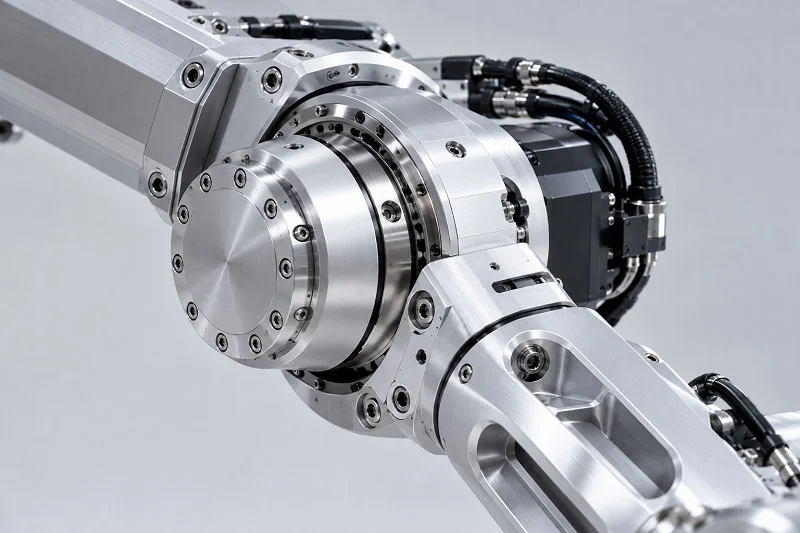
Joints decide how the arm moves. Rotary joints allow twisting motion. Prismatic joints give linear travel. Each joint adds a degree of freedom. A six-axis arm can reach almost any point in its workspace.
Reduction gear and transmission roles
Reduction gears multiply motor torque and cut speed. They sit between the motor and the joint. Gearboxes, belts, and harmonic drives are common choices. Backlash in these parts directly affects positioning accuracy.
Encoder feedback and positioning
Encoders track joint position in real time. They send pulses or digital signals to the controller. High-resolution encoders allow fine positioning. Without them, the controller cannot close the loop.
End Effectors and Structural Housings
End-of-arm tooling and grippers
End effectors do the real work. Grippers, suction cups, and welding torches are common examples. Gripper choice affects cycle time and reliability. Electric grippers often pass 10,000 operating hours. Pneumatic grippers need seal replacements every 3-6 months in humid or dusty places. One compressor failure can stop dozens of pneumatic actuators at once. Electric units fail one at a time and offer self-diagnostics for predictive maintenance.
Base, link, and housing structures
The base holds the arm to a surface. Robot arm links connect joints and carry loads. Robotic link bodies must balance stiffness and weight. Robotic arm link bodies often use aluminum or carbon fiber. Robotic actuator housings protect motors and gears from dust and moisture. Actuator housings also give mounting points for sensors. High-precision actuators depend on rigid housings to hold alignment. Structural link bodies and robotic actuator housings form the mechanical backbone of any robot arm components set.
Robot Arm Components Manufacturing Processes
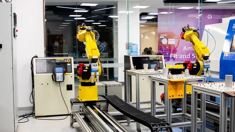
Every manufacturing process has good points. Picking the right one for each part is the key to making robot arm components. CNC machining takes care of most structural pieces. Sheet metal and die casting are great for covers. Injection molding works well for parts that don’t carry loads. Additive manufacturing is helpful for prototypes. The materials you choose also change which process you use. When the part and process match well, you save time and money.
CNC Machining for Robot Arm Components
Milling and turning of links and housings
CNC machining cuts material away from a solid block. Milling shapes flat surfaces, slots, and holes. Turning makes round features on shafts and housings. Most structural link bodies begin as aluminum blocks. These main structural link bodies carry heavy loads. The robotic arm structural components must be very stiff. Actuator housings also depend on CNC machining for exact alignment. This process gives tight control over every measurement. A machined part can match the design within a few hundredths of a millimeter.
CNC machining is great for low to medium volumes. For one to several thousand parts a year, it gives the best mix of quality and cost. Robotic link bodies and joint housings are common jobs.
Tolerancias y acabados superficiales
Tolerances really matter in robot arm components. A loose fit in one joint creates errors that spread through the whole arm. Here are typical ranges for CNC machined parts:
| Categoría de tolerancia | Tolerancia alcanzable | Aplicación típica |
| Estándar | ±0.125 mm (±0.005″) | Enclosures and brackets (ISO2768-m) |
| Precisión | ±0.01 mm (±0.0005″) | Bearing seats, alignment pins, interfaces |
| Rectificado de precisión | ±0.005 mm (±0.0002″) | Extreme precision (custom limits) |
Precision keeps tight tolerances on critical features. Parallelism between bearing bores on a link must stay under 0.02 mm. Misalignment past that point causes friction and early failure. Concentricity between joint interfaces cannot be compromised. Errors build up through the kinematic chain and cause big inaccuracies at the hand.
Surface finish matters just as much. Bearing seats need Ra 0.4 to 0.8 micrometers. A rougher surface increases wear. A profilometer measures these values during production. Actuator housings often get the same treatment. Smooth surfaces keep seals working and stop leaks.
Sheet Metal and Die Casting Processes
Covers, brackets, and mounting plates
Sheet metal parts protect internal components and provide mounting points. Robot covers, cable guides, and sensor brackets are common examples. Stamping presses cut and form sheets quickly. Each part takes 1 to 5 seconds. Tooling costs range from $10,000 to $100,000. Tolerances fall between ±0.1 and ±0.5 mm. Surface finish is good but not as smooth as machined parts.
High-volume housing production
Die casting works for large production runs. Molten aluminum gets injected into a steel mold under pressure. Wall thickness ranges from 1.5 to 4.0 mm. The minimum is about 1.0 mm. Thinner walls risk incomplete fill. Die casting reaches tolerances of ±0.1 mm. Surface finish measures 1.6 to 3.2 micrometers Ra. Part complexity can be very high. Each cycle takes 30 to 120 seconds. Tooling costs run from $15,000 to over $200,000. That makes the process best for 10,000 parts or more per year. Material waste is low at 5 to 10 percent.
From a practical view, die casting suits robot base housings and large covers. The process adds strength through thin ribs and bosses. No extra machining is needed for most surfaces.
Moldeo por inyección y fabricación aditiva
Plastic covers and non-structural parts
Injection molding shapes plastic into complex parts quickly. Non-structural covers, cable clips, and sensor housings are typical uses. Cycle times can be under 30 seconds. Tooling costs are high, but per-part cost drops fast at high volumes. Shrinkage during cooling must be accounted for in the mold design.
DMLS for metal prototypes
Direct metal laser sintering builds parts layer by layer from metal powder. No tooling is needed. That makes it ideal for prototypes and short runs. A new link design can be tested in days instead of weeks. DMLS handles complex internal features that milling cannot reach. Surface finish is rougher than machined parts, typically Ra 6 to 10 micrometers. Post-machining of critical surfaces is common. The process works best for one to fifty parts. Per-part cost is high, but the time savings often justify it. CNC machining still leads for production volumes of structural parts.
Design Considerations for Robot Arm Components
Tolerance Stack-Up and Joint Alignment
Process precision and repeatability
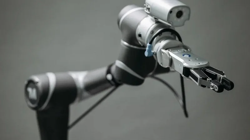
Each joint adds a small error to the system. These errors build up through the kinematic chain. A loose fit at joint one makes a bigger position error at the end effector. That is why tight tolerances matter on every critical feature. Bearing bores on a link body must stay parallel within 0.02 mm. Anything more than that causes friction and wear. If one link body sits at the high end of the tolerance band and the next at the low end, joint alignment shifts.
Repeatability depends on process precision. CNC machining holds ±0.01 mm on alignment pins and bearing seats. That level of precision components gives predictable assembly. Designers must plan for stack-up during the drawing phase.
Datum strategy and assembly fit
A good datum strategy ties machining, inspection, and assembly to the same reference frame. For robotics, datums should match how the robot is assembled and held in real use. The base mounting surface and dowel pins often become primary datums. Joint faces and bearing bores build from those references.
Here are best practices for datum selection:
| Buenas prácticas | How it affects assembly precision |
| Anchor datums to match real assembly conditions | All frames share the same reference |
| Use base mounting surface and dowel pins as primary datums | Functional features share one reference |
| Define clear datum surfaces and locating features | Repeatable positioning during assembly |
| Use dowel pins or machined shoulders for alignment | Components self-locate into position |
This approach gives precision assembly. Joint alignment stays consistent from unit to unit.
Weight, Stiffness, and Payload
Stiffness-to-mass trade-offs
A link must be stiff but light. Every gram away from the joint adds inertia and bearing load. Reducing mass helps the whole system. Here is how two common materials compare:
| Material | Resistencia a la tracción (MPa) | Densidad (g / cm³) | Fuerza específica |
| Compuesto de fibra de carbono | 600-1500 | 1.5-1.8 | 400-1000 |
| Aluminio 6061-T6 | ~ 310 | 2.70 | ~ 115 |
Carbon fiber gives 3 to 8 times higher specific strength than aluminum. A hybrid CFRP/aluminum prototype achieved a 24.32% mass reduction versus an aluminum design. That freed up payload capacity. The material and geometry choices you make directly affect payload.
Wall thickness and rib design
Ribs add stiffness without much weight. A hollow extrusion with internal ribs can match a solid bar’s stiffness at half the weight.
Designers should model the load path carefully. Add material only where it carries load. This approach saves weight without losing stiffness.
Acabado superficial y desgaste
Bearing seats and sealing surfaces
Surface finish on a robotic arm component joint affects wear life. Bearing seats need Ra 0.4 to 0.8 micrometers. Rougher finishes increase friction and shorten bearing life. Sealing surfaces also need smooth finishes.
Every bearing seat needs a surface finish callout on the drawing. Tight tolerances and smooth surfaces go together for long service life. A profilometer checks these values during production.
Coating and anodizing choices
Aluminum parts need surface protection. Anodizing is the standard choice for robot arm components. Parts that slide or rotate need uniform layers to avoid wear.
| Tipo de anodizado | Proceso | Espesor típico (micras) |
| Tipo I | De cromo | 0.5 – 2.5 |
| Tipo II | Sulfúrico | 5 – 25 |
| Tipo III | capa dura | 25 – 150 |
For bearing seats and joint interfaces, Type III hardcoat gives the best wear resistance. Hardness reaches 60-70 HRC equivalent. Coating thickness is typically 0.002 inches on functional surfaces. All final dimensions apply after coating. Impregnation with PTFE lubricant after anodizing adds extra life.
Common Materials for Robot Arm Components
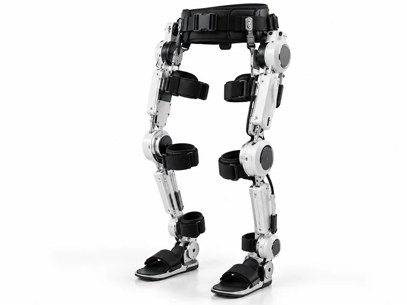
Choosing the right material for robot arm parts is like a balancing act. You need strength, low weight, and a cost that does not worry the finance team. The choice also affects which manufacturing process works best. Let’s look at the main types of robotics materials: plastics, metals, and composites.
Metals for Robot Arm Components
Aluminio 6061-T6 y 7075-T6
Aluminum is the main material for robot arm parts. Grade 6061-T6 has a good balance of strength, rust resistance, and ease of machining. It welds well and costs less than most other choices. Grade 7075-T6 is stronger, almost as strong as some steels. It is easy to machine but costs more and does not weld well. Both grades work well for CNC machining of link bodies and actuator housings. Aluminum alloy housings weigh 40-50% less than cast iron, but they do not spread heat as well. That weight savings directly increases payload capacity.
17-4 PH stainless steel and Ti-6Al-4V
Stainless steel and titanium are used when aluminum is not strong enough. Grade 17-4 PH has high strength and good rust resistance. It works well for shafts, pins, and high-stress joints. Titanium Ti-6Al-4V gives a very good strength-to-weight ratio. Using titanium only in high-stress pinion shafts reduces weight while keeping strength. Both materials need slower CNC cutting speeds and better cutting tools. They cost more, so designers use them only when necessary.
Plásticos y polímeros de ingeniería
POM, PEEK, nylon, and ABS
Plastics are used for covers, bushings, and parts that do not carry loads. POM (acetal) is easy to machine and keeps precise measurements. PEEK resists high temperatures and chemicals. Nylon is strong and does not wear out quickly. ABS is low cost and easy to shape. Each type works in different places of a robot arm. POM has a very low water absorption rate, usually less than 0.2%. This helps it keep exact sizes even in damp places. That makes it good for precise parts in robot arm covers.
Resistencia al desgaste y estabilidad dimensional
Moisture changes how plastics behave. Here is a quick look at how common robotics materials handle humid settings:
| Plástico | How Humidity Affects Size |
| POM | Little effect from water; temperature change matters more |
| Nailon | Absorbs water, which changes size and properties |
| OJEADA | Keeps size well; absorbs very little water |
| ABS | Affected more by heat than water; medium stiffness |
PEEK has a water absorption rate below 0.1%. This gives it excellent size stability in damp places. For robot arm covers, PC/ABS alloys are also used. But PEEK has better stability because it absorbs little water. Nylon absorbs more water and can change size. So it works for less important parts.
Composites and Hybrid Choices
Carbon fiber reinforced parts
Carbon fiber reinforced plastic (CFRP) gives the highest strength for its weight among common robotics materials. A hybrid CFRP/aluminum prototype cut mass by 24.32% compared to an aluminum design. That increased payload capacity. Carbon fiber reinforced nylon is self-lubricating and light. This makes it a good choice for low-load joints, especially at J6 where movement load is small. CFRP parts usually need special layup and curing, not standard CNC machining.
When composites justify the cost
Composites cost more than metals at first. Tooling and labor make the price higher. They make sense when saving weight improves performance. High-speed arms and collaborative robots benefit most. Topology optimization software finds designs that use less material but keep stiffness. Careful bearing selection also helps. Angular contact bearings made for the exact load remove the need for oversized parts. For a bearing seat or joint interface, the material and process must work together. A composite link with a machined aluminum insert often gives the best of both sides.
The biggest mistake we see in connecting cables on cobots is treating it like a regular robot cable bundle. Cobots have force and torque sensors in every joint. A cable that is too stiff, too heavy, or placed too tightly will create extra loads that cause safety stops — or worse, hide real crash events. You need cables built for the cobot’s movement, not just its electrical needs.
From a practical view, picking the material decides the process. Aluminum and steel work for CNC machining. Plastics are good for injection molding. Composites need their own special methods. Match the material to the part’s job, and the rest works out.
Matching Processes and Materials to Robot Arm Components

Choosing the right process and material combo depends on three things: volume, tolerance, and where the arm will work. Get these right, and everything else falls into place.
Selection by Volume and Tolerance
Low-volume, high-precision prototypes
For one-off builds or small batches, cnc machining is the best choice. There are no tooling costs, turnaround is fast, and you can hit tight tolerances on critical features. A prototype link body machined from 6061-T6 aluminum lets you test fit and function in days. Design changes stay cheap because you just edit the program. This approach works well for proof-of-concept arms and custom end effectors where precision matters more than unit price.
Producción de gran volumen y sensible a los costos
Once volumes go past several thousand units a year, die casting and injection molding take over. Tooling costs are high upfront, but per-part cost drops fast. A die-cast actuator housing reaches tolerances of plus or minus 0.1 mm and needs little finishing. The trade-off is clear: you commit to a design, and changes get expensive. For consumer robots or mass-market cobots, this path keeps unit costs low.
Selection by Application Environment
Collaborative versus industrial robots
Cobots prioritize lightweight materials and rounded shapes for safety. Carbon fiber links and plastic covers reduce inertia and limit impact forces. Industrial arms focus on stiffness and payload, so aluminum and steel dominate. The manufacturing process follows the material: cnc machining for metal links, injection molding for cobot shells.
Cleanroom, food-grade, and harsh settings
Food processing demands specific choices. Here is what hygienic design requires:
| Categoría de requisito | Especificación |
| IP rating for washdown | IP69K — withstands 100 bar (1,450 PSI) water jets at 80°C (176°F) |
| Material preferido | 316L stainless steel (Molybdenum content resists pitting from chlorine-based sanitizers; 304 is discouraged) |
| Rugosidad de la superficie | Ra ≤ 0.8 µm on food-contact and splash-zone surfaces |
| Design prohibitions | No exposed threads, no blind holes, no pooling ledges, no cable-tie traps |
| Governing guideline | Directriz EHEDG 62 |
For dairy and liquid food processing — where high-frequency hot water washdowns, caustic CIP chemical exposure, and zero tolerance for residue accumulation apply — SS316 construction with IP65 or IP67 ratings is stated as the minimum specification for manipulators used in direct dairy production areas.
KUKA HM robots follow EHEDG design guidelines and allow direct contact with foodstuffs. They use corrosion-resistant housings, food-grade lubricants, and stainless steel components. The KR DELTA HM is made entirely of stainless steel. Cleaning-sensitive electrical interfaces sit below the machine, away from the contact area.
Cost, Lead Time, and Quality Control
Tooling investment versus unit cost
Tooling is a bet on volume. Die casting tooling runs from $15,000 to over $200,000. Injection molding tools cost about the same. You need 10,000 parts or more per year to justify that spend. Below that threshold, cnc machining stays cheaper overall. Lead time also shifts: tooling takes weeks to build, while machined parts ship in days.
Inspection methods and traceability
Quality control in manufacturing robotic arm components relies on the right tools. A profilometer checks surface finish on bearing seats. CMMs verify hole positions and parallelism. For food-grade parts, documentation must trace material certs and surface roughness values. Every batch needs inspection records that tie back to the raw stock. This traceability protects both the builder and the end user.
NOBLE: Partner for Robot Arm Components Manufacturing
NOBLE focuses on metal and plastic machining for robot builders. The company helps with robotic arm component manufacturing from early design to final assembly. Engineers get a partner who knows how function, process, and material work together.
Experiencia en mecanizado de metales y plásticos
CNC machining and plastic fabrication
NOBLE does cnc machining for structural parts like link bodies and actuator housings. Aluminum, stainless steel, and titanium are common jobs. Plastic fabrication covers covers, bushings, and non-structural parts. POM, PEEK, and nylon all get machined to tight precision. The shop handles both metal and plastic in one place. That saves time and keeps tolerances the same across parts.
Soporte de prototipo a producción
A new arm design often starts with one or two units. NOBLE machines prototypes fast so you can test fit and function. Once the design is locked in, production grows without changing shops. Low-volume runs stay on cnc machining. Higher volumes move to casting or molding when it makes sense. You get a smooth path from first article to full production.
Certificaciones y Sistemas de Calidad
ISO 9001: 2015 e ISO 13485: 2016
NOBLE holds ISO 9001:2015 and ISO 13485:2016 certifications. The second one matters for medical robotics. ISO 13485 adds traceability rules that go beyond standard quality systems. Every lot ties to a mill heat number. Operator and inspector IDs get recorded at each step. Risk management follows ISO 14971, with written assessment before machining starts. Critical dimensions need capability indices of at least 1.33 in ongoing production. Process validation covers special steps like titanium stress relief. Any change to an insert grade or machine needs an engineering change request and quality manager approval. That adds one to three days but stops process drift between lots.
Inspección y documentación
Quality control uses CMMs, profilometers, and first-article inspection. Every batch gets records that tie back to raw stock. For medical parts, Device History Records track components down to single pieces. Post-market surveillance and complaint handling follow formal procedures. Cleanliness specs are written down for parts that touch patients or sterile fields.
Diseño y montaje con servicio integral
Diseño para el apoyo a la fabricación
NOBLE engineers review drawings before cutting metal. They flag features that are hard to machine or inspect. Wall thickness, rib design, and datum strategy all get checked. This feedback saves cost and avoids rework later.
Assembly, testing, and fulfillment
NOBLE does more than production. The team handles assembly, testing, and fulfillment. Sub-assemblies arrive ready to install. Functional tests check joint alignment and actuator fit. Final packaging and shipping complete the service. You get one partner from design to delivery.
What a part does shapes the process you pick. The process you pick sets the precision you can really hold. Then precision needs cut down your material choices. That chain runs through every robot arm components project, and no single process or material wins every time. Volume, tolerance, application environment, and cost targets decide the answer. So take the selection framework and test it on your own build. Where does your arm work? What repeatability do you need? How many units will you make? Bring those answers to NOBLE’s engineering team or ask for a quote. You get design-to-assembly support and certified quality systems behind every part.
FAQ of Robot Arm Components
What tolerance can CNC machining hold on robot arm components?
Standard CNC work holds about ±0.125 mm. Precision features like bearing seats and alignment pins reach ±0.01 mm. Precision grinding pushes that to ±0.005 mm. Those tight numbers matter because small errors stack up through the kinematic chain and show up as position error at the hand.
Why does backlash in reduction gears hurt accuracy?
Backlash is lost motion between the motor and the joint. The controller commands a move, but the joint lags until the slack closes. That delay shows up as positioning error. Harmonic drives and preloaded gearboxes cut backlash, so robot arm components stay repeatable over millions of cycles.
When should I pick die casting over CNC machining?
Die casting wins past roughly 10,000 parts a year. Tooling runs from $15,000 to over $200,000, but per-part cost drops fast. Tolerances land near ±0.1 mm with little finishing needed. Below that volume, CNC machining stays cheaper and lets you change the design without new tooling.
Is carbon fiber worth the cost for a robot arm link?
It depends on the payoff. Carbon fiber reinforced plastic gives 3 to 8 times higher specific strength than aluminum. One hybrid CFRP/aluminum prototype cut mass by 24.32%. That extra payload capacity often justifies the price on high-speed arms and cobots, where lower inertia means faster, safer motion.
What surface finish do bearing seats need?
Bearing seats should sit between Ra 0.4 and 0.8 micrometers. Rougher surfaces raise friction and shorten bearing life. Sealing surfaces need the same care. A profilometer checks these values during production, so every batch matches the drawing callout.
Which anodizing type works best for joint interfaces?
Type III hardcoat anodizing gives the best wear resistance for bearing seats and joint interfaces. It reaches 60-70 HRC equivalent hardness with a 25 to 150 micron layer. Type II sulfuric anodizing suits general aluminum parts. Final dimensions apply after coating, so plan the allowance upfront.
How do I choose materials for a food-grade robot arm?
Go with 316L stainless steel and an IP69K rating. Surfaces should stay at Ra ≤ 0.8 µm on food-contact zones. Avoid exposed threads, blind holes, and pooling ledges. EHEDG Guideline 62 covers the design rules, and KUKA’s HM line follows them for direct food contact.
What certifications should a robot arm components supplier hold?
Look for ISO 9001:2015 as the baseline. Medical robotics needs ISO 13485:2016, which adds lot traceability back to mill heat numbers and capability indices of at least 1.33 on critical dimensions. Ask for first-article inspection records and CMM reports before you commit to production.