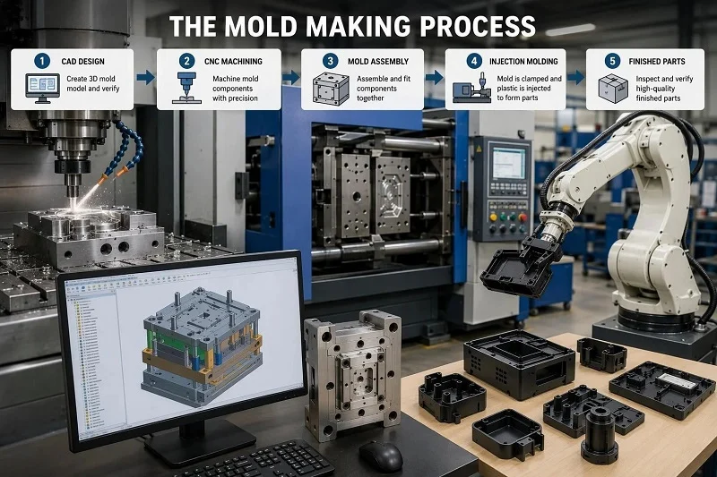
A plastic mold is the tool that turns molten resin into a finished part: the cavity and core define the shape, the feed system delivers the melt, the cooling circuit sets the cycle, and the ejection system releases the part intact. Getting a mold that produces dimensionally accurate, cosmetically acceptable parts at your target volume is not a single decision but a sequence of them — and each one constrains the next.
This guide follows that sequence. It starts with the inputs a plastic mold project needs before any geometry is drawn, walks through the six stages from design review to first-article qualification, then drills into the two areas where projects most often go wrong: choosing the material the mold itself is made from, and the design points inside the plastic mold that decide whether parts come out right. It closes with the recurring mistakes worth auditing against your own plan, and with how a manufacturing partner fits into the picture.
ما تحتاجه قبل أن تبدأ
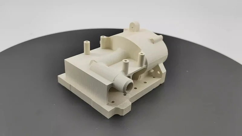
A plastic mold project cannot start in earnest until a small set of inputs is fixed. Each one is an engineering input that changes tooling geometry, not paperwork to be gathered later.
A finalized 3D part نموذج in a usable CAD format (STEP, IGES, Parasolid or native) is the base geometry. Without it, no cavity can be cut and no manufacturability review can run.
The chosen resin, with its shrinkage and wall-thickness behavior. Shrinkage data drives cavity dimensions; the resin’s recommended wall range drives whether the part can be molded at all. Locking the grade early prevents the cavity from being cut for the wrong allowance.
Production volume and target cycle time. Volume sets cavity count, mold material and the wear resistance you need. Target cycle time sets how much cooling capacity the plastic mold must carry.
The press the plastic mold must fit. Tonnage, tie-bar spacing and platen size cap the mold’s footprint and its projected area. A mold that exceeds the available press cannot run, regardless of how well it is designed.
Required tolerances and surface finish. These determine machining, polishing and texturing effort, and they determine whether the tolerance you have written is achievable in the molding process at all.
الميزانية والجدول الزمني. These decide where the trade-offs land — for example, whether a hot runner is justified or whether a single-cavity tool is the right first investment.
If any of these is still open, resolve it before tooling starts. The cost of changing a resin or a wall thickness after the cavity is cut is far higher than the cost of deciding it now.
The Plastic Mold Workflow: From Design to Production
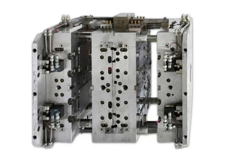
The workflow below is ordered. Each stage produces something the next stage depends on, and each has a checkpoint that confirms it is finished before the next begins.
Step 1 — Review the Part Design for Moldability
Before any tooling geometry is drawn, run a design-for-manufacturability review on the part model. Inspect wall thickness consistency across the part, draft on every vertical face, undercuts and whether they can be avoided or will need side actions, corner radii, and the proportions of bosses and ribs relative to adjacent walls. Confirm where the gate and ejectors can land and where the parting line will sit.
The outcome is a marked-up model and a list of part changes — or, where a change is not acceptable, a documented decision to accept the cost of side actions. Either is a valid result; an unreviewed model is not.
نقطة تفتيش: every wall and feature has been checked against the chosen resin’s recommended thickness range, and every vertical face carries draft.
Step 2 — Confirm Material and Shrinkage
Lock the resin and pull its shrinkage rate before cavity dimensions are set. The cavity and core are cut oversize by the shrinkage allowance, so the part that comes out of the tool matches the drawing. Shrinkage varies by resin and by direction relative to flow, and glass- or fiber-filled grades behave differently from unfilled ones — often shrinking less along the flow direction than across it.
Take the shrinkage figure from the resin supplier’s data for the specific grade rather than from a generic table. Two grades in the same family can carry different allowances, and a generic number applied to a filled grade will produce a part that is out of tolerance in one direction.
نقطة تفتيش: the shrinkage value is recorded against the exact grade and has been applied to the cavity model.
Step 3 — Design the Mold: Cavity Layout, Feed System, Cooling and Ejection
Build the plastic mold assembly around the part, making the decisions in sequence.
- Cavity count and layout. Balance the number of cavities against annual volume and press capacity, then lay them out so the melt reaches each cavity under the same conditions.
- Runner type and gate. Choose a cold or hot runner, then select gate type, size and location. The gate controls fill, packing and how visible the gate mark will be on the finished part.
- Route the cooling channels to remove heat evenly from the part. Cooling design drives cycle time and has a direct effect on warpage.
- Choose the ejection method and decide where ejector marks will land — ideally on a non-cosmetic surface.
- Place vents at the parting line and at the end of fill, where air is last to escape.
نقطة تفتيش: a mold flow or fill analysis has confirmed balanced fill, no short shots, and acceptable weld-line and air-trap locations.
Step 4 — Detail and Tolerance the Mold Components
Convert the assembly into manufacturable drawings. This covers the mold base and plate stack-up, guide pins and bushings, slides and lifters for any undercuts, inserts, and the tolerance stack between cavity, core and parting surfaces.
Fits and clearances must account for thermal expansion at operating temperature, not just at room temperature. A clearance that is comfortable on the bench can close up when the mold reaches its running temperature.
نقطة تفتيش: the drawing set is complete enough that a machinist can cut every component without coming back with a design question.
Step 5 — Machine, نهاية and Assemble the Mold
Cut the mold material, then finish and fit it. Rough and finish machine the cavity and core; use EDM for deep ribs and sharp internal corners that a cutter cannot reach; polish to the specified surface grade; and hand-fit slides, lifters and inserts.
The machining sequence matters for stress relief in the plate. Removing large amounts of material in one pass can release residual stress and distort the plate, so rough machining, a rest period and finish machining are often sequenced deliberately.
نقطة تفتيش: all components are dimensioned against the drawing and the assembly moves freely by hand before it goes to the press.
Step 6 — Trial the Mold and Qualify the Parts
Run the first shots and use them to close out the project. A trial establishes fill balance, cycle time, dimensional conformance, cosmetic quality and ejection reliability. Use the results: adjust gate size, cooling or venting, then re-run.
Take dimensional reports on parts from a stable, production-representative cycle rather than the first few shots. Early shots are still settling, and measuring them can send you chasing a problem that does not exist in production.
نقطة تفتيش: a first-article inspection report shows the parts inside tolerance across the full cavity set, and the plastic mold runs a stable cycle.
Choosing Mold Materials for a Plastic Mold
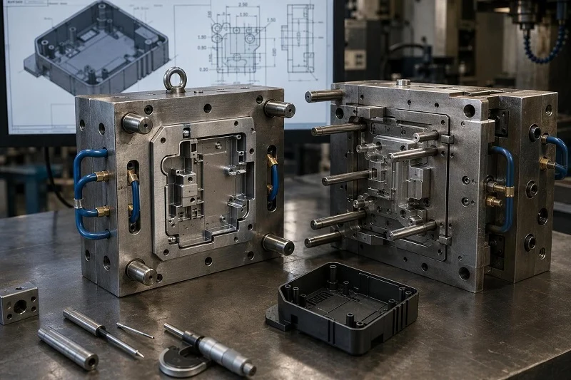
The material of the mold itself is a separate decision from the resin it will mold, and it is a balance rather than a single best choice. The relevant properties are thermal conductivity, hardness and wear resistance, machinability, corrosion behavior and cost — and the right balance depends on volume, resin and part requirements.
الامونيوم المواد العفن
Aluminum fits low-to-medium volume and large parts. It has good thermal conductivity for fast cycles, machines quickly and easily, and costs less than steel for the same block. Within aluminum, distinguish high-strength wrought mold plate from medium-strength wrought plate and from cast tooling plate: the high-strength grades carry much higher hardness and strength, while cast plate offers very low internal stress and good stability for flat, large molds.
One practical caution: in quench-sensitive alloys, strength and hardness vary through the thickness of a thick section, which affects stability during machining. Alloys developed with low quench sensitivity hold more uniform properties through the plate and machine more predictably.
Aluminum is also more susceptible to corrosion in cooling channels than steel. Water chemistry and dissimilar-metal contact need attention — keep the water near neutral and isolate fittings where two different metals meet.
Copper Alloy Mold Materials
Copper alloys fit hot spots, thick sections and cycle-time-critical areas, where their very high thermal conductivity removes heat faster than aluminum or steel can. They can be used for entire molds or as inserts in a steel or aluminum body.
The available hardness range is wide — from roughly 20 Rc up to about 40 Rc depending on the alloy — and the softer grades polish well but wear faster. Polishing behavior is generally good, which suits optical and cosmetic surfaces.
A practical point: a copper insert in an aluminum body needs a barrier coating where a water channel passes through both, such as electroless nickel on the back of the copper, to avoid galvanic corrosion between the two alloys.
Tool Steel Mold Materials
Steel fits high-volume runs, abrasive or glass-filled resins, and tight-tolerance parts. It offers high hardness and wear resistance, which is what keeps cavity dimensions stable over hundreds of thousands of cycles.
Distinguish pre-hardened grades — which machine and go straight into service at roughly 30 Rc — from grades that are hardened after machining to 50 Rc and above. Hardness trades against machinability and thermal conductivity: a harder plastic mold lasts longer but cuts more slowly and removes heat less readily than aluminum.
Matching the Material to Volume, Resin and Part Requirements
Apply the families through a short routine, in this order:
- كم عدد الأجزاء؟ حجم منخفض إلى متوسط points to aluminum; high volume points to steel.
- How abrasive is the resin? Glass- or fiber-filled grades wear a plastic mold quickly and favor steel, or hardened inserts at the gate and high-wear areas.
- ما مدى دقة التفاوتات المسموح بها؟ Tight tolerances favor the dimensional stability of steel.
- How critical is cycle time? Fast cycles favor aluminum, or copper inserts at hot spots.
- ما هو حجم القطعة؟ Large parts favor aluminum for cost and machinability.
- ماذا تسمح به الميزانية؟ The answer narrows the family; the specific grade follows from the same answers.
Note that prototype and bridge tooling and production tooling are different investments and should be specified separately. A tool built to validate a design is not automatically a tool built to run for years.
Plastic Mold Design Points That Decide Part Quality
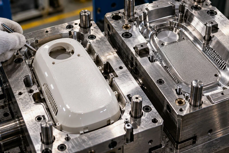
These are the design decisions inside the mold that most often determine whether the parts come out right. Each is stated as a point to get right, why it matters to the molded part, and what to specify.
سُمك الجدار ونسب الميزات
Walls should be as uniform as the part allows. Non-uniform walls drive sink, warp, internal stress and dimensional inaccuracy, because thick sections cool more slowly than thin ones and pull the part out of shape as they shrink.
Secondary features such as ribs and boss walls are commonly kept to roughly 40–60 percent of the adjacent wall to avoid sink. Recommended wall thickness ranges differ by resin — for example, ABS is commonly cited at about 0.045–0.140 in and polycarbonate at about 0.040–0.150 in — so check the part against the range for the chosen grade.
Where a section is too thick, core it out rather than leaving solid material, and use ribs or gussets instead of thickening walls. This preserves strength while reducing sink and cooling imbalance.
مشروع الزوايا والطرد
Every face parallel to the direction of mold opening needs draft. A common starting rule is about one degree per inch of cavity depth, and textured surfaces need more — a light texture may call for three degrees or more, and heavier textures more still.
Draft connects directly to ejection force, scuffing, and the internal stress that shows up later as warp or curl. Keep draft consistent across the part; a face that is drafted in one region and near-vertical in another will drag during ejection and leave marks.
Gates, Runners and Fill Balance
Gate type, size and location control fill, packing and the visibility of the gate mark. A gate that is too small restricts flow and forces higher injection pressure; a gate placed on a cosmetic surface leaves a mark that may not be acceptable.
In a multi-cavity layout, balance the feed so all cavities fill at the same time and pressure. Getting this wrong produces overpacking near the gate, short shots in far cavities, and weld lines in structurally loaded areas.
Cooling Channel Design and Cycle Time
Cooling typically dominates cycle time. Channel diameter, spacing and distance from the cavity surface set how fast heat leaves the part: channels too far from the surface cool slowly, and channels too close can create uneven cooling and stress.
In deep cores, use baffled or conformal cooling to reach areas a straight drilled channel cannot. Uneven cooling is a leading cause of warpage and dimensional drift, so cooling design is a quality decision as much as a speed decision.
Shrinkage, Tolerances and Warpage Control
The shrinkage allowance is applied to the cavity, and it varies by resin, direction and wall section. Tolerance on the plastic molded part must be realistic for the process rather than copied from a machined-part drawing; a tolerance that is routine on a CNC part may be outside what molding can hold across a full cavity set.
Warpage is usually a cooling-and-orientation problem. Address it in the plastic mold design — through cooling balance and gate location — rather than by tightening the tolerance after the fact.
Venting and Surface Finish
Air trapped ahead of the melt causes burns, short shots and high injection pressure. Vents belong at the parting line and at the end of fill, where the air is last to escape.
The specified surface finish on the part translates into polishing or texturing work on the cavity. A textured surface changes the draft requirement, so specify texture and draft together rather than adding texture after the mold is cut.
Common Mistakes When Making a Plastic Mold
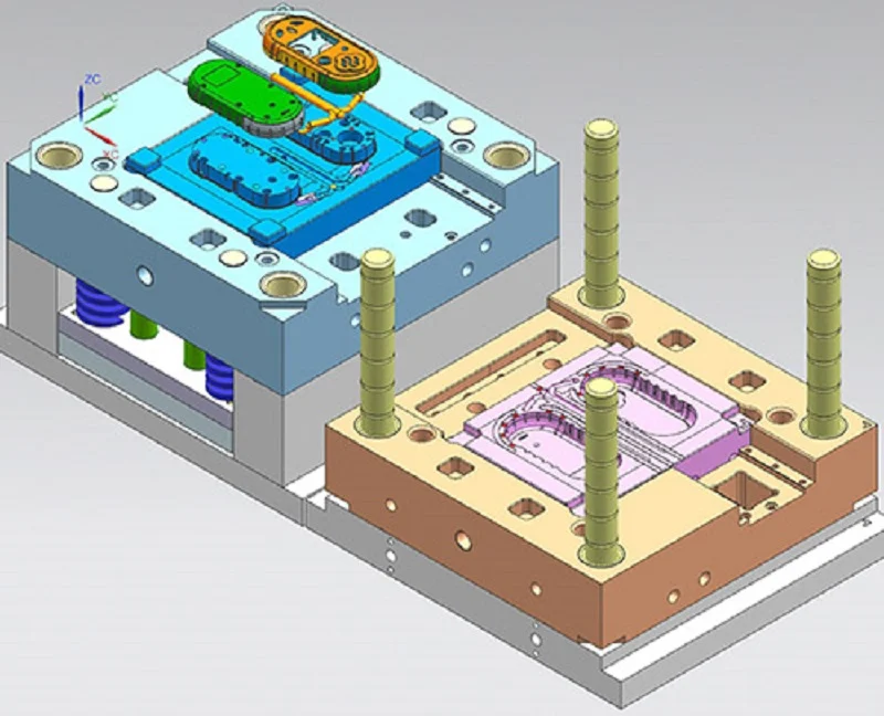
These failure modes recur across projects. Each is worth auditing against your own plan before tooling starts.
Designing the part without regard to draft or wall uniformity. The consequence is sink, warp and ejection damage that cannot be fixed by adjusting the press. The correction is a design-for-manufacturability review before any cavity geometry is drawn.
Choosing mold material before the volume and resin are known. The consequence is either an overbuilt tool that costs more than it needs to, or an underbuilt tool that wears out mid-run. The correction is to fix volume and resin first, then select the material family.
Skipping fill or cooling analysis on complex parts. The consequence is unbalanced fill, short shots and warpage discovered only at trial, when changes are expensive. The correction is a mold flow analysis before the design is released to machining.
Specifying machined-part tolerances on molded parts. The consequence is a part that is rejected against a tolerance the process cannot hold, even though the mold is correct. The correction is to set tolerances that reflect what molding can achieve for that resin and geometry.
Neglecting cooling water chemistry. The consequence is corrosion and blocked water lines, which slow cycles and eventually stop the mold. The correction is to keep water near neutral, avoid chlorinated biocides and isolate dissimilar metals.
Treating the first trial as the finish line. The consequence is a plastic mold that is released before it is stable, and production problems that surface later. The correction is to adjust and re-run until a first-article inspection passes across the full cavity set on a stable cycle.
Choosing NOBLE to Make Your Plastic Mold and Produce Your Parts

NOBLE is a contract manufacturer based in China, a Sino-British joint venture recognized by the government as a National High-tech Enterprise, with more than ten years of experience in parts machining, prototyping and manufacturing. We are certified to ISO 9001:2015 and ISO 13485:2016.
Our service capability and machining expertise are built to move a project efficiently from prototype through mass production. A complete RFQ receives a professional quote within 24 hours, prototypes can be turned around rapidly, and production support continues at volume. Our in-house capabilities cover design, prototypes and mass production of parts.
That matters for a mold project because the plastic mold and the parts it produces are one decision, not two. NOBLE provides a full service from design to assembly — not production alone: design-for-manufacturability analysis, mold making, machining, surface finishing and assembly, backed by in-house inspection equipment and an IQC, IPQC and FQC/OQC quality process. Our inspection equipment and overall quality control system are there to ensure your prototypes and components are created with high accuracy.
If you have a part model and a volume target, you can submit an RFQ for a quote and a manufacturability review. Upload your CAD files with the information needed, and our engineers will respond with design analysis and transparent pricing.
FAQs of Plastic Mold Making
How long does it take to make a plastic mold?
The schedule follows the stages rather than a single number. Simple molds move faster than molds with side actions or tight cosmetic requirements, and the trial-and-adjust loop adds time after machining. You can compress the schedule most by finalizing the part design and resin before tooling starts.
What drives the cost of a plastic mold?
The main cost drivers are the number of cavities, part size and complexity, undercuts and side actions, surface finish and texture, mold material, and tolerance requirements. Mold cost is a one-time investment amortized over the production run, so the cheapest mold is not always the lowest total cost.
How many cavities should my mold have?
Cavity count follows from annual volume, press capacity, and the cost of the mold versus the cost per part. A single-cavity tool is often the right starting point for low volume, or for validating the design before committing to a multi-cavity tool.
Can a prototype mold be used for production?
It can, for limited volumes and for resins and tolerances the tool was built to handle. But a tool built for prototyping may not have the hardness, cooling or cavitation for a full production run. Specify the intended volume up front so the tool is built for it.
What do I need to provide to get a plastic mold quote?
Provide a 3D part model, the resin, the annual and lifetime volume, tolerance and surface finish requirements, the target press if known, and the delivery date. A complete RFQ is what allows a fast and accurate quote.
Should I choose aluminum or steel for my plastic mold?
Aluminum suits faster cycles, lower tooling cost and low-to-medium volume; steel suits high volume, abrasive resins and tight tolerances. Let the volume and resin drive the decision rather than making it first.