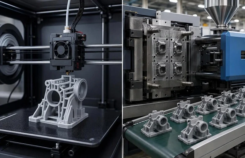
A plastic part rarely moves from a CAD file to a shipping carton in one step. Somewhere between the first design review and the ten-thousandth unit, someone has to decide how the part will actually be made — and for most plastic components the shortlist comes down to 3D printing vs injection molding. Framing that choice as a contest between an advanced method and a traditional one misleads. The two processes carry different cost structures, obey different geometry rules, and are judged against different quality expectations. One charges you for machine time; the other charges you for a tool.
This comparison works through the criteria that decide the route: how each process physically forms a part, what that means for lead time, where the unit-cost curves cross, which geometries each permits, what materials and tolerances you can expect, and which applications each fits. It closes with a decision rule you can apply to your own part — and with the note that the crossover point is specific to your geometry, material and volume, not a fixed number borrowed from a general guide. NOBLE supports both paths, from prototype iterations to production tooling, so the comparison is written for teams that may need either.
مقارنة سريعة: الطباعة 3D Vs حقن صب في لمحة
The table below summarises the comparison at the level published process data supports. Treat the figures as capability ranges and reference bands, not quotations for a specific part.
| معيار | الطباعة 3D | حقن صب |
| الأدوات المطلوبة | لا شيء؛ الملف الرقمي هو المدخل | Yes — aluminium, soft steel or hardened steel mold cut before any saleable part exists |
| المدة الزمنية النموذجية لتوريد الأجزاء الأولى | Hours to days, including post-processing | Tool fabrication of roughly 2–4 weeks (aluminium prototype mold), 4–8 weeks (soft steel or bridge mold) or 8–20 weeks (full production steel mold), then trial shots and qualification |
| Unit cost behaviour | Comparatively flat; each part consumes similar machine time | ينخفض الإنتاج بشكل حاد مع استهلاك تكلفة الأدوات لمرة واحدة على مدى حجم الإنتاج |
| Undercuts, internal channels, lattices | Built without draft or split lines; internal channels and lattice structures are routine | تتطلب التجاويف السفلية حركات جانبية أو رافعات أو نوى قابلة للتضحية؛ بعض الأشكال الهندسية الداخلية مستحيلة عمليًا في قالب صلب |
| Draft and wall uniformity | No draft requirement; orientation-dependent properties and support marks instead | Draft angles, uniform wall transitions and shrinkage compensation are design-time obligations |
| نطاق المواد | Process-specific: photopolymers, nylon powders, engineering filaments | مجموعة كاملة من اللدائن الحرارية المستخدمة في الإنتاج، بما في ذلك الدرجات المملوءة والهندسية. |
| التسامح النموذجي | تختلف نطاقات الطباعة المنشورة حسب العملية - FDM هي الأقل دقة بنسبة ±0.5% تقريبًا مع حد أدنى؛ SLA و PolyJet هما الأكثر دقة؛ SLS و MJF حوالي ±0.3% مع حد أدنى | Repeatable, taken from the tool; tight or cosmetic-critical surfaces may still need secondary operations |
| الانتهاء من السطح | تدرج الطبقات في تقنية FDM؛ ملمس حبيبي غير لامع في تقنيتي SLS وMJF؛ نعومة شبه مصبوبة في تقنيتي SLA وPolyJet | Replicates the tool surface consistently across the run |
| الأحجام الأنسب | النماذج الأولية، الكميات الصغيرة، الإنتاج الانتقالي، الأجزاء المصممة حسب الطلب | Stable designs at volume, where tooling amortises comfortably |
| التطبيقات الأنسب | Iteration, complex or consolidated geometry, patient-matched devices, jigs and fixtures | قطع الإنتاج التي تحتاج إلى مواد لدائن حرارية هندسية وتشطيب تجميلي متناسق |
One caution governs the whole table: the volume at which molding becomes the cheaper route depends on part size, material, tool complexity, cavitation and cosmetic requirements. Published crossover figures differ widely for exactly that reason, and the sections below explain why rather than offering a single universal number.
كيف تعمل الطباعة ثلاثية الأبعاد والقولبة بالحقن فعلياً
كل اختلاف في التكلفة والسرعة والهندسة في هذه المقالة لاحقاً ينبع من كيفية تشكيل العمليتين لجزء واحد فيزيائياً. إن توضيح هذه الميكانيكا أولاً يُبقي بقية المقارنة على أساسها الصحيح.
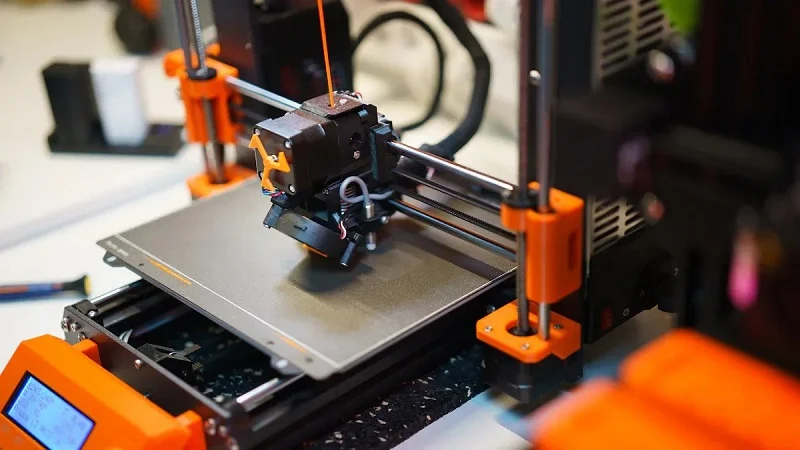
What Happens In 3D Printing
تقوم الطابعة ثلاثية الأبعاد ببناء مجسم عن طريق ترسيب أو دمج طبقات متتالية من المواد الخام، حيث تتصل كل طبقة جديدة بالطبقة التي تحتها حتى يكتمل المجسم. المدخلات عبارة عن ملف رقمي ثلاثي الأبعاد - نموذج CAD أو، في المجال الطبي، بيانات تصوير - ولا حاجة إلى قالب أو أداة تصنيع أخرى. هذا الغياب للأدوات هو ما يسمح بإجراء أي تغيير في التصميم عن طريق تعديل الملف بدلاً من تصنيع قطع مادية.
Build orientation matters more than newcomers expect. Orientation determines where support structures are needed, how stair-stepping appears on angled surfaces, and how the part’s properties distribute across axes. Support removal, curing and surface treatment are mandatory post-processing steps across additive processes, and they add time and labour to every build. Resolution and speed also trade off directly: thinner layers improve finish but lengthen the build, a constraint that holds across polymer and metal systems alike.
إنّ الطريقة الرئيسية التي تُحسّن بها الطباعة كفاءة الحجم هي تكثيف الطبقات. إذ تُمكّن أنظمة الطباعة بمسحوق المعادن من دمج العديد من الأجزاء في طبقة واحدة دون الحاجة إلى مواد داعمة، كما أنّ تكثيف الطبقة يُقلّل من استهلاك الطاقة لكل كيلوغرام مُرسب. هذه الفائدة حقيقية ولكنها محدودة، فهي تُحسّن اقتصاديات عملية الطباعة، وليس العلاقة الأساسية بين تكلفة الطباعة ووقت تشغيل الآلة لكل جزء.
What Happens In Injection Molding
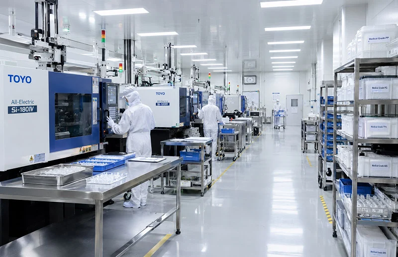
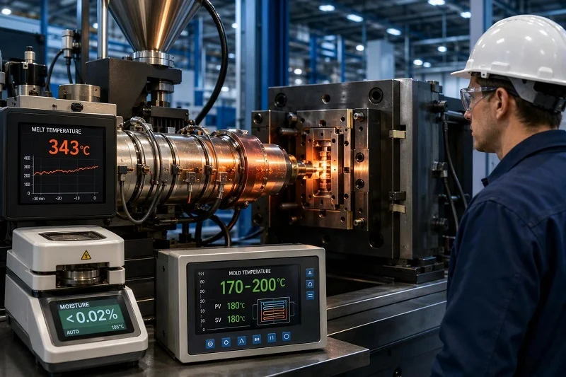
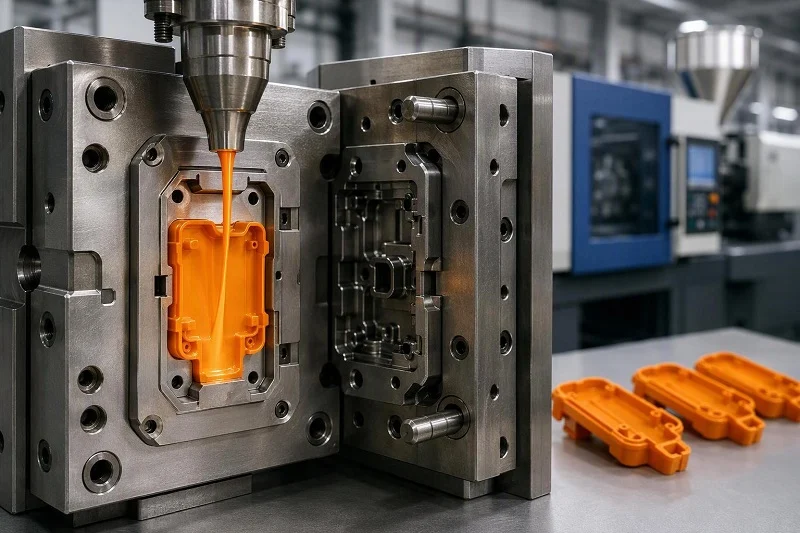
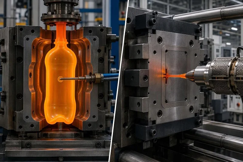
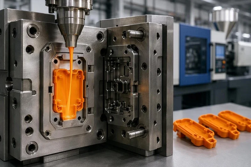
Injection molding fills a closed steel or aluminium mold cavity with molten polymer under high pressure. After the cavity is volumetrically filled, packing pressure is maintained to compensate for shrinkage as cooling begins, and the part then solidifies against the mold walls before ejection. Cooling typically represents the longest portion of the cycle.
من الأهمية بمكان تصميم الأداة وتصنيعها قبل إنتاج أول قطعة قابلة للبيع. هذا التسلسل هو مصدر وقت الإنتاج وتكلفة عملية التشكيل. كما يعني أن العيوب قد تنشأ من مصدرين مختلفين: بعضها متأصل في هندسة القالب قبل تصنيعه - مثل اختلاف سماكة الجدار، وموضع البوابة، وعدم توازن التبريد - بينما ينشأ البعض الآخر من عدم استقرار درجة الحرارة أو الضغط أو التوقيت في الماكينة، ويختلف من وردية عمل إلى أخرى أو من دفعة إلى أخرى. تتعامل البرامج المستقرة مع عملية التشكيل كنظام يتم التحكم فيه حراريًا وضغطًا، وليس مجرد خطوة تشكيل بسيطة؛ وعندما يتم تطبيق نظام التحكم، تحقق العملية تكرارًا استثنائيًا عبر عمليات الإنتاج الطويلة.
لماذا تُحرك الآليات الاقتصاد؟
لا تتطلب الطباعة تكلفةً للأدوات، لكنها تُغطي تكلفة وقت تشغيل الآلة لكل قطعة، لأن كل قطعة تشغل مساحةً في عملية التصنيع لفترةٍ متقاربة بغض النظر عن حجم الطلب. أما القولبة، فتعكس هذا الوضع: إذ تُتيح تكلفةٌ كبيرةٌ لمرةٍ واحدةٍ للأدوات دورةً قصيرةً تُنتج القطع بتكلفةٍ منخفضةٍ بمجرد توفر الأداة. لا شيء مما يلي في مناقشة حجم الإنتاج هو إلا نتيجةٌ لهذا الانعكاس - ولهذا السبب فإن القرار المكلف في مشروع القولبة هو قرار الأدوات، وليس خطوة القولبة نفسها.
مقارنة بين تدفق العمليات والوقت اللازم للتنفيذ
The sequence a project travels through differs as much as the physics. What each step costs in calendar time determines when you hold a part in your hand.
The 3D Printing Workflow: File To Part
The workflow runs from model preparation and orientation through build scheduling, printing and post-processing. Because there is no tool to fabricate, turnaround is measured in hours to days rather than weeks. Design changes between iterations cost only a new file and a new build — no hardware is scrapped. Post-processing is the step that most often surprises schedules: support removal, washing, UV curing and finishing are mandatory and consume labour, and in metal systems sintering, cooling and depowdering can add many hours beyond the print itself.
The Injection Molding Workflow: تزيين قبل الأجزاء
Molding runs through mold design, tool fabrication, trial shots and qualification before production begins. Published reference bands put an aluminium prototype mold at roughly 2–4 weeks to fabricate, a soft steel or bridge mold at 4–8 weeks, and a full production steel mold at 8–20 weeks — all before any parts can be produced. These bands vary with tool complexity and supplier capacity, and they sit outside any quoted production window rather than adding neatly to it.
التغييرات الهندسية التي تُجرى بعد تصنيع القالب هي التي تؤدي إلى تأخير جداول الإنتاج. التعديل ممكن ولكنه مكلف، وقد تؤدي المراجعات المعقدة إلى تأخير الجدول الزمني لأسابيع. لهذا السبب، فإن مراجعة التصميم قبل بدء تصنيع القالب تُعدّ استثمارًا مُجديًا: فاكتشاف المشكلة في الرسم أقل تكلفة بكثير من اكتشافها بعد تصنيع القالب.
الصوت وتكلفة الوحدة: نقطة التقاء الجوانب الاقتصادية
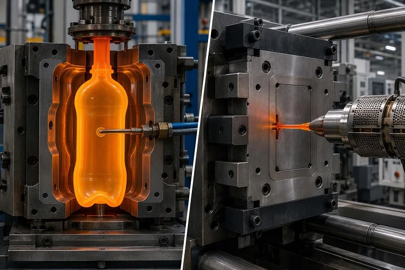
The cost comparison is not a single break-even figure but two curves with different shapes. Printing’s per-part cost stays comparatively flat; molding’s falls steeply as tooling amortises. Where they cross moves with the part.
لماذا تبقى تكلفة الوحدة المطبوعة ثابتة نسبيًا
Machine time, material and post-processing labour dominate printed cost, and each part consumes a similar share of all three regardless of order size. Published ranges put printed parts at roughly $5 to $200+ each depending on material, size and process. Packing a build improves efficiency, but mainly for powder-bed processes such as SLS and MJF; other processes gain far less from nesting. The practical consequence is that printing is almost always the cheaper total-cost route for very small quantities — commonly cited as roughly 1–100 parts — because there is no tooling to amortise.
Why Molded Unit Cost Falls With Volume
Tooling, not the per-part molding step, is the largest cost driver in a molding project. Amortising an aluminium mold costing roughly €3,000–€8,000 over a 100-part run works out to €30–€80 of tooling cost per part; amortising a full production steel mold at €15,000–€80,000+ over the same run works out to €150–€800 per part. That gap closes fast as volume rises, which is why matching tooling tier to real quantity matters more than defaulting to the longest-lasting option. Multi-cavity tools and short cycle times then compound the advantage, and for programs measured in tens or hundreds of thousands of units per year, molding delivers cost efficiency at scale that printing cannot match.
Finding Your Crossover
تختلف نقاط التعادل المنشورة اختلافًا كبيرًا لأنها تصف أجزاءً مختلفة. يشير أحد النطاقات الشائعة إلى أن نقطة التعادل تقع بين 500 و2,000 وحدة للأشكال الهندسية والمواد النموذجية. وجدت دراسة للتخصيص الشامل باستخدام مقياس الطاقة لكل جزء أن نقطة التعادل تتراوح بين 50 و300 جزء نموذجي اعتمادًا على مادة قالب الطباعة، مع الإشارة صراحةً إلى أن هذا الرقم خاص بهذا الجزء ومن المتوقع أن يختلف باختلاف الشكل الهندسي. في سباقٍ خاص بشركة مصنعة لطابعات الراتنج للوصول إلى 1,000 جزء، أفادت الشركة بأن نقطة التعادل تقع عند 13,050 جزءًا لمكون المزلاج الخاص بها. هذه ليست تناقضات؛ إنها أجزاء مختلفة، وأدوات مختلفة، ومقاييس مختلفة.
The practical method is to compare total project cost — tooling plus parts plus finishing plus likely engineering changes — at your realistic volume, not unit price alone. Treat any published break-even number as a starting hypothesis to be tested against your geometry, material and cavitation.
Design Freedom And Part Geometry
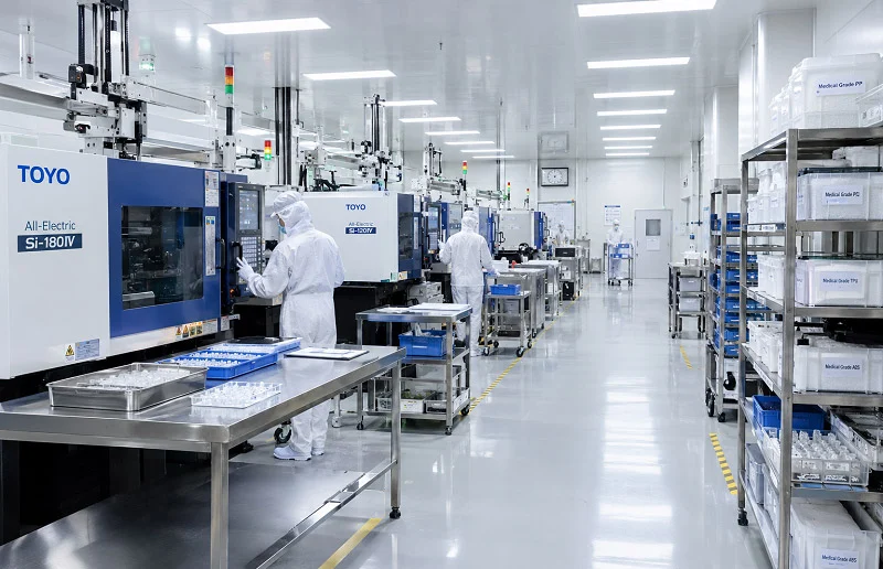
الهندسة هي النقطة التي تتباعد فيها العمليتان بشكل حاد، والنقطة التي تصبح فيها قرارات التصميم التي يتم اتخاذها مبكراً مكلفة للغاية عند التراجع عنها.
Undercuts, Internal Channels And Lattices
Printing builds undercuts, internal channels, lattice structures and enclosed geometries without draft or split lines. Molding handles undercuts through side actions, lifters or sacrificial cores, each of which adds tool cost and maintenance, and some internal geometries are effectively impossible in a rigid mold. Where a part’s function depends on conformal cooling channels or internal lattice, printing is not merely convenient — it is the only route.
Draft, Wall Uniformity And Shrinkage
تفرض عملية التشكيل بالقولبة التزامات تتعلق بمرحلة التصميم. فزوايا السحب - التي تتراوح عادةً بين 1 و3 درجات - ضرورية لتحرير القطعة؛ إذ يؤدي السحب غير الكافي إلى الالتصاق وظهور علامات الاحتكاك وخدوش السطح أثناء الإخراج، بينما قد تؤدي قوة الإخراج المفرطة إلى تشويه الأجزاء أو ترك علامات دبابيس. يجب أن يكون سمك الجدار منتظمًا لتجنب علامات الانكماش والالتواء، كما يجب تعويض سلوك الانكماش في القالب. هذه ليست عيوبًا في عملية التشكيل بالقولبة، بل هي من متطلبات استخدامها، ويجب معالجتها قبل قطع القالب.
Printing removes draft entirely but substitutes its own constraints: properties vary with build orientation, support marks affect surfaces, and thin or unsupported features may not resolve. The constraint moves from the tool to the build setup.
Designing For Additive Versus Designing For Molding
Printing an existing molded-part design is direct part conversion — useful for legacy parts or quick fabrication needs, but it captures little of printing’s benefit. The larger gains come from re-architecting: consolidating assemblies into single parts, replacing solid sections with lattice infill, and routing channels that a mold could never form. That redesign carries its own cost in engineering time, testing and certification, and it should be scoped deliberately rather than assumed.
المواد، والتفاوتات الانتهاء من السطح
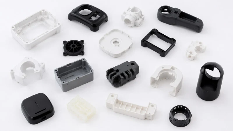
Material and quality requirements frequently override cost. A part that cannot be made in the right polymer, or held to the right tolerance, is not a candidate for the cheaper process.
Material Range And Production-Grade Resins
Molding draws on the full range of production thermoplastics, including filled and engineering grades, with properties established for the application. Material selection directly influences part strength, shrinkage, cosmetic finish, cycle time and long-term dimensional stability, and the right choice begins with functional requirements: mechanical load, temperature exposure, chemical resistance, cosmetic expectations and regulatory considerations.
توفر الطباعة مجموعة أضيق وأكثر تحديدًا لكل عملية. تعتمد عملية البلمرة الضوئية في الأحواض على راتنجات البوليمر الضوئي التي قد تُظهر قوة ميكانيكية محدودة مقارنةً باللدائن الحرارية أو المعادن؛ بينما تعمل أنظمة الطباعة بمسحوق البوليمر مع النايلون والبوليمرات المشابهة؛ أما أنظمة الخيوط فتغطي خيوط الهندسة. عند الحاجة إلى مادة طبية أو إنتاجية، يجب التأكد من ملاءمتها للمادة والعملية المحددة بدلاً من افتراض التكافؤ - فطباعة نموذج أولي باستخدام راتنج بديل لا يضمن أداء بوليمر الإنتاج.
التفاوتات والتشطيب السطحي
Published as-printed tolerances vary by process. FDM is the coarsest at roughly ±0.5% with a floor (tighter on industrial systems), with visible layer stepping. SLA and PolyJet give the finest as-printed surfaces, near injection-molded quality. SLS and MJF sit around ±0.3% with a floor and produce the characteristic grainy matte nylon finish, MJF typically slightly smoother than SLS. These figures assume well-calibrated machines and as-printed parts; warping, support-removal marks, orientation and post-processing all shift the result.
تتميز عملية التشكيل بالقولبة بإمكانية تكرارها: حيث تُؤخذ التشطيبات من سطح القالب وتُعاد إنتاجها في جميع مراحل الإنتاج. وعندما تكون هناك حاجة إلى دقة أعلى من ±0.05 مم تقريبًا، عادةً ما تكون هناك حاجة إلى عمليات تشغيل ثانوية في كلا المسارين، وقد تحتاج الأسطح الحساسة من الناحية الجمالية إلى التلميع أو التخشين بغض النظر عن العملية المستخدمة.
Applications: 3D Printing vs Injection Molding
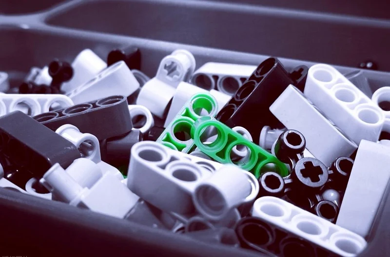
The criteria translate into recognisable application patterns across the industries NOBLE serves — automotive, aerospace, medical devices, robotics, automation, industrial and communication equipment, new energy and consumer products.
أين تتفوق الطباعة ثلاثية الأبعاد
تُتيح الطباعة ثلاثية الأبعاد إمكانية التطوير السريع، وتصميم الأشكال الهندسية المعقدة أو الموحدة، والأجهزة المُخصصة أو المُطابقة للمريض، والإنتاج بكميات صغيرة، وإنتاج الجسور، بالإضافة إلى تركيبات التثبيت. وتصف إدارة الغذاء والدواء الأمريكية الطباعة ثلاثية الأبعاد بأنها تُمكّن من تصنيع أجهزة تتناسب مع تشريح المريض، وأجهزة ذات هياكل داخلية بالغة التعقيد، وتُدرج من بين الأجهزة الطبية المطبوعة غرسات العظام والجمجمة، والأدلة الجراحية، وترميمات الأسنان، والأطراف الاصطناعية الخارجية. وينطبق المنطق نفسه - حرية التصميم الهندسي دون الحاجة إلى أدوات - على الأقواس، والهياكل، والتركيبات في أي مكان قد يُؤدي فيه التعقيد إلى ارتفاع تكلفة القالب.
Where Injection Molding Wins
تُناسب عملية التشكيل بالقولبة التصاميم المستقرة عند الإنتاج بكميات كبيرة، والأجزاء التي تتطلب مواد بلاستيكية حرارية للإنتاج وتشطيبًا تجميليًا متناسقًا، والبرامج التي تُغطي فيها تكلفة الأدوات بشكل مُريح. لكن يكمن التحدي في ترتيب المراحل: يجب تثبيت التصميم قبل قطع القالب. عندما يكون استقرار دورة حياة المنتج والطلب المتوقع قويين، توفر عملية التشكيل بالقولبة اقتصاديات طويلة الأجل يمكن التنبؤ بها؛ أما عندما يكون التصميم عرضة للتغيير، فإنها تُثبّت التكلفة قبل الأوان.
استخدام كليهما في برنامج واحد
التسلسل الشائع هو الطباعة لتحديد الشكل والملاءمة والوظيفة، ثم استخدام القالب للإنتاج. يمكن للنموذج الأولي المطبوع تأكيد الملاءمة، وبيئة العمل، والوظيفة التقريبية، كما يقلل من عدد التعديلات المكلفة على القالب. مع ذلك، لا يؤكد النموذج الأولي المطبوع خصائص المادة المصبوبة، أو سلوك الانكماش، أو قوة خط اللحام، أو جدوى الأدوات، أو اقتصاديات دورة الإنتاج - فهذه تتطلب تجارب أولية واختبارات تأهيل. يُعدّ التصنيع السريع باستخدام حشوات مطبوعة خيارًا مؤقتًا، لكن عمره الافتراضي محدود؛ فهو ليس بديلًا عن الفولاذ المستخدم في الإنتاج.
اختيار نوبل لدعمك مشروع البلاستيك
The decision this article walks through — matching process to part, volume and quality requirement — is the same decision a manufacturing partner has to help you execute. NOBLE is a Sino-British joint venture and an excellent Chinese contract manufacturer, recognised by the government as a National High-tech Enterprise. Our service capability and professional machining expertise help clients complete prototyping and volume production efficiently, carrying a project from design through assembly under one quality system rather than handing it between vendors.
نحن حاصلون على شهادتي ISO 9001:2015 وISO 13485:2016. نقدم باقة متكاملة من الخدمات، بدءًا من التصميم وحتى التجميع، وليس الإنتاج فقط. بالنسبة لمشاريع البلاستيك، يعني هذا إمكانية تطبيق مقارنة العمليات المذكورة أعلاه على التصميم الهندسي والمادة والكمية المطلوبة: الطباعة عندما يكون التصميم لا يزال قيد التطوير أو الكمية قليلة، والقولبة عندما يكون التصميم مستقرًا وتتلاشى تكاليف الأدوات، وتسليم سلس بين المرحلتين عند الحاجة إليهما معًا. تشمل قدراتنا في مجال النماذج الأولية السريعة والتصنيع مجموعة واسعة من المواد المعدنية والبلاستيكية وفقًا للمواصفات المحددة، مدعومة بمعدات فحص داخلية ونظام مراقبة جودة متطور.
إذا كنت تقارن بين الطباعة ثلاثية الأبعاد والقولبة بالحقن لجزء معين، فإن الخطوة التالية المفيدة هي الحصول على عرض أسعار بناءً على ذلك الجزء وحجمه ومتطلبات الجودة الخاصة به.
FAQs about 3D Printing vs Injection Molding
هل يمكن أن تحل الطباعة ثلاثية الأبعاد محل قولبة الحقن؟
For some parts, yes — particularly low volumes, complex geometry and customised devices. For production volumes in engineering thermoplastics with consistent cosmetic finish, molding remains the cost-efficient route once tooling amortises. The two are better treated as complementary stages than as substitutes.
How do I estimate the volume at which molding becomes cheaper?
قارن التكلفة الإجمالية للمشروع - بما في ذلك الأدوات والأجزاء والتشطيب والتغييرات الهندسية المحتملة - عند حجم الإنتاج الواقعي. تتراوح معدلات التحويل المنشورة من حوالي 50 إلى 300 وحدة في إحدى الدراسات القائمة على الطاقة، إلى 500 إلى 2,000 وحدة في التوجيهات العامة، وأكثر من 13,000 وحدة في حالة مكون محدد، وذلك لأن حجم الجزء والمادة والتجويف وتكلفة الأدوات كلها عوامل تؤثر على هذه المعدلات.
Can a printed prototype be used to approve a mold?
It can confirm fit, ergonomics and rough function, and it reduces costly mold revisions. It does not confirm molded material properties, shrinkage, weld-line strength, tool feasibility or cycle economics. Trial shots and qualification remain necessary before production approval.
Can the same design be used for both processes?
Often only with modification. A molded design carries draft, uniform walls and shrinkage compensation that printing does not need; a printed design may include lattices or internal channels a rigid mold cannot form. Printing an existing molded design is possible, but it captures little of printing’s design freedom.
كيف يختلف اختيار المواد بين الاثنين؟
Molding covers the full range of production thermoplastics, including filled and engineering grades. Printing offers a narrower set of process-specific materials — photopolymers, nylon powders, engineering filaments. Start from functional requirements and confirm medical-grade or production-grade suitability for the specific material and process.
What tolerance and finish should I expect from each?
تختلف دقة الطباعة النهائية باختلاف العملية: تُعدّ تقنية FDM الأكثر خشونة بدقة ±0.5% تقريبًا، بينما تُعدّ تقنيتا SLA وPolyJet الأكثر دقة، أما تقنيتا SLS وMJF فتُعدّان الأكثر دقة بدقة ±0.3% تقريبًا، مع سطح نهائي غير لامع وخشن. ويمكن تكرار عملية التشكيل من سطح القالب. وتتطلب الدقة الأقل من ±0.05 مم عادةً عمليات تشغيل ثانوية في أي من الطريقتين.
Verdict: matching the process to the part
طبّق القاعدة مباشرةً. اختر الطباعة ثلاثية الأبعاد عندما يكون التصميم لا يزال قيد التطوير، أو عندما يكون الشكل الهندسي معقدًا أو ثابتًا، أو عندما يكون حجم الإنتاج منخفضًا لدرجة لا تسمح باسترداد تكلفة الأدوات. اختر قولبة الحقن عندما يكون التصميم مستقرًا، وتكون جودة المواد المستخدمة في الإنتاج والتشطيبات المتكررة مهمة، ويكون حجم الإنتاج مبررًا لاستخدام الأدوات. عندما يتطلب البرنامج كلا الخيارين، اطبع للتحقق من صحة التصميم واصنع القوالب للإنتاج، واعتبر الأدوات السريعة مرحلة انتقالية وليست غاية نهائية.
The crossover is part-specific. The practical next step is a quote based on your actual part, volume and quality requirement — which is exactly what NOBLE can provide, from prototype through production.