Why CNC Machining Matters for Embodied Robots
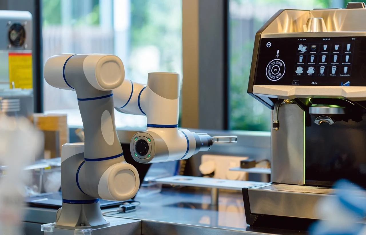
When you see those embodied robots doing backflips right in front of you, do you ever worry that they might fall apart or malfunction? Joints flex. Arms extend. The whole structure experiences real forces—gravity, inertia, and impact.
So the hardware has to be stiff, lightweight, and precise.
Two processes dominate this space for prototyping and low-to-medium volume runs. CNC machining and sheet metal fabrication. Both are accessible. Both produce real parts quickly. But they serve different purposes.
These two processes are also really important for making embodied robots. Then I’ll show you how CNC machining and sheet metal fabrication work together to build an embodied robot, step by step.

CNC-Machined Components (The Precision Core)
Some parts define the robot’s performance. They take the loads. They set the accuracy. Without them, the whole machine drifts and fails.
Joint Housings
You’ll find these at the shoulders, hips, knees, and ankles. Each one can handle the full force of a limb swinging or a body shifting position. The housing needs precise bores. The bearings press in snugly. The seals sit concentric to the rotating shaft.
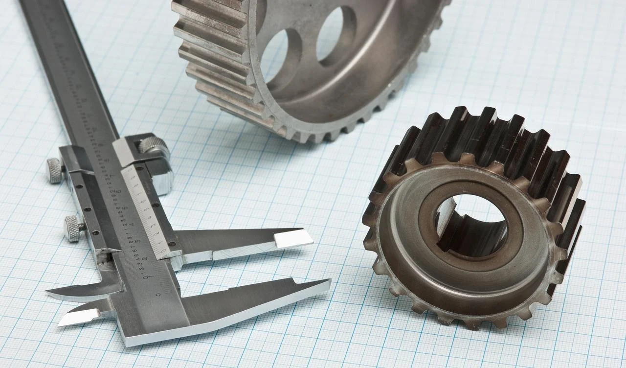
Unless the customer has specific requirements, we tend to use 6061 or 7075 aluminium to manufacture these parts. 5-axis CNC machining is the best way to go. The tool can reach undercuts and angled faces in one setup. But a skilled machinist can also make the same part on a three-axis mill. It just takes multiple setups, more fixturing, and careful requalification of datums. The five-axis path is faster and more accurate. The three-axis path is cheaper for small runs.
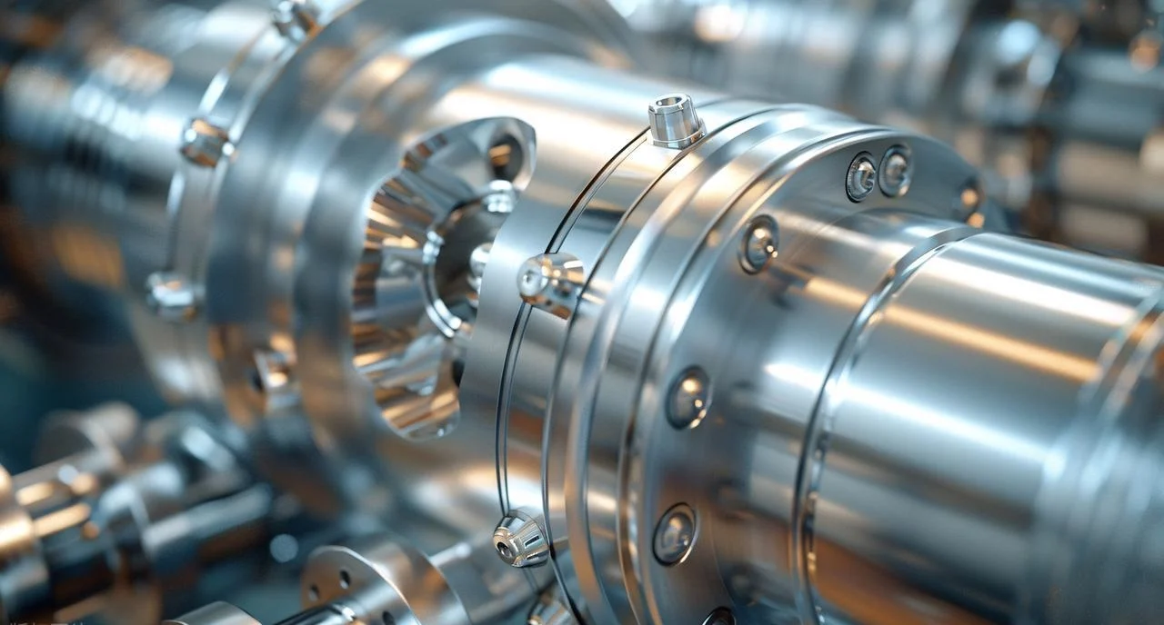
Rotary Transmission Shafts
These parts spin. They transfer torque from a motor to a joint. The geometry is a bit tricky. Bearing journals need tight diameter control. Splines or keyways transfer rotation without slipping. The threaded bits hold the retaining nuts or pulleys. A lot of shafts have got internal through-holes as well. Wires for sensors or power pass right through the middle of the rotating assembly.
We use CNC lathes with live tooling to make these shafts. The lathe does the hard work of turning the outer diameters. Live tooling mills the flats, drills the cross-holes, and cuts the keyways without having to remove the part from the spindle. When it comes to complex shafts, it’s usually best to go for a five-axis turn-mill centre. They handle off-axis features and angular ports in one clamping.
The material path is important here. First things first, get the shaft roughed in. Just make sure you keep stock of critical diameters. Then send it off to heat treatment. The target hardness ranges from HRC 45 to 60, depending on the alloy and how much wear it can take. Once the heat treatment’s done, it’s time to finish-grind the bearing journals and seal surfaces. Grinding gets really precise with hardened steel, which turning just can’t match. The result is a shaft that spins true, wears slowly, and will last as long as the embodied robots are supposed to.
Torso Chassis (Main Mounting Plate)
This is the robot’s backbone. Everything connects to it. Computers, batteries, actuators, cable management systems. The plate gives you flat, parallel reference surfaces. If the plate gets bent or twisted, nothing else will line up right. Your robots will end up standing crookedly.
We make this from an aluminium plate. The thickness varies between 12 and 25 millimetres, depending on the robot’s size and how it’s built. The machining job is straightforward but a bit of a slog. There are hundreds of threaded holes, all drilled and tapped to within an inch of their life. If you get a hole in the wrong place on a plate, it can cost you a lot of money. Shops use CNC machining centres with probing cycles to check hole positions before tapping.
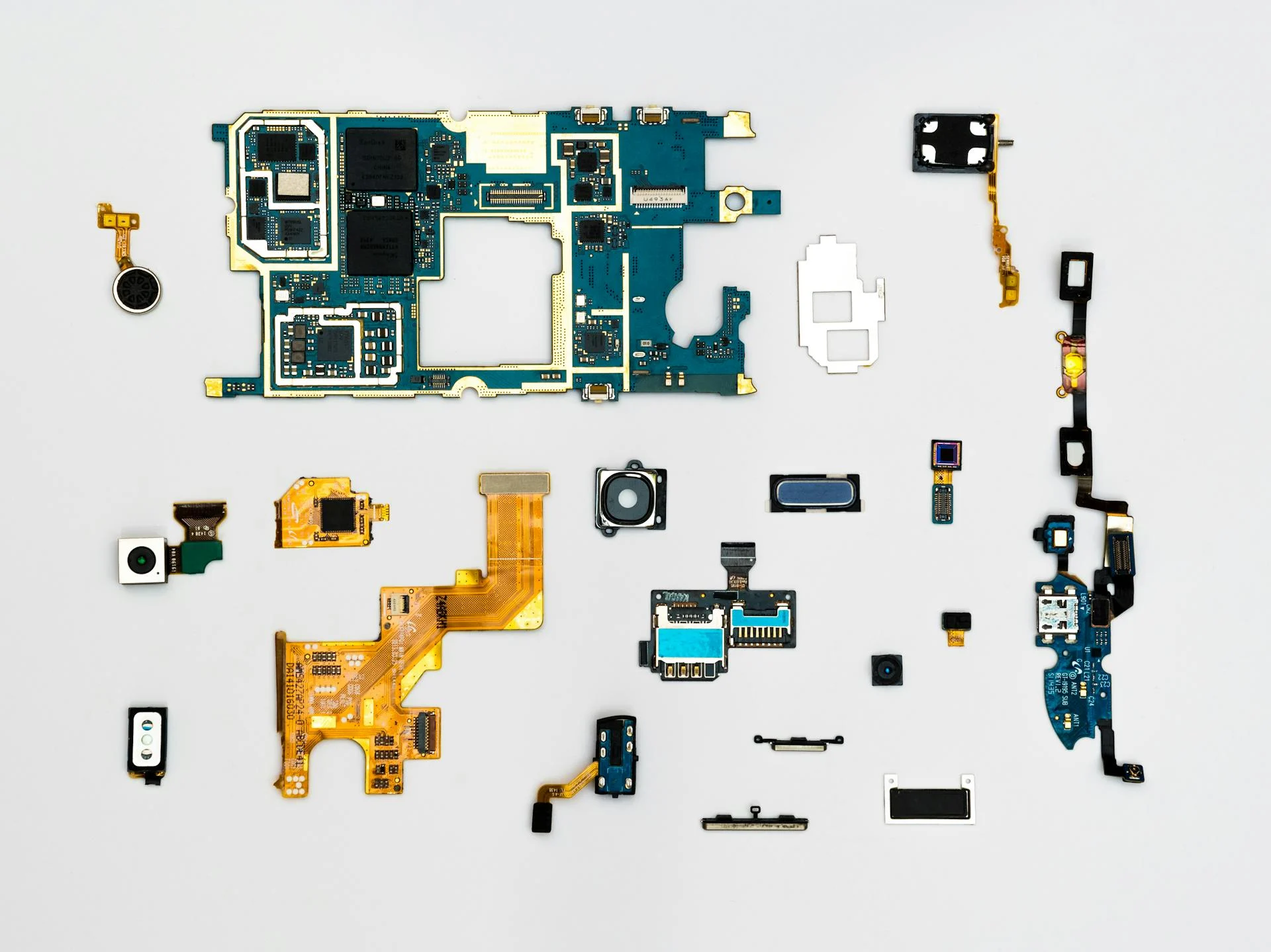
Small Precision Parts
Not every component is a structural bulkhead. Some parts are tiny. They demand different machines and different thinking.
Finger bones and hand links are small, complex, and numerous. A humanoid hand might have about fifteen or twenty articulated links. Each one has bearing surfaces, pivot holes, and cable guides. Swiss-type lathes are the perfect choice in this case. They use machines to cut long, thin parts from bar stock with exceptional concentricity. For even smaller features, micromills are the way to go. The tools we use have a diameter of less than one millimetre. The feed rates are measured in microns per tooth.
Force/torque sensor flexures are a whole other challenge. These are thin-walled elastic structures. They’re a bit squishy when you put them under pressure. Strain gauges measure that deformation. The part has to spring back perfectly every time. If there’s too much material, the sensor can become insensitive. It just doesn’t make enough to change things permanently. If you’re machining these from aluminium or 17-4PH stainless steel, you’ll need to be careful with your toolpath control. Any cutter mark becomes a stress concentration. Lots of shops end up throwing away half their first batch when they find this out.
Bearing retainer plates and encoder mounts are simpler but still precise. They find bearings axially. They hold encoder readheads at exact air gaps. Tolerances matter, but the geometry is usually pretty straightforward.
Design Rules for CNC Machining (Bulleted list)
You want to know what I think? What should you pay special attention to? I’ve put together a few points that I hope will be helpful.
- Try to avoid tight, narrow pockets where possible. Any pocket that’s more than four times as deep as it is wide is a problem. Chips don’t clear easily. The coolant can’t get to the cutting zone. Long, skinny end mills can chatter or break. Redesign the part or add a through-hole to make it easier to get the chips out.
- Just use standard end mill radii for internal corners, okay? The most common radii are 1.5 mm, 3 mm, and 6 mm. These match off-the-shelf tools. If you’ve got a non-standard radius, say 4.2 mm, then the shop’s going to have to custom-grind a tool or use multiple passes to clear the corner. Both options add cost and lead time.
- Just specify tight tolerances when you really need to. A bearing journal or a gear mounting surface really needs ±0.005 mm. A cosmetic outer profile doesn’t. A lot of designers set tight tolerances on every dimension. That just ends up costing more without improving how well it works. Just be careful about who you choose.
- The idea is to design for minimal setups. Whenever we take a part off the machine and refit it, the accuracy goes down and the cycle time goes up. If a part is machined in one or two setups, it’ll cost half as much as a part that needs five setups. Orient features are only accessible from one direction. Try to avoid undercuts unless you really have to. Design for the machine, not just for the function.
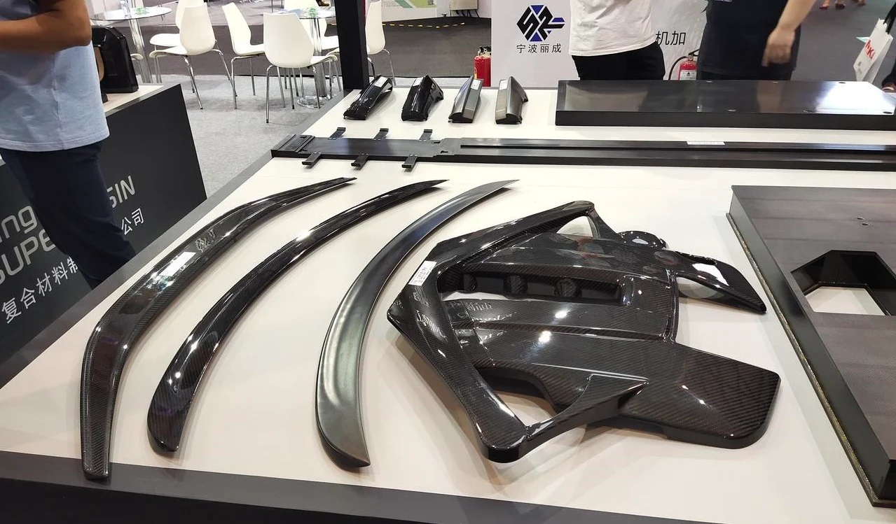
Sheet Metal Fabricated Components (The Lightweight Frame)
Embodied robots are highly complex, but there are still some components that need to be rigid, lightweight, and inexpensive. This is where sheet metal really comes into its own. It’s used to create the robot’s skin and secondary structures.
Torso Enclosures and Panels
Think about side panels, back covers, and top decks. These keep dust out and cables in. They also make the robot look finished. We all know that a tangle of wires hanging off a prototype is an eyesore.
We use a laser cutter to make our products. The machine cuts flat blanks from 1.5 to 2 millimetre aluminium sheets. There are holes to allow air to circulate. There are cut-outs for cable pass-throughs. Then the part moves to a press brake. The brake bends, flanges, and shapes the 3D design.
PEM nuts are a standard detail here. These are press-in threaded inserts. A shop will install them after bending them. The insert sits flush with the sheet surface. Now, you can use a thin aluminium panel with a steel bolt without stripping the threads. Easy peasy. It works a treat.
Leg and Arm Links
An embodied robot’s limbs do not have to be solid metal. C-channels and closed boxes work well. Both come from bent sheet metal.
One common approach uses two U-channels. Each channel is a simple bent shape. An assembler places them back-to-back and rivets the flanges together. The result is a closed box section. Stiff in bending. Stiff in torsion. Light because most of the material is at the outer surfaces. This is the same principle as an I-beam or a bicycle frame tube.
These sheet metal links bolt or rivet directly to the machined joint housings. The housing provides the precision bearing surfaces. The sheet metal link provides the structural reach. Each material does what it does best.
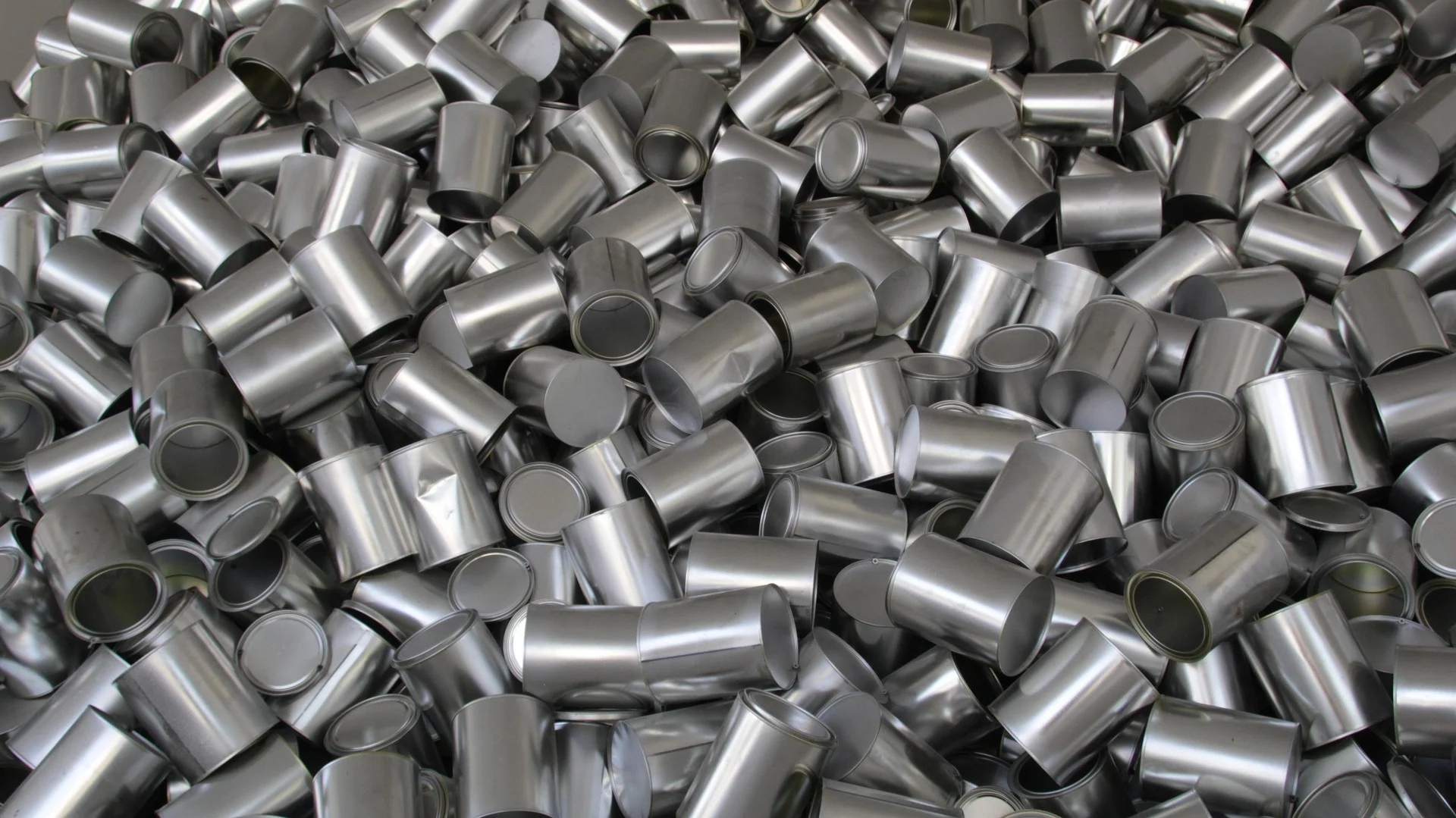
Battery Enclosures
Lithium-ion cells need protection. A puncture can start a fire. A dent can cause an internal short. Battery enclosures are just bent boxes with lids you can take off. The sheet metal provides impact resistance. It also stops the cells from accidentally coming into contact with tools or debris during maintenance.
Designers have added bent tabs to these enclosures. The tabs have holes in them. The holes line up with the threaded inserts on the torso chassis. A few screws hold the whole battery pack in place. It only takes seconds to remove. Replacing it is a piece of cake. The sheet metal enclosure is a bit plain. It just works, and it works reliably.
Electronics Mounting Brackets
Sensors and circuit boards need homes. Mounts don’t have to be complicated. Simple L-brackets and Z-brackets work well. People use them for cameras, LiDAR units, and microcontrollers.
The process is pretty quick. Get a flat pattern from an aluminium sheet that’s between 1 and 1.5 mm thick. Just bend it on a press brake. Job done. Turnaround is measured in days, not weeks. This speed is really important when you’re doing the first version of a product. Do you need to reposition a sensor? Design a new bracket. Just cut it. Bend it. Give it a go. The whole cycle takes an afternoon.
Foot Plates (Simple Version)
The foot plate is what transfers ground reaction forces into the leg structure. The basic version is just a flat plate.
Waterjet cutting is the best option here. There’s no heat-affected zone. No rough bits that need extra tidying up. The plate stays flat and stress-free. Then, after cutting, a shop drills and taps mounting holes for the force/torque sensor.
Our engineers tend to use spring steel instead of aluminium for higher durability. The plate bends a bit when there’s pressure on it, but then goes back to flat. It’ll last longer before cracking. The trade-off is weight and corrosion resistance. Spring steel is heavier and will rust if it’s not coated.
Design Rules for Sheet Metal Fabrication
These rules help to keep parts manufacturable. If you don’t, a shop might call back and ask for changes or charge more.
- Make sure the hole’s diameter is at least as big as the material thickness. You’ll need to make sure there’s at least a 1 mm hole in each 1 mm sheet. Smaller holes need special tools or extra drilling. They both add cost.
- Make sure you keep the hole-to-bend distance. The rule of thumb is 2.5 times the material thickness plus the bend radius. If you put a hole too close to a bend, it’ll distort. The material stretches outwards at the bend. The hole ends up being more oval-shaped. The fasteners don’t fit anymore.
- The design should have a flange height that’s at least four times the thickness of the material. If the flange is too short, it won’t be possible to form it accurately. The press brake die needs enough material to grip. Short flanges also lack stiffness. They wobble under load.
- Add radiused fillets to the internal corners. Sharp corners can put a lot of pressure on a surface. If you’ve got a bent part, a sharp internal corner is a crack waiting to happen. A radius distributes the load. The part lasts longer. The rule applies to both the flat pattern and the final formed shape.
- Just so you know, it’s important to specify the bend direction relative to the material grain, especially when it comes to aluminium. Sheet metal has a grain direction from the rolling mill. Bending across the grain makes it stronger. Bending with the grain can lead to cracking on the outside of the bend. Experienced designers will flag this up on the drawing. If you’re inexperienced, you’ll probably learn about it after your first batch of parts fails.

Hybrid Assemblies (Machined + Formed)
It is impossible to build an entire embodied robot using just one manufacturing process. The process is extremely complex, but our general approach is to use CNC machining for parts where precision and strength are critical and sheet metal fabrication for parts where weight and cost are more important. We then assemble these parts.
Leg Construction Pattern
Take a look at an embodied robot leg, from the hip to the foot. It has three joints: the hip, knee, and ankle. Each joint requires a machined housing. The bearing bores must be concentric. The mounting faces must be parallel. The seal grooves must be clean. This is the realm of CNC machining.
Now, consider the links between those joints. Thigh. Calf. These are long, structural bodies. They need to be stiff along their entire length. However, they do not need the density of a solid aluminium block. Sheet metal channels are ideal for this purpose. A U-channel or closed box section provides bending stiffness at a fraction of the weight.
The assembler bolts or rivets the machined housing to the sheet metal channel. The housing then holds the precision joint. The channel holds the two housings apart at a fixed distance. Each part does its job. Together, they work as a unit.
Torso Construction Pattern
The torso is designed using a similar logic, but with different proportions.
A central spine plate, machined from a single piece of metal, runs down the middle. This forms the rigid backbone. Actuators are mounted directly onto it. Computers and batteries are bolted to its surfaces. The spine plate must be flat, strong, and precisely drilled. CNC machining from a thick aluminium plate is the right method.
Around this dense core, sheet metal side, front, and rear panels are added. These serve two purposes. Firstly, they enclose the internal components. There are no exposed wires. Second, they prevent fingers from poking into moving parts. Secondly, they increase torsional stiffness. A closed sheet metal box resists twisting far more effectively than a single flat plate.
This combination is efficient. A machined core can handle concentrated loads and precision interfaces. A sheet metal shell can handle broad surfaces and enclosure requirements. Together, they weigh and cost less than a fully machined torso.
Hand Construction Pattern
Although the hands are small, the pattern remains consistent.
Precision features are provided by CNC-machined, embodied robot metal finger bones. There are pin holes for the joints. There are also cable guides for the tendons. There are also flat surfaces for linkage attachments. Although each bone is small, the tolerances are tight. These can be produced in quantity using a Swiss-type lathe or a micromill.
The palm can use sheet metal plates. Thin material. Bent flanges. These form the curved shape of the palm. They also provide mounting points for the finger bones.
Small rivets or screws hold the assembly together. The machined finger bones pivot on precision pins. The sheet metal palm provides support. The result is a hand that moves smoothly, weighs little, and is much cheaper than a fully machined alternative.
CNC Machining vs. Sheet Metal Fabrication
People ask which method is better. That is the wrong question. Each process solves a different problem. The table below shows how they differ.
| Aspect | CNC Machining | Sheet Metal Fabrication |
| Best for | Bearing bores, threaded precision holes, complex 3D geometry. | Flat or bent plates, simple brackets, enclosures, and structural skins. |
| Typical volume | Low volume. 1 to 100 units. | Low to medium volume. 10 to 500 units. |
| Tooling cost | None. No molds or dies. | Low. Simple press brake tooling. Laser cutting needs no hard tooling. |
| Per-part cost | High. Material waste is significant. | Low for runs of 10 or more units. |
| Lead time (prototypes) | 1 to 2 weeks. | 3 to 7 days. |
| Strength-to-weight | Good, but dense. | Excellent. Thin material carries load efficiently. |
| Geometric complexity | Very high. Undercuts, deep pockets, compound angles. | Low. Limited to bendable shapes. |
When to Choose CNC Machining
Choose CNC machining for parts that require bearing bores. These bores must be perfectly round and within a few microns of the required size. Choose it for threaded precision holes that align exactly with mating components. Choose it for complex three-dimensional geometries that cannot be approximated by a flat sheet. Joint housing. A sensor bracket with compound angles. A custom gear blank.
The upfront cost is low. There is no tooling to buy. However, the per-part cost is high. A machined part starts life as a solid block. Most of that block becomes chips on the factory floor. For production runs of between one and one hundred parts, this trade-off makes sense. For larger volumes, however, we start looking at other methods.
When to Choose Sheet Metal Fabrication
Choose CNC machining for embodied robot parts that require bearing bores. These bores must be perfectly round and within a few microns of the required size. Choose it for threaded precision holes that align exactly with mating components. Choose it for complex three-dimensional geometries that cannot be approximated by a flat sheet. Joint housing. A sensor bracket with compound angles. A custom gear blank.
The upfront cost is low. There is no tooling to buy. However, the per-part cost is high. A machined part starts life as a solid block. Most of that block becomes chips on the factory floor. For production runs of between one and one hundred parts, this trade-off makes sense. For larger volumes, however, people start looking at other methods.
Cost and Lead Time Considerations
The lead time for CNC machining prototypes is 1–2 weeks. The bottleneck lies in programming and setup. Once the machine is running, it produces parts quickly. However, each part requires a significant amount of machine time. The high per-part cost reflects this.
Sheet metal fabrication is faster. The process takes three to seven days from drawing to finished part. Laser cutting is rapid. Bending is also rapid. For orders of ten or more units, the per-unit cost drops significantly. The first part takes the same time as the tenth.
The hybrid approach is the most cost-effective solution for complete robots. Machine the precision joints. Form the structural links. Bolt them together. The total cost is lower than that of an all-machined robot. The total weight is also lower than that of an all-sheet-metal robot. Those who understand both processes can build better machines faster.

Choose NOBLE for embodied robot manufacturing
Who We Are
NOBLE is a precision CNC machining company. We have extensive experience in producing robotics, automation, and medical devices.
We bridge the gap between prototyping and production. Many companies either specialise in one-off projects or high-volume production. We handle both. We produce single-unit runs for testing. We also handle mid-volume production ranging from 1 to over 1,000 units. We use the same machines for both. Same quality standards. We pay the same attention to detail.
Core Machining Capabilities
CNC Milling
We offer three-, four-, and 5-axis CNC milling. We maintain tolerances of ±0.005 mm (±0.0002 inches) for critical features. Our high-speed machining capabilities handle aluminium and thin-wall components without chatter or distortion.
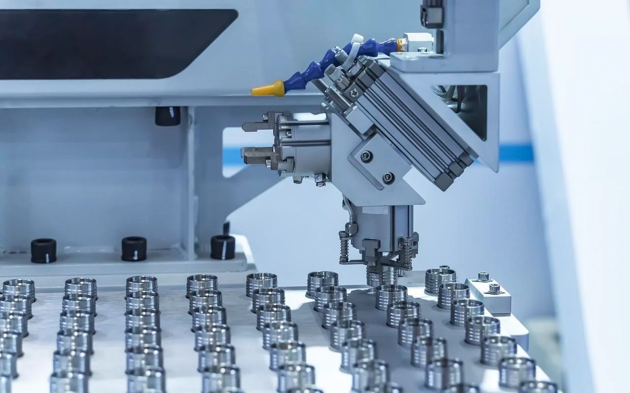
CNC Turning
We have live tooling lathes with Y-axis capability. Swiss-type automatic lathes are used for small, complex parts. These are used for finger bones, micro-shafts, and sensor components. The Swiss lathe runs bar stock and produces finished parts in one cycle.
Supporting Processes
Both surface grinding and cylindrical grinding produce bearing-quality finishes. We achieve a Ra value of 0.4 micrometres or better on ground surfaces.
Heat treatment is carried out either in-house or through qualified partners. We offer annealing, hardening, and stress relieving. NOBLE manages both the process and the documentation.
Post-machining finishing includes deburring, anodising (clear and Type III hard coat), passivating stainless steel, and media tumbling to create a uniform surface texture.
Certifications
ISO 9001:2015
NOBLE has obtained quality management system certification, which ensures that all processes, from manufacturing and inspection to shipping, are managed in accordance with established standards. ISO 9001:2015 certification guarantees the consistent quality, traceability, and continuous improvement of our parts. This means that our customers can be sure of receiving parts that meet specifications every time.
ISO 13485:2016
In addition to ISO 9001 certification, we have obtained certification for the management of medical device manufacturing. This is particularly relevant in the context of robotic surgical instruments, medical exoskeletons, and rehabilitation robots. The standard requires stricter documentation, more formal risk management, and more thorough process validation than ISO 9001 alone demands. We maintain all of it.
FAQ
What types of robot components are best suited for CNC machining rather than 3D printing or sheet metal?
Joint housings. Rotary shafts. Any part that needs bearing bores or tight tolerances in the range of ±0.005 mm. These parts carry loads and locate moving components. 3D printing suits complex, low-load brackets where strength is secondary. Sheet metal suits enclosures and structural links where geometry is simple.
What materials do people recommend for robot structural components?
Aluminum 6061-T6 is the workhorse. Good strength. Easy to machine. Reasonable cost. For higher strength, 7075-T6 is the choice. It machines well but costs more. For joint housings that need surface hardness and wear resistance, 17-4PH stainless steel is common. It heat-treats to high strength and resists galling. For lightweight, non-metallic components, PEEK and Delrin (acetal) work well. They are stiff, stable, and machinable. No corrosion concerns.
How do people choose between CNC machining and sheet metal for a given part?
A simple rule covers most cases. If the part has bearing bores, complex three-dimensional geometry, or requires tight tolerances, choose machining. If the part is a flat or bent plate with fastener holes and no precision interfaces, choose sheet metal. When a part has both types of features, people often design it as an assembly. Machine the precision core. Form the sheet metal shell. Bolt them together.
What design features increase the cost of a machined part?
Deep, narrow pockets are problematic. When pocket depth exceeds four times the tool diameter, chip evacuation becomes difficult. Tool breakage becomes likely. Cycle time increases dramatically.
Sharp internal corners are another issue. A square internal corner requires a special tool or a secondary operation. A radiused corner allows a standard end mill. People should add fillets wherever possible.
Unnecessarily tight tolerances on every feature drive cost without adding value. A bearing bore legitimately needs ±0.005 mm. An outer profile does not. Specify tight tolerances only where function demands them.
Can people manufacture parts for medical robots or surgical devices from NOBLE?
Yes. NOBLE holds ISO 13485:2016 certification. This is the quality management standard for medical devices. It demonstrates our capability to machine components for healthcare applications. For these jobs, we maintain full traceability. Material certifications. Inspection records. Process documentation. Clients receive a complete package suitable for regulatory submissions.
What is the quality inspection process?
In-process inspections happen during machining. Operators check critical features at defined intervals. They record results on the shop floor documentation.
Final inspection uses calibrated equipment. CMM for dimensional accuracy. Bore gauges for internal diameters. Thread gauges for threaded features. Optical comparators for complex profiles and small features.