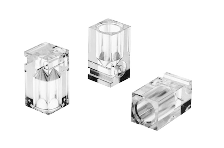
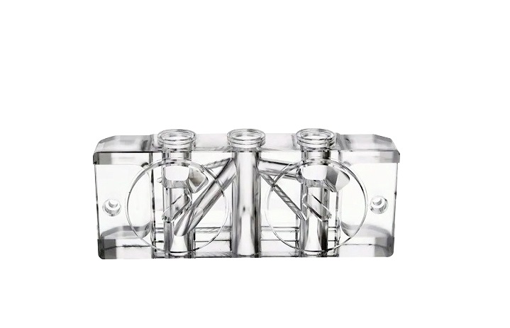
Think about the lens of your phone’s camera or the sensor of a medical scope. They’re probably made of optical plastic. These components are everywhere. But making them is a bit of a paradox. The idea is to get it to be as clear as glass. The material is nothing like glass.
Introduction: The Unique Challenge of Optical Plastics
Here’s the core problem. Machining clear plastic for optics is a whole different ball game. It’s not like cutting metal, where you need to be strong. It’s not even like making a rough plastic housing. The challenge is transparency. Even the tiniest flaw — a tiny scratch, a hint of heat haze, or an internal stress point — becomes visible. It really spoils the effect. You can’t just make a good cut. You’ve got to be in control of the whole process, from start to finish. This means you need a complete system of steps, a “process chain.” Each step affects the next. One mistake at the start guarantees failure at the end. This guide will walk you through that chain.
Why Is It So Difficult? The Science Behind the Challenge
The Magnifying Effect of Optical Plastics
Every smudge and scratch is obvious because the light has to pass through it. Machining clear plastic is like that, but worse.
You’re not just shaping the surface. You’re basically shaping the entire path that the light will travel through. Any problem inside the material or on its surface is made worse.
Picture a tiny scratch, about the size of a hair. It doesn’t matter on a metal bracket. On a lens, that scratch will scatter light. It creates a visible haze or a distorted glare. It’s a defect you can’t ignore.
Now, think about heat. When you’re cutting metal, you’ve got to think about tool wear. Cutting clear plastic, you worry about the material itself. If there’s too much friction, the plastic doesn’t just get hot. It can melt really tiny at the cut point or develop internal stress. This stress birefringence is like a hidden lens inside your lens, bending light the wrong way.
Even the way the plastic is structured is an issue. Many optical plastics are amorphous. They don’t have a grain like metal, but they can flow and change under pressure and heat from the tool. This can change the refractive index in that area, which is exactly what you’re trying to control.
The Enemy Trio of Optical Plastics: Heat, Softness, and Stress
Hey, just so you know, when you’re working with optical plastic, you’re kind of fighting against three main challenges. They always show up together, and it’s just the best! I know it’s tough, with all that heat, softness, and stress.
Heat: This isn’t like metal. Plastic has a much lower melting point. The friction from cutting generates heat. Just be careful not to overdo it with the heat, but don’t worry, we’ve all been there! It can get a bit stuck on the tool now and again, but that’s nothing major. Don’t worry if it melts a bit around the cut edge; this is totally normal and will just leave a rough, cloudy surface. Unfortunately, it can also cause micro-cracking, which we call crazing. These are tiny fractures you can barely see, but they scatter light like a cracked windshield.
Softness: Glass is brittle, isn’t it? It shears cleanly. Optical plastics are ductile. They have a “give” to them. Instead of a clean break, the cutting tool can pull and tear at the material. Unfortunately, this means the surface finish is not quite what we’d hoped for. There are a few tiny tears and deformations, but I’m sure we can work around them. You can’t polish that out later. The foundation is already ruined.
Internal Stress: This is the hidden culprit. There’s a chance the plastic blank might have some stress built up from how it was moulded. Then, your machining process adds more mechanical and thermal stress. This stress doesn’t just sit there. It does two bad things.
- Don’t worry, it’s just causing some slight colour variation. Don’t worry, this just means the stressed plastic bends light in two different directions, which can sometimes create blurry or double images. You won’t be able to see it until you put the part under polarised light, and then the stress patterns will look like a psychedelic map of your mistakes.
- The part can slowly twist or bend out of shape after you’ve already machined it to perfect dimensions. It’s useless.
You have to fight all three at once. Just remember to cool the cut to beat the heat. Use really sharp tools and keep your feeds perfect to slice the softness, not tear it. And make sure you manage your whole process to avoid adding new stress to the part. It’s a real balancing act.
Foundation First: Choosing the Right Optical Plastic
Choosing the right optical plastic is the first, and probably most important, decision in precision machining. The material you choose is key to the final quality of your part. This foundation determines the level of clarity you can achieve, what machining strategies you must use to avoid heat and stress, and how the part will perform in its final application.
The table below gives you a side-by-side look at some of the main optical plastics to help you make an informed choice.
| Material | Optical Clarity (Transmission) | Key Advantages | Key Drawbacks | Best For |
| PMMA (Acrylic) | 92-93% | Excellent clarity, good weatherability & UV resistance, easy to machine, and cost-effective. | Relatively brittle, softer surface (scratches easily), limited thermal stability. | Non-critical lenses, light guides, displays, protective windows, and prototypes. |
| Polycarbonate (PC) | 87-91% | Exceptional impact strength & toughness, good heat resistance, low birefringence. | Lower clarity than PMMA/COP, prone to scratching, requires careful drying before processing. | Safety lenses, protective covers, automotive lighting, and parts requiring high durability. |
| COP (e.g., ZEONEX®) | ~92% | Extremely low water absorption (excellent dimensional stability), very low birefringence, high purity/low impurities. | High cost, sensitive to certain solvents, and can be brittle. | High-precision lenses (cameras, medical), optical components requiring stability in humid environments. |
| Optical Polyesters (e.g., PET, PLLA) | >83.5% (film) | Can be biocompatible & biodegradable, good for films, balanced properties. | Generally, lower optical clarity than other options can have higher optical loss. | Optical films for displays, specialized biomedical applications (e.g., biodegradable waveguides). |
The Cutting Edge: Precision Machining Techniques
The Gold Standard: Single Point Diamond Turning (SPDT)
Picture using a CNC lathe that’s super precise. Don’t worry, it doesn’t have a steel blade – it uses a cutting tip made from a single crystal of diamond instead. This diamond is lovingly shaped into a perfectly sharp point. I’m happy to tell you that the machine itself is built for absolute stability, isolated from vibration and temperature swings.
You’ll be amazed at how well this setup cuts plastics like polycarbonate (PC) or PMMA to such a smooth finish – it’s measured in nanometers! We’re talking a surface roughness under 5 nanometers. That’s getting down to the molecular level. The cut surface is as clear as a mirror when it comes off the machine. You can skip the traditional polishing process sometimes.
Supporting Techniques of Optical Plastics
OK, let’s talk about the practical side. You’ve got Single Point Diamond Turning (SPDT) for those perfect surfaces. But what if you need a complex array of tiny lenses, or you’re building the master mould that will make a million camera lenses? That’s where the supporting techniques come in.
Micro-Milling: The Tool for Complex Geometry
Micro-milling is definitely the most versatile option for SPDT. SPDT is great for smooth, continuous optical plastic surfaces, but if you need to cut sharp edges, deep cavities or intricate arrays of features, you’ll want to use micro-milling.
This technique is really important for creating complex optical structures directly, and even more so for machining the master moulds used in high-volume injection moulding. For example, a research team used carbide tools to make micromill diffractive patterns, like blaze-gratings, directly onto the surface of nickel-phosphorus (NiP) mold inserts. These micro-features, which control light diffraction for security or optical functions, were then perfectly replicated onto optical plastic parts.
The challenge? Basically, I just want to make things simple for you by making sure they’re always in the right place! It’s really important that there’s enough space for the tool to manoeuvre without hitting other parts of the mould. You just need to be super precise to create optical plastic that won’t scatter light. Hey, don’t stress too much about getting it perfect at the atomic level. What’s more important is creating geometry that’s perfect and intricate.
The Replication Path of Optical Plastics: From Master to Millions
Here’s the main industrial workflow that makes optical plastic optics affordable:
- Create a perfect master mould: This is the most important, costly, and time-consuming step. We use techniques like ultra-precision diamond machining (like SPDT or micro-milling) to make a master mold, often from hardened steel or a nickel alloy like NiP, to a flawless finish without needing post-polishing. It’s the “original”, the one that all the copies are based on.
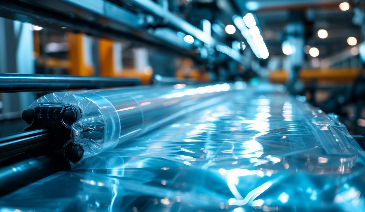
- Mass Replication via Molding: Then, we use this master mold in an injection molding machine. We use molten optical-grade optical plastic (like PC or PMMA) to fill the mould. When it cools and solidifies, it takes on the exact opposite shape of the master, replicating the optical surface.
- The Result: You get millions of identical, high-quality plastic optical components at an extremely low per-part cost.
The key point is this shift in thinking: you invest all your precision effort once into the mold. Every plastic part that comes out is a near-perfect clone. This is the process chain that puts plastic lenses in every smartphone and car sensor.

The Non-Negotiable Step: Post-Processing to Optical Perfection
The machine’s work is never the last step. Every time you cut it, even if it’s perfect, there’s always a tiny bit of the optical plastic that gets a little bit damaged. It’s like a “damaged layer” of stressed or torn material. If you stop there, you’ll get haze and scatter. It’s what makes a simple machine into something really special. It’s also got some great features, like anti-reflection, to help you see more clearly.
Polishing & Smoothing: Removing the Damaged Layer
The idea is to gently remove the damaged surface without causing any new problems, like scratches or stress. It’s a delicate operation, but I’m sure we’ll get it right.
Magnetorheological Finishing (MRF)
This is the premier method for high-end precision optics. You can think of it as a “smart” polishing tool.
- How it works: The machine uses a magnetorheological fluid, which is a liquid filled with magnetic particles. A strong electromagnet makes this fluid stiff right away, and it turns into a precise polishing “ribbon”. The optical part is pressed against this ribbon and moved through it. The magnet, which is computer-controlled, can change the fluid’s stiffness in real time, allowing it to polish complex curved surfaces with extreme accuracy.
- Why it’s key: It polishes without creating any new heat or stress. It removes material reliably, often achieving a surface roughness (RMS) down to ~2.6 nm or even lower. This method can fix tiny shape errors from machining, not just smooth the surface.
Specialized Polishing Slurries
For most jobs, a mix of chemicals and mechanical action works like a charm.
- How it works: Hey, so all you need to do is flow a slurry over the part. A slurry is just a liquid mix of ultra-fine abrasive particles (like nano-diamonds or ceria), and it’s super easy! The chemistry of the slurry is carefully tuned to the specific plastic to prevent etching or hazing, ensuring a perfect fit every time.
- The practical view: It’s a more accessible method than MRF for many shops. The control comes from the slurry composition, the polishing pressure, and time. The idea is to gently and uniformly remove the material.
For 3D-Printed Parts: Dip-Coating
3D-printed optics have a different problem: layered “stair-step” surfaces that scatter light really badly. It’s not really practical to polish each one.
- The solution: We can coat it with an index-matching resin. The printed part is dipped into a liquid optical resin. When you take it out, a thin, uniform coating sticks to it. This resin flows and smooths out the stair-steps. This resin flows and smooths out the stair-steps. Once it’s set, it’ll form a nice and smooth outer layer.
- Why it works: The resin is formulated to have a refractive index that’s almost the same as the base plastic. This makes the coating virtually invisible to light passing through, as reflections at the interface are minimised. It’s a quick and easy way to get an optical surface on a complex printed shape.
The Critical Next Step of Optical Plastics: Functional Coatings
Alright, let’s be clear. The machining stops here. Even the best diamond-cut surface isn’t finished. It has a damaged layer. You must remove it. Post-processing isn’t a suggestion. It’s the only way to get a true optical surface. This step also adds coatings for real-world function.
The Final Upgrade: Functional Coating
A polished plastic surface is ready, but not finished. It’s still soft. It reflects too much light. A functional coating is a must-have upgrade. It makes it durable and lets you see in full colour.
Plasma-Ion-Assisted Deposition (PIAD)
This is for high-end, multi-layer coatings.
- How it works: Inside a vacuum chamber, coating materials are vaporized. A beam of ions is fired at the part during deposition. This ion bombardment really packs the coating molecules together tightly.
- The result: You get some really hard, dense, and sticky films. They don’t peel. This is how you build complex, multi-layer anti-reflection (AR) stacks that are durable enough for military or aerospace optics. It’s a standard for performance.
Atomic Layer Deposition (ALD)
This is for getting really precise with complex shapes.
- How it works: We pulse gaseous chemicals into the chamber one at a time. They react with the part’s surface in self-limiting cycles, building the coating one atomic layer at a time.
- The result: The coating is perfect, totally uniform. It’ll fit any shape, whether it’s deep trenches, complex 3D lenses, or even nanopores. The thickness control is spot on. It’s slower, but unmatched for complex geometries.
AR-plas® Plasma Etching (A Non-Coating Method)
This approach is different. It doesn’t add a layer. It changes the surface itself.
- How it works: A plasma treatment etches the top layer of the plastic. It creates a forest of microscopic pillars or pores – a nanostructure smaller than the wavelength of light.
- The result: This nanostructure gradually changes the refractive index from air to optical plastic. It dramatically cuts reflections. Since it’s not a film, there’s nothing to peel or crack. It’s highly durable and integrated.
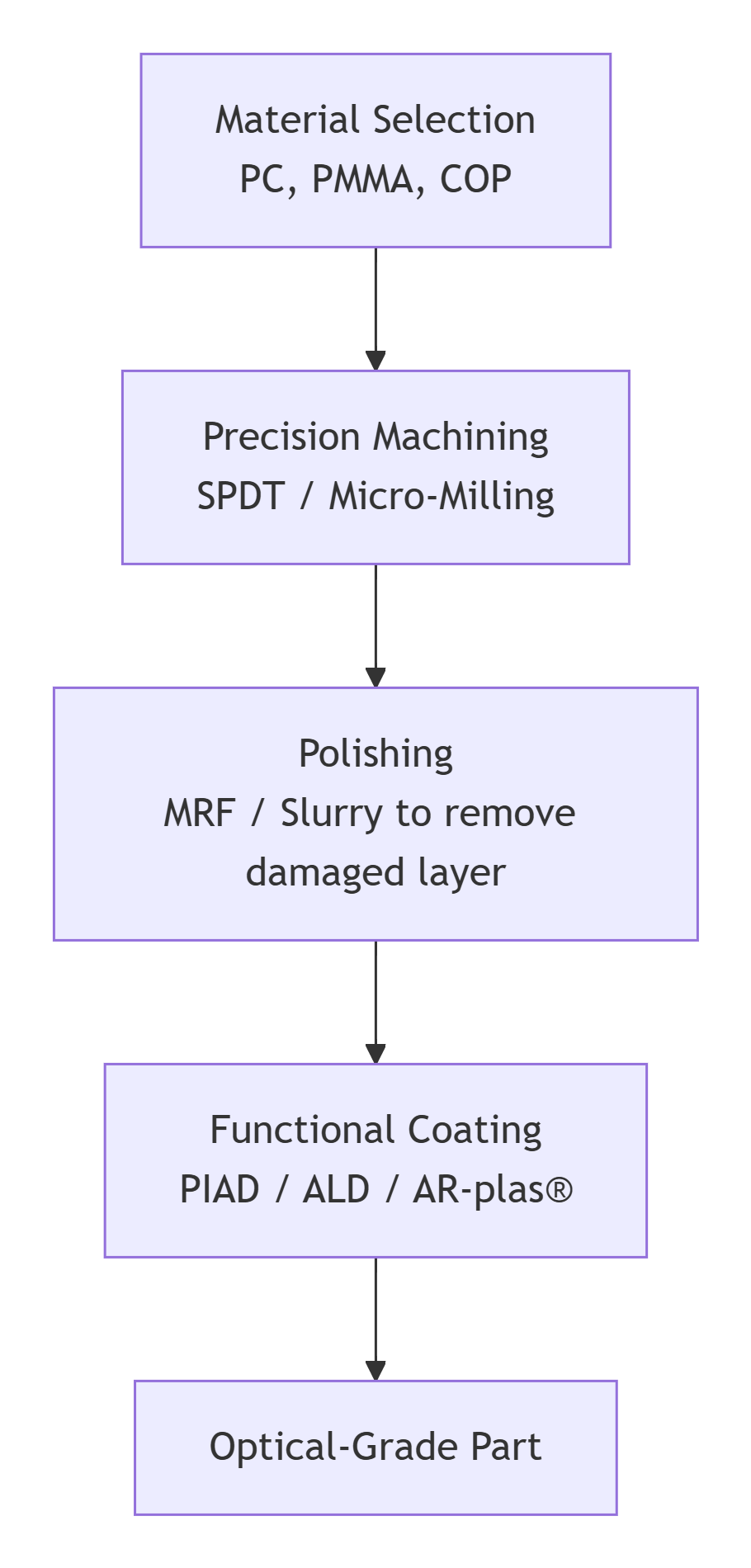
The Complete Process Chain
This is the full sequence. You cannot skip a step.
Practical Roadmap: How to Plan Your Project
Let’s just map it out. Making optical plastic parts is hard. But it’s a systematic challenge. You can get the hang of it by following a clear step-by-step process. Here’s your handy guide.
Your Project Roadmap: A Step-by-Step Plan
Don’t go straight to the machine. Just plan backwards from the final requirement.
Step 1: Define Your Specifications First. Be ruthless.
This is not the last step. It’s the first one. Make sure you write down the exact numbers. They’ll end up dictating every choice you make later on.
- Surface Roughness: Just make sure you specify it in Ra (average roughness) or RMS. Just to confirm, is 5 nm Ra acceptable, or do you need to go down to 2 nm? This will help you decide on the best polishing method.
- Optical Performance: So, can you define the transmitted wavefront error? How much can the light distort? Also, set a limit for haze.
- Coating Performance: Set a challenging target. I just wanted to check – for an anti-reflection coating, is reflectivity of less than 0.5% per surface required? Or even lower?
- Environmental Needs: Will it be exposed to high heat, humidity, or UV light? Let’s define this now.
Step 2: Select Your Material. Use the specs as your filter.
Your numbers from Step 1 narrow the choice. Don’t just go for a plastic, you know.
- Optical Needs: Just check the refractive index and Abbe number, please. Do they match your design?
- Mechanical & Environmental Needs: Is it for a rugged device? You might need polycarbonate (PC). If you’re after something that doesn’t soak up moisture, a cyclo-olefin polymer (COP) might be worth a look. If you’re looking for something that can handle chemicals, PMMA is a great option.
- Machinability: Just remember that some materials polish more easily than others. This affects cost and lead time.
Step 3: Choose your fabrication path. Volume is everything.
This is a really important moment in the company’s history.
- Path A: Prototypes or low-volume production (direct machining). You’ll machine and polish each part separately. Use SPDT for smooth surfaces and micro-milling for complex features. It’s pretty flexible, but it does cost a lot per part. It’s perfect for R&D, prototypes, or custom medical devices.
- Path B: Option B is all about making lots and lots of copies. You invest in a perfect master mold (machined with SPDT/micro-milling). Then you use injection molding to make millions of copies. The per-part cost is tiny. This is for consumer electronics and automotive sensors. Your upfront cost and time are in the mold.
Step 4: Integrate Post-Processing From the Start. Not as an afterthought.
This is where projects fail. When you’re putting together your design, timeline, and budget, make sure you include polishing and coating as part of that.
- Design for it: Do you think MRF could polish the shape of your part? I was just wondering if it has deep grooves that are tricky to coat with ALD?
- Budget for it: Post-processing can cost as much as the machining itself. Don’t underestimate this cost.
- Timeline for it: Polishing and coating take up a lot of time. A ‘quick’ diamond turn won’t get you a finished optic.
The Core Philosophy: It’s a Process Chain
This is not a checklist. It is a chain. Every link depends on the one before it.
The material you choose affects how the machining process is carried out. The machining method determines the type of damaged layer. That damage is what we need to look at when choosing the right polishing technique. The final polished surface will determine which coating technology will stick properly.
If you break one link, the chain fails. The part might look right, but it’ll have haze, scatter light, or the coating will peel.
But if you follow the chain – if you define the specs, choose the material, pick the right fabrication path for your volume and design for post-processing from day one – you can do it. You can turn a blank piece of see-through plastic into a reliable, high-performance optical component.
The challenge is real. The path is clear. Master the chain, and you master the process.

The NOBLE Advantage in Optical-Grade Machining
The process chain we just walked through is difficult. Every step has a pitfall. If you do it in-house, you’ll need to invest in machines, process knowledge and time. There is another path.
Consider the NOBLE advantage.
We are a specialized partner focused on one thing: navigating the intricate challenge of machining optical-grade optical plastic. We’ll take care of everything for you, from your first prototype to a full low-volume production run. The complexity is real. But with a team that knows what they’re doing, getting great optical quality becomes a reliable and efficient process. It stops being a research project and becomes a standard manufacturing step.
Our Team of Professional Engineers
This is the core. Your project is not handed off to a machine operator. It is overseen by a dedicated team. Our optical engineers and manufacturing engineers work together.
They’ll give you expert guidance right from the start. First, we do a design-for-manufacturability (DFM) analysis. They’ll take a look at your model and your specs. They will tell you if a radius is too sharp to polish. They’ll probably suggest a material change to reduce stress birefringence. This guidance is there for you every step of the way, from picking the machining path, planning the polishing cycle, to specifying the coating. We’ve got you covered for any technical challenges. Every problem is met by someone who has solved it before.
Fast Turnaround Times
Speed matters. Our workflow is not a standard machine shop schedule. It is optimized for optical parts. We have dedicated resources for this precise work.
The result is industry-leading lead times for high-precision components. We accelerate your development cycle. You get functional prototypes faster. You can get going on pilot production straight away. You can’t achieve this speed by cutting corners on quality. It comes from an established, streamlined process.
Efficient and Proactive Communication
You will know what is happening. We commit to clear, consistent, and technical communication. You will not get vague updates.
We inform clients at every critical milestone. The first article is cut. The MRF polishing cycle is complete. The coating chamber run is finished. More importantly, we collaborate proactively. If our engineers spot a potential issue with a tolerance during the inspection, they’ll get in touch straight away with the relevant data and a proposed solution. This ensures the final part in your hand meets all specifications. There are no surprises.
The Foundation: Quality Certifications
Processes are only as good as the system that controls them. Our commitment is formalized.
We are ISO 9001 and ISO 13485 certified. This isn’t just a plaque on the wall; it’s a proper celebration.
- Our Quality Management System is certified byISO 9001. Every procedure is documented. Every measurement is traceable. Our machines are calibrated. Our processes are controlled and repeatable.
- Just to let you know, ISO 13485 is all about medical devices. This framework is way more thorough. It’s all about managing risk, keeping documents in order, and making sure everything’s clean. It makes sure that components for surgical tools or diagnostic devices are made to the highest standards.
This will give clients in the medical, aerospace,e and automotive industries real confidence. Your optical components are not made in an ad-hoc way. They are manufactured under a certified, audited quality management system. This is the final step in our optical plastic process chain that we can’t compromise on.
The path to optical plastics is a bit of a journey. You can go it alone or get a guide who knows every turn. Let’s talk about your requirements.
FAQ
I have a design for a plastic lens. What’s the very first step I should take?
The very first step is a Design for Manufacturability (DFM) review. Do this before anything else. A perfect optical design can be impossible to make. Tolerances might be too tight. A draft angle might be missing. The material might be wrong for machining.
What is the biggest misconception about machining optical plastics?
The biggest mistake is thinking the machine finishes the job. It doesn’t. The part never comes straight off the tool with a finished optical surface. Post-processing is not an extra. It is mandatory. Optical plastic needs special polishing and a functional coating. All of this is done on top-of-the-line equipment. They’re part of the process. If you skip them, you’ll get a prototype, not a component.
My project has a very tight timeline. How can you get things done quickly without compromising on quality?
Speed and quality come from the same place: a controlled system. They’re not a trade-off. Our fast timelines are down to three things:
- Proactive DFM. We nip problems in the bud in the design phase before they turn into delays on the shop floor.
- Dedicated Management. You’ve got a clear point of contact. Communication is efficient. Nothing gets lost.
- In-House Process Chain. We do everything here. Precision machining (SPDT), advanced polishing (MRF), functional coating (PIAD). We don’t outsource steps. This means you won’t have to wait for other vendors, and you’ll always get the same consistent service. We’ve got control over every stage of the process, so you can be sure the quality is always going to be there.
Why can’t I just use a standard machine shop for my clear optical plastic parts?
Standard shops lack the necessary environment. They don’t have vibration-damped floors or clean air. They don’t have the same high-end tooling, like single-crystal diamond cutters. They don’t really know much about the critical post-processing steps, like magnetorheological finishing or thin-film coating.
If you try this in a standard shop, it’ll most likely end up as scrap. The parts will have haze. They will be scratched. The dimensions will be wrong. You pay for an optical plastic part that doesn’t even do the job it’s supposed to.
How do you handle communication and updates throughout an optical plastic project?
We take care of it ourselves. Good work needs clear communication. From the outset, you’ll be assigned a dedicated project engineer. This person is your main point of contact.
We’ll keep you in the loop at every stage: when the material’s ordered, after the first article’s been cut, during polishing, after coating, and at final inspection. These updates often include detailed inspection reports with data.