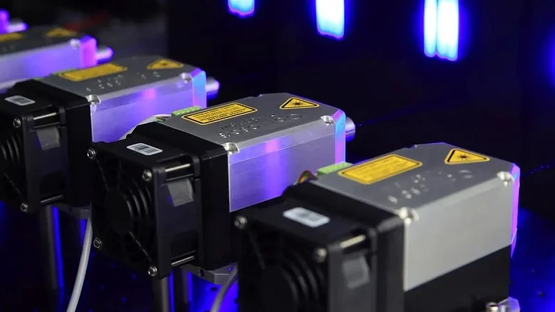
Picture a large data center working with millions of requests each second. Inside each switch, a small optical module housing works quietly. This carefully made enclosure protects fragile parts, removes heat, and stops electromagnetic interference.
Without proper housing, optical transceiver modules fail. Overheating kills lasers. EMI corrupts signals. Mechanical stress breaks connections. These failures damage fiber optic communication systems.
The right housing allows high-performance connectivity. Engineers pick from metals, ceramics, and alloys. They choose making methods like die casting or machining. They match housings to form factors from SFP to QSFP-DD.
By the end, you will know how to compare housing choices for performance, reliability, and cost.
Why Optical Module Housings Matter
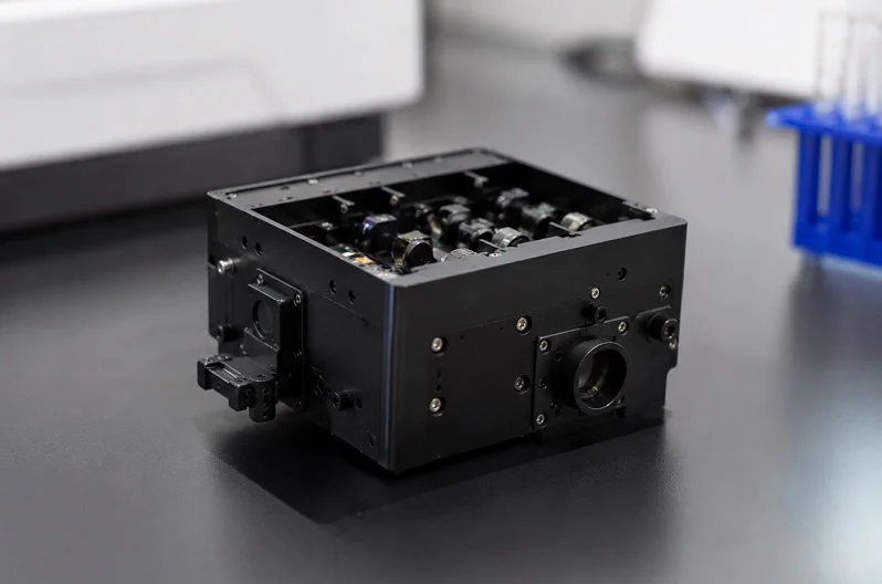
Protecting Performance and Reliability
Think of the optical module housing as the first line of defense. It shields sensitive optical parts from physical harm. Dust, moisture, and mechanical stress can damage fragile lasers and photodetectors. Without a strong enclosure, these parts fail quickly. The housing also helps manage heat. Lasers and digital signal processors (DSPs) produce a lot of heat. In crowded data centers, that heat builds up fast. If the housing can’t move heat away, performance drops. The module might even turn off. A good housing design keeps temperatures steady. It uses materials like aluminum to pull heat away from hot spots. This directly affects reliability. Cooler parts last longer. They also work more consistently. So the housing isn’t just a box. It’s a key part of the thermal path.
Enabling High-Speed Data Transmission
High-speed data transmission needs more than fast electronics. It needs clean signals. Electromagnetic interference (EMI) is a big issue. Without proper shielding, EMI corrupts data. It causes crosstalk between nearby modules. That ruins signal quality. The optical module housing works like a Faraday cage. It keeps electromagnetic radiation inside the module. It also blocks outside interference from reaching the parts. This is vital for high-speed optical modules. At 400G and 800G speeds, even tiny interference causes errors. The housing must be conductive. Zinc and aluminum alloys work well for this. They create a continuous shield around the electronics. The design also needs precise fitting with cage connectors. Any gap in the housing lets EMI escape. So manufacturing tolerances matter. A well-made housing keeps signals clean and fast. It enables the data speeds that modern networks need.
Core Functions of Optical Module Housings
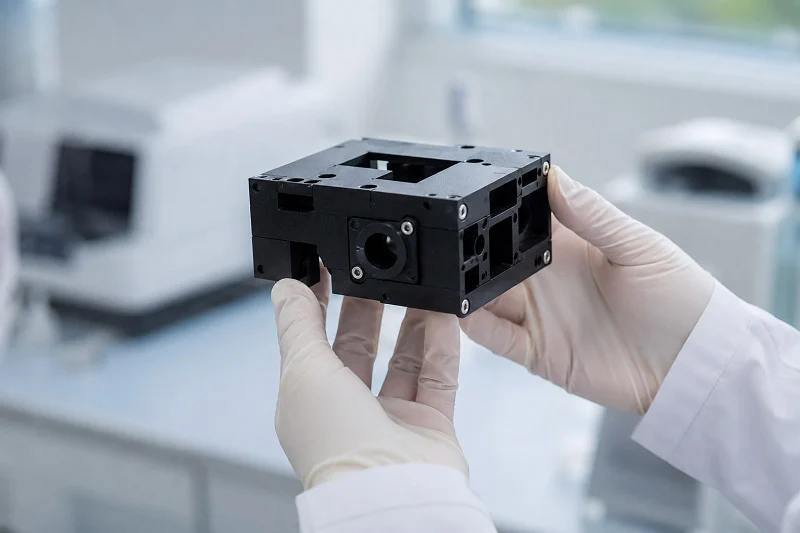
Mechanical Interface and Alignment
The optical module housing must fit perfectly with the cage connector on the host board. Think of it like a key sliding into a lock. The housing’s outer dimensions follow strict standards, so it mates correctly every time. When you push a module into a switch port, the housing guides the electrical connector into place. A misaligned housing causes bent pins or poor electrical contact. That leads to intermittent failures that are hard to diagnose.
Heat sinks also depend on precise alignment. The housing top surface presses against a heat sink or thermal pad. If the housing has even a small warp, the gap reduces heat transfer. The module runs hotter than designed. This shortens component life and can trigger thermal shutdowns. Manufacturers hold tight tolerances on the mating surfaces. They also control the latching mechanism’s position. The latch must engage securely but release smoothly. Too loose, and vibration disconnects the module. Too tight, and technicians struggle during maintenance.
EMI Shielding and Signal Integrity
Electromagnetic interference poses a constant threat to high-speed signals. The housing acts as a Faraday cage, containing radiation from the module’s electronics. It also blocks external interference from reaching sensitive components. Conductive materials like zinc or aluminum alloys create this shield. The entire enclosure must maintain electrical continuity. Every seam, screw hole, and vent becomes a potential leak point.
Designers pay close attention to these gaps. They space screws properly to keep the shield continuous. They add spring fingers or conductive gaskets at the connector opening. These features maintain contact between the housing and the cage. Without them, EMI escapes and corrupts neighboring modules. Cross-talk between adjacent ports increases bit error rates. At 400G speeds, even tiny leaks cause retransmissions that slow the network.
The housing must balance multiple jobs at once. It provides mechanical strength for repeated plugging cycles. It creates a solid thermal path for heat removal. And it contains electromagnetic energy. These functions sometimes compete. A thicker wall improves shielding but adds weight. More vent holes help airflow but create EMI leaks. Good design finds the sweet spot. That balance directly supports thermal management while keeping signals clean. Engineers evaluate each trade-off carefully during the design phase.
Materials for Optical Module Housings
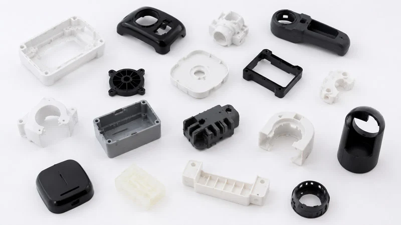
Picking the right material for an optical module housing means balancing heat, weight, cost, and shielding. Each metal has its own strengths. The choice affects how well the module works and how much it costs to make. Engineers don’t choose a material for just one reason. They look at everything together.
Metals: Aluminum, Zinc, and Copper Alloys
Aluminum is the most common choice for optical module housings. It is light, which is important in crowded data centers where every gram matters. It moves heat away from lasers and DSPs very well. Aluminum also costs less than other high-performance metals. For most uses, it gives a good balance of performance and price. You will find aluminum in many module types, from SFP to QSFP-DD.
Zinc has different advantages. When melted, zinc flows very easily. That lets makers cast complex shapes with thin walls and fine details. Zinc housings are strong and hard, so they last through many plugging cycles without wearing out. They also often cost less than aluminum. But zinc has a problem: it rusts easily. Surface treatments like plating or coating are needed to protect the housing over time. Even with that extra step, zinc is still a common choice for modules that need detailed shapes.
Copper alloys give the best heat performance of the three. Heat moves through copper faster than through aluminum or zinc. For high-power modules that get very hot, copper helps a lot. The downside is that copper costs more. It is also harder to cast with fine details, so makers have more trouble with complex shapes. You usually see copper in special modules where heat is the biggest problem.
| Material | Key Strengths | Trade-offs |
| Aluminum | Light, excellent heat transfer | Harder to die-cast with fine details |
| Zinc | Great EMI shielding, flows easily for complex shapes, strong, low cost | Rusts easily, needs surface treatment |
| Copper | Best heat transfer | Expensive, hard to die-cast with fine details |
Ceramics and Engineering Plastics
Metals are most common, but ceramics and plastics have important uses. Ceramics can handle very high and low temperatures without falling apart. They also block electricity, which metals cannot. These features make ceramics good for special applications where heat and electrical isolation are both needed. The downside is cost and fragility. Ceramic housings cost more to make and can crack under stress. So they are used mainly in special or high-reliability situations.
Engineering plastics like LCP (liquid crystal polymer) and PPS (polyphenylene sulfide) are light and cheap. They can handle medium heat well enough for lower-speed modules. They also let makers create complex molded shapes in large amounts. Injection molding with plastics costs less than die-casting metal, especially for big batches. But plastics cannot match metals for heat transfer or EMI shielding. For 10G or 25G modules, that trade-off often works. For 400G and faster, plastics usually don’t work.
The final choice of material depends on what the customer needs. Heat budget sets the minimum: how much heat must the housing move? Weight limits matter for portable or space-limited gear. Cost goals shape every decision. Environmental conditions add another layer. Will the module face humidity, vibration, or temperature changes? Each factor moves the choice in a different direction. Engineers think about all of them together before picking a material. Getting this right early saves time and money later in production.
Manufacturing Processes for Optical Module Housings

Making a housing means picking the right process for the volume and material. Each method has its own strengths. The choice affects cost, quality, and how fast you can get parts. The three main processes are die casting, CNC machining, and injection molding. Each one serves a different need.
Die Casting: The Industry Standard
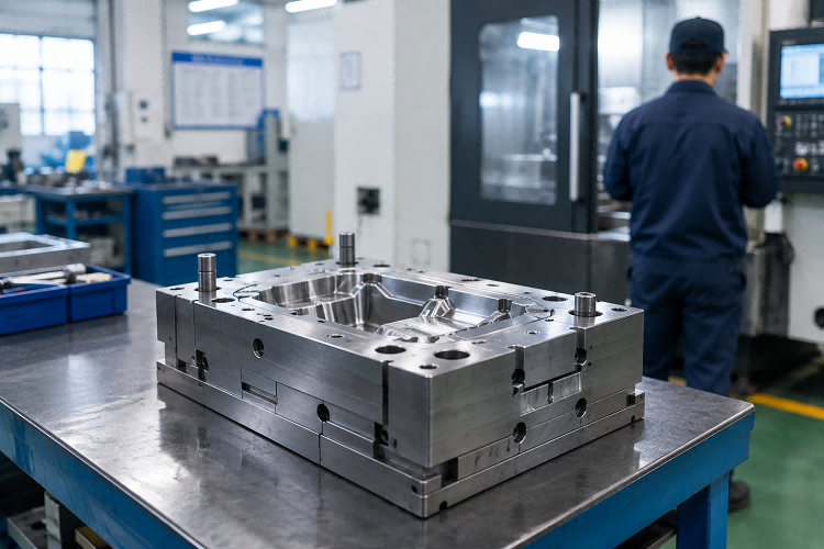
Die casting is the most common way to make metal housings. The process pushes molten metal into a steel mold under high pressure. Aluminum and zinc alloys work best here. The metal cools fast, forming a part with tight dimensions and a smooth surface. The pressure ensures the metal fills every corner of the mold. This creates consistent results across thousands of parts.
Dimensional accuracy matters a lot for these parts. The housing must fit perfectly with cage connectors and heat sinks. Die casting holds tolerances well. Parts come out consistent from the first shot to the ten-thousandth. That repeatability is hard to beat. Even small variations in the housing can cause alignment problems. So the process must stay stable throughout the run.
Surface finish is another benefit. Die-cast parts have a smooth outer surface. This helps heat move from the housing to the heat sink. A rough surface creates tiny air gaps. Those gaps trap heat and reduce performance. The smooth finish also helps with EMI shielding. Fewer gaps mean less radiation can escape. The surface quality comes from the polished steel mold. That mold transfers its smooth finish to every part.
Cost depends on volume. The mold costs thousands of dollars upfront. That’s the barrier. But once the mold is ready, each part costs very little. For a small part like an optical module housing, the break-even point sits around 400 to 800 pieces. Above that volume, die casting beats machining on cost every time. At 10,000 parts or more, the per-part cost drops dramatically. The tooling investment pays off over the long run.
| Criteria | CNC Machining | Die Casting |
| Tooling Cost (Initial) | None to Low | High |
| Per-Part Cost (High Volume) | High | Low |
| Ideal Volume Range | 0–500 parts | 10,000+ parts |
| Break-Even Volume | 1–2,000 parts | ~5,000–10,000 parts |
The table shows the general picture for larger parts. For small housings, the break-even point is lower. The key takeaway is simple: high volume drives the choice toward die casting. The mold cost spreads across more parts, making each one cheaper.
Precision Machining and Injection Molding
CNC machining takes a different approach. A computer-controlled tool cuts the housing from a solid block of metal. There is no mold to make. No tooling cost upfront. This makes CNC ideal for small runs and prototypes. You can make a single part or a dozen without a big investment.
Volume drives the decision here too. For annual volumes below 1,000 units, CNC machining is usually cheaper. You pay more per part, but you avoid the mold cost. The flexibility is also a big plus. Design changes are easy. You just update the program and run a new part. Engineers can test different designs and alloys without waiting for a new mold. This speeds up development cycles. It also reduces risk when trying new approaches.
For plastic housings, injection molding is the preferred process. The plastic melts and gets forced into a mold under pressure. The process can create complex shapes with thin walls. Micro injection molding can achieve wall thicknesses as low as 0.1 mm. That depends on the material flow and the part design. LCP and PPS flow well into detailed molds. They create housings that are light, strong, and handle moderate heat. The thin walls save material and reduce weight. That matters in dense data center environments.
Choosing the right combination of materials and manufacturing processes directly affects the final cost and performance. Engineers weigh these factors against the project’s volume and budget. Low volume points to CNC. High volume for metal points to die casting. High volume for plastic points to injection molding. Each process has a clear sweet spot. Getting the choice right saves time and money.
Precision in Optical Module Housing Manufacturing
Making these parts requires very tight control of every measurement. The housing must fit perfectly into the switch port. Even a small mistake can cause big problems in the network.
Dimensional Tolerances and Surface Finish
An optical module housing needs very tight tolerances. That is about half the width of a human hair. Why is this so important? The housing must line up exactly with the cage connector. Even a tiny misalignment can bend pins or cause bad electrical contact. The heat sink also needs a perfect fit. If the housing top surface is too high or too low, the gap for heat transfer gets bigger. Heat builds up inside the module. The lasers and DSPs run hotter than they should. Performance drops.
Surface finish also matters a lot. A rough surface makes tiny air gaps between the housing and the heat sink. Air traps heat and slows down heat transfer. The rougher the surface, the worse the heat flow. EMI shielding also gets worse. Gaps in the surface let electromagnetic radiation escape. That causes cross-talk between nearby modules. Manufacturers aim for a smooth finish. They polish the mold surfaces and control the casting process carefully. This keeps the housing surface the same every time.
Quality Control and Inspection Methods
Checking every housing for defects is very important. Coordinate measuring machines (CMMs) are the main tool. A CMM probes the housing at many points. It compares each measurement to the CAD model. If any point is outside the tolerance, the housing fails. CMM inspection finds measurement errors before they cause problems in the real world.
Surface profilometry measures the roughness. A tiny stylus drags across the surface. It records the high points and low points. The results tell engineers if the surface is smooth enough for good heat contact. For sealed housings, leak testing is critical. The housing gets filled with air under pressure. A sensor checks for any pressure drop. Even a tiny leak lets in moisture or dust. That can damage the optical parts over time.
These quality control methods make sure every housing meets the needed standards. The mix of tight tolerances, smooth surfaces, and careful inspection creates reliable parts. The manufacturing processes must stay the same to get these results in large numbers.
Optical Module Housing Types by Form Factor
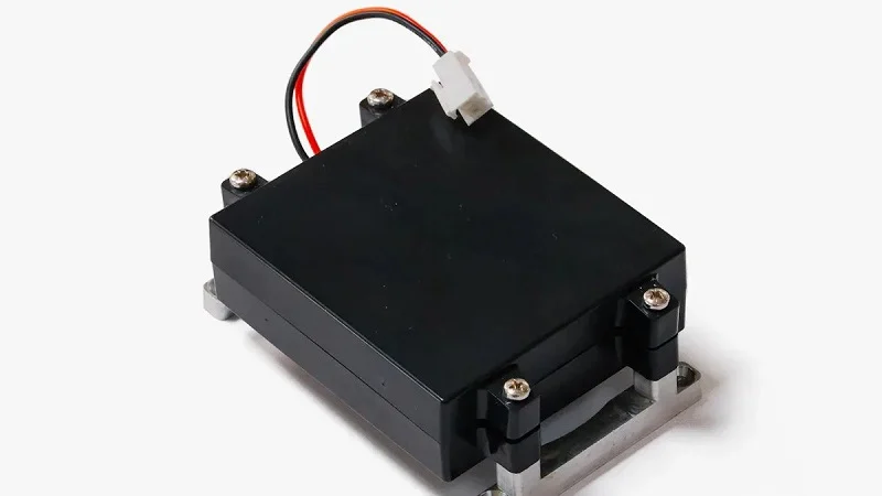
Form factors tell you the shape and size of optical modules. Each one follows a Multi-Source Agreement (MSA) that sets standard sizes. This makes sure modules from different companies fit into the same switch ports. The housing design changes with each form factor to handle different power and heat needs.
Small Form Factors: SFP, SFP+, and SFP28
The SFP family covers speeds from 1G to 25G. These small, hot-pluggable housings slide into cages on switches and routers. They work well for short-range links inside data centers and for longer connections between buildings.
SFP housings are small and light. Most use zinc or aluminum die-cast bodies. Zinc flows well into thin walls, so makers can create detailed latch mechanisms. Aluminum offers better heat transfer for SFP+ and SFP28 modules that run warmer. The housing must keep the electrical connector lined up with the cage. Even a small shift causes signal problems.
These modules plug and unplug often. Technicians swap them during maintenance or upgrades. The housing needs a sturdy latch that lasts through hundreds of cycles. The guide rails on the sides must stay smooth. Any burr or rough edge makes insertion hard. Surface finish matters here for both function and feel.
High-Density Form Factors: QSFP, QSFP-DD, and OSFP
The QSFP family handles much higher speeds. QSFP supports 40G to 100G. QSFP-DD doubles the density with extra rows of contacts, reaching 400G. OSFP also targets 400G and 800G use cases. These larger housings have bigger footprints and more complex internal layouts.
Heat becomes the biggest challenge at these speeds. More data means more power. The housing must move that heat away well. QSFP-DD modules typically draw 12–15W. OSFP modules for 800G need 20–25W or more. That extra power creates more heat inside the same general space.
800G modules use more power than 400G modules, and they should only be used in 400G platforms that can provide enough power and remove heat for 800G modules.
| Form Factor | Typical Power Range |
| QSFP-DD | 12–15W |
| OSFP | 20–25W+ |
The optical module housing for these high-power parts uses thicker walls and larger surface areas. Some designs add fins on the top surface to increase airflow contact. Others use copper inserts at hot spots. The MSA sets the outer dimensions, but makers have freedom inside those limits. They choose the best material and internal shape for better thermal paths and EMI control. This flexibility lets each company tune the housing for specific performance goals.
Thermal Management in Optical Module Housings
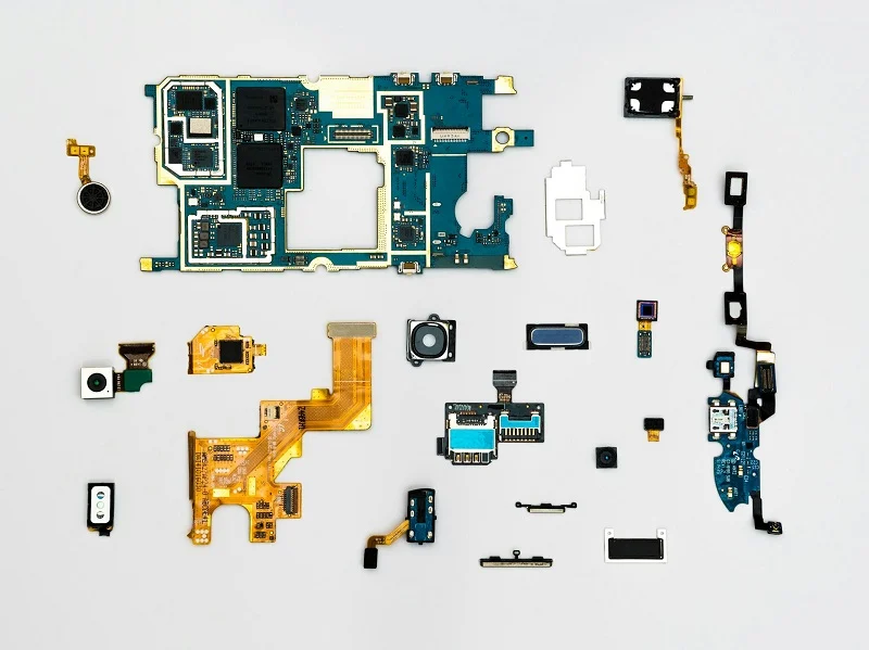
Heat is the biggest problem for modern optical modules. Lasers, photodetectors, and DSPs inside the housing all make heat. In a crowded data center, that heat builds up fast. Without good thermal management, temperatures rise quickly. Performance drops, and parts can fail. The housing must pull heat away from these hot spots.
Heat Dissipation Strategies
The choice of materials directly affects heat transfer. Aluminum is the most common option. It conducts heat well and keeps weight low. For hotter modules, copper alloys work better. Heat moves through copper about twice as fast as through aluminum. The trade-off is higher cost. Engineers pick the right materials based on the module’s power budget.
Housing design matters just as much as material choice. Some housings add fins on the top surface. These fins increase the area that contacts moving air. More surface area means more heat escapes. Heat spreaders inside the housing help too. They pull heat from the hottest spots and spread it across a larger area. This keeps temperatures more even.
The housing also needs a good thermal path to the system heat sink. The top surface must press against a thermal pad or heat sink. Any gap traps heat. That’s why the surface must be smooth. Keeping the housing height exactly right also helps.
Thermal Interface Materials and Innovations
Thermal interface materials (TIMs) fill the tiny gaps between the housing and the heat sink. Without them, air pockets block heat flow. Thermal pads are the most common choice. They are soft and mold to surface roughness. Phase-change materials work differently. They start as solid pads. When they heat up, they melt and flow into every gap. This gives better contact than standard pads.
For high-power modules, standard approaches may not be enough. Vapor chambers and heat pipes offer a solution. A vapor chamber is a flat, sealed container with a small amount of liquid inside. Heat turns the liquid to vapor. The vapor moves to cooler areas and turns back to liquid. This cycle moves heat much faster than solid metal alone.
These new ideas make thermal stability possible even at 800G speeds. The housing becomes an active part of the cooling system. It does not just hold parts. It moves heat away well. Good thermal management is critical as data rates keep climbing. Future modules will need even better thermal performance.
Optical Module Housing Design Considerations
Cost vs. Performance Trade-offs
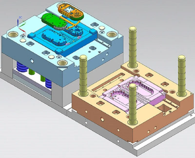
Money drives many housing choices. The way you make the housing changes the final price. Die casting needs a steel mold that costs thousands of dollars upfront. That sounds like a lot. But once the mold is ready, each part costs very little. The numbers work out when you need many housings. At high volumes, the mold cost spreads across thousands of parts. Each one becomes cheap.
CNC machining works differently. No mold means no upfront tooling cost. You can order just a few parts without wasting money. But each machined part costs more. The machine takes time to cut each housing from a solid block. That labor adds up. For small runs, machining wins. For big production, die casting takes over.
The materials you pick also change the balance. Aluminum gives good heat transfer at a fair price. Copper works better but costs more. Zinc allows complex shapes at low cost but needs extra surface treatment. Every choice trades something for something else. Engineers weigh these trade-offs against the project’s budget and performance goals.
Environmental Durability and Reliability
Every optical module housing faces tough conditions. Data centers run hot. Outdoor equipment deals with freezing nights and humid days. Vibration shakes modules constantly. The housing must survive all of this without cracking or warping.
Temperature cycling is one of the hardest tests. Telcordia GR-468-CORE sets the standard for optical components. The test pushes housings through repeated temperature swings. Parts go from -40°C to 70°C or 85°C. They repeat this cycle up to 1,000 times. This mimics years of real-world use in a short period.
| Test ID | Requirement |
| 5.20 | Temperature cycling: -40 to 70°C (or 85°C) per MIL-STD 883, method 1010, 100 to 1,000 cycles |
Reliability testing goes beyond temperature. Thermal shock tests hit parts with sudden temperature changes. Accelerated life testing runs modules at high stress to find weak points. Mechanical stress tests check how housings handle vibration and physical impact. These tests catch design flaws before products ship to customers.
A housing that passes these tests earns trust. It keeps working when the network depends on it. That reliability matters more than saving a few cents per part.
Standards for Optical Module Housings

MSA, IEEE, and Industry Specifications
Multi-Source Agreements (MSA) set the rules for how optical modules look and fit. These agreements define the exact mechanical dimensions for each form factor. They also specify connector interfaces and thermal requirements. When a company designs a new module, they follow the MSA for their target form factor. This ensures their product works with any switch or router that follows the same standard. Without MSA compliance, a module simply won’t fit into the cage. The housing must match these dimensions precisely. Even small deviations cause alignment problems with the electrical connector.
IEEE standards handle the electrical and optical side of things. These standards define signal speeds, power levels, and performance parameters. The housing design must support these requirements. For example, a housing for a 400G module needs enough shielding to keep signals clean at those speeds. The IEEE standards don’t tell you how to build the housing. They tell you what performance the final module must achieve. Engineers work backward from those requirements to design the enclosure.
Environmental and Safety Certifications
Environmental regulations control what materials can go into an optical module housing. RoHS restricts hazardous substances like lead, mercury, and cadmium. But there are exemptions. For instance, lead in aluminum alloys is allowed up to 0.4% by weight under exemption 6(b). This matters because many housings use aluminum die casting. The exemption recognizes that removing all lead from aluminum alloys isn’t technically practical yet. REACH is another regulation. It covers a broader range of chemicals and requires manufacturers to register their use.
Safety certifications protect users and equipment. UL certification tests housings for fire resistance and electrical safety. A UL-listed housing has passed rigorous testing. This certification matters for data center equipment that runs 24/7. ISO 9001 focuses on manufacturing quality. It ensures the factory has proper quality management systems in place. When you buy from an ISO 9001-certified manufacturer, you know they follow consistent processes. These certifications work together. They protect the environment, keep users safe, and ensure every optical module housing meets the same quality bar.
Future Trends in Optical Module Housings
Advanced Materials and Manufacturing Technologies
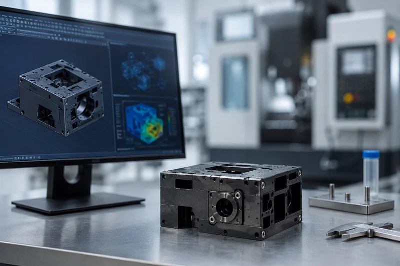
The next generation of housings will use new materials and fresh ways to make parts. Advanced composites mix strength with light weight. They handle heat well and don’t weigh much. That helps in dense switches where every gram counts. Additive manufacturing, or 3D printing, opens another door. It builds parts layer by layer. This method creates complex internal channels that traditional casting cannot make. Those channels can route coolant or house heat pipes. Prototyping gets faster too. Engineers print a new design overnight instead of waiting weeks for a mold. That speed cuts development time and lets teams test more ideas.
These new methods don’t replace die casting for big production runs. But they change how designers think. They can try bold shapes without huge tooling costs. The best designs then move to traditional processes for volume. This mix of old and new keeps costs down while pushing performance up. The choice of materials still drives the final result. Better materials mean better heat flow and cleaner signals.
Co-Packaged Optics and Evolving Form Factors
Co-packaged optics (CPO) marks a big shift. Instead of pluggable modules, optical engines sit right next to the switch chip. This cuts distance and saves power. The market is still young. Fortune Business Insights valued the global co-packaged optics market at USD 256.2 million in 2025. That number will grow fast as data centers chase efficiency.
CPO changes the housing game completely. The optical module housing for CPO must handle heat in a much tighter space. The table below shows the difference.
| Aspect | Co-Packaged Optics (CPO) | Pluggable Modules |
| Spatial constraint | Heat dissipation within a more constrained space, requiring sophisticated cooling solutions that consume additional power | Independent thermal management strategies possible, but may operate in less optimal thermal environments depending on host system design |
| Thermal coupling | Proximity to high-power switching ASICs creates localized hot spots exceeding 85°C, degrading laser performance; thermal crosstalk between co-located components is a key issue | Faces challenges maintaining consistent temperatures across varying ambient conditions and airflow patterns |
| Cooling approach | Requires innovative thermal interface materials and micro-channel cooling; often liquid-cooled | Standard form factors (QSFP-DD, OSFP) impose strict power budgets (12-15W), forcing advanced heat sinks and thermal pads |
One clever fix keeps the laser outside the package.
The ELS generates continuous-wave light at one or more wavelengths and distributes it to multiple optical engines via optical splitters or wavelength multiplexers. Keeping the laser external reduces heat on the ASIC package and improves overall system reliability.
This approach spreads heat sources apart. It also simplifies the housing design. As data rates climb toward 1.6T, these trends will push every part of the housing to work harder. Tighter tolerances and smarter materials will separate the winners from the rest.
NOBLE: Precision Optical Module Housing Manufacturing

Our Manufacturing Capabilities and Certifications
NOBLE is a top Chinese maker of precision housing parts for optical modules. We have three main ways to make parts: die casting, CNC machining, and injection molding. Each method serves a different purpose. Die casting is good for making many metal parts. It gives the same results across thousands of pieces. CNC machining works better for small runs or prototypes. You get fast turnaround without needing a mold. Injection molding makes plastic housings. It creates complex shapes with thin walls at a low cost per part.
Quality is important at every step. Our factory is certified for quality management. We also have certifications for specialized quality standards. The same careful approach applies to every optical module housing we make. We measure dimensions with coordinate measuring machines. We test surface finish with profilometers. We check sealed housings for leaks. Every part meets the same high standard.
From Design to Assembly: Complete Solutions
We give great service from the very first design idea. We help customers with both fast prototyping and mass production. Our team looks at your housing design and suggests changes that make it easier to build. Small changes save time and money later. Maybe a wall thickness change helps the metal flow better in the mold. Maybe a different alloy choice improves heat transfer without raising cost. We find these things early.
The process continues through assembly. We handle the final steps that turn a housing into a finished module. This means you have fewer suppliers to manage. It also means better communication between design and production. One team handles everything from start to finish. That cuts down on mistakes and delays.
We also help with materials selection. The choice affects how a housing performs. Aluminum gives good heat transfer at a fair price. Zinc flows well for complex shapes. Copper handles the hottest modules. We help you pick the right one for your needs. Our engineers know how each material behaves in the mold and in the final product. That knowledge saves our customers time and money on every project.
The optical module housing does more than protect parts. It enables the data speeds modern networks demand. Every choice matters. The materials you select change heat flow, shielding, and cost. The manufacturing process affects precision and price per unit. Understanding form factors helps you match the right housing to your application. Thermal management keeps lasers and DSPs cool enough to perform. As data rates climb toward 1.6T, housing innovation becomes central to progress. New materials and cooling methods will separate winners from the rest. Don’t leave these decisions to chance. Talk to manufacturing experts like NOBLE. They can help you optimize your optical module housing for performance, reliability, and manufacturability.
FAQ on Optical Module Housing
What material keeps an optical module housing coolest?
Aluminum is the standard choice for an optical module housing. It pulls heat away from hot components without adding much weight. Copper works better for high-power modules but costs more. Zinc needs extra plating to prevent rust. Pick based on your heat budget.
When should I choose die casting instead of CNC machining?
Die casting makes sense for high volumes, say 10,000 units or more. The metal mold costs thousands upfront, but each housing becomes very cheap. CNC machining has no tooling cost. Each part costs more, so it fits small runs under 500 pieces.
How does a QSFP-DD housing differ from a basic SFP housing?
QSFP-DD optical module housings are larger and handle more power, around 12 to 15 watts. They need thicker walls and better heat paths. The outer dimensions still follow the MSA standard. The internal design changes to manage the extra heat.
Can plastic housings work for high-speed optical modules?
Plastic works for lower-speed modules where heat and EMI needs are lower. For higher-speed modules, plastic cannot match metal for heat transfer or shielding. Engineers pick the material based on the speed grade.